________________________________________________________________________________
Case IH Tractor Independent PTO
The power take off used on Case IH Tractor 385/485/585/685 is an
independent type. The pto is available as a single speed (540 rpm) unit
or as a dual speed (540 and 1000 rpm) unit. Oil for the pto unit on
tractor models is furnished from the hydraulic pump through the multiple
control valve.
From the MCV, the oil is supplied through a cored passage in the rear
frame to the 1000 rpm output shaft or lower pto drive shaft to actuate
the pto clutch. Operation of the pto clutch unit is controlled by a
spool type valve located in the MCV housing.
Pto control linkage adjustments
Although some checks and adjustments can be accomplished without
removing left rear wheel, most mechanics prefer to remove the wheel to
gain working room.
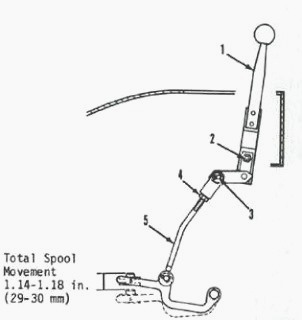
Fig.13. PTO control linkage used on Case IH Tractor
385/485/585/685 not equipped with cab
To adjust the pto linkage on tractor models without cab, refer to Figure
and move control lever (1) for-ward and rearward to check total control
spool movement. Total spool movement should be 1.14-1.18 inches (29-30
mm).
If not, remove pin (3), loosen lock-nut (4) and adjust clevis on link
(5) to obtain correct total spool movement. Install pin and tighten
lock-nut.
Make certain control lever has a small amount of clearance between lever
and end of slot in console. If necessary, loosen clamp bolt (2) and
while holding linkage in position move lever to adjust. Then, tighten
clamp bolt.
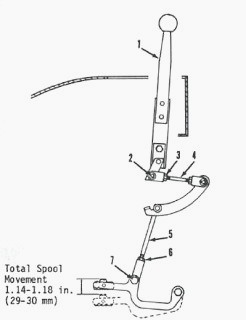
Fig.14. PTO control linkage used on models equipped with cab
To adjust the pto linkage on models equipped with cab, refer to Figure
and move control lever (1) forward and rearward to check total control
spool movement. Total spool movement should be 1.14-1.18 inches (29-30
mm).
If not, remove pin (7), loosen lock-nut (6) and adjust clevis on link
(5) to obtain correct total spool movement. Install pin and tighten
lock-nut.
Check to see that control lever has a small amount of clearance at each
end of slot in console. If necessary, remove pin (2), loosen locknut (3)
and adjust clevis on link (4) until clearance is obtained. Install pin
and tighten locknut.
Operating pressure test
To check operating pressure, operate tractor until hydraulic fluid is
warmed to at least 100° F (38° C). Connect a 0-300 psi (0-2000 kPa)
pressure gage (1) to the tee fitting (2).
Start tractor and operate at low idle speed. Move pto control lever forward to engaged position. Pressure reading on gage should be 260-270 psi (1790-1860 kPa).
If reading is correct, there is no problem in hydraulic system of the pto. If reading is not correct, remove test gage and remove pressure line from MCV to tee fitting.
Cap tee fitting and connect test gage to the pto outlet union on the
MCV. Operate engine at low idle speed and move pto control lever forward
to engaged position.
If pressure was low in first test but is now
correct, check for following conditions and correct as required:
- Damage to lock ring seals on bottom pto shaft.
- Damage to pto shaft bushing in transmission housing.
- Damage to seals or piston in pto clutch of Case IH Tractor.
- If pressure is low in second test, there is a fault in the hydraulic
supply, pto spool, regulator valve or MCV gasket.
With the 0-300 psi (0-2000 kPa) pressure gage still connected to the pto
outlet union on the MCV, move pto control lever rearward into disengaged
position. Reading on gage must be zero. A pressure reading on the gage
would indicate that spool is not fully up or there is wear on the spool
lands.
Move the control lever forward until the pto spool moves downward
0.39-0.43 inch (10-11 mm) (initial engagement position). Pressure
reading should be 41-46 psi (283-317 kPa).
Record the gage reading, then move control lever fully rearward to
disengaged position. Move control lever fully forward to engaged
position. Gage reading should be 260-270 psi (1790-1860 kPa).
If initial engagement pressure is low but the full engagement pressure
is correct, remove the pto spool assembly. See Figure. Inspect the spool
lands and if in good condition, add a shim (7). Each shim will increase
the initial engagement pressure 3 psi (21 kPa).
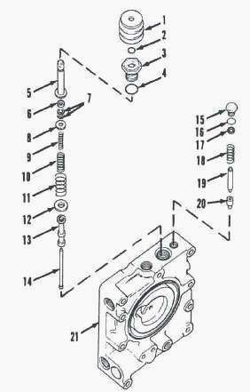
Fig.15. PTO control spool and regulator valve
If the initial engagement pressure is correct but the full engagement
pressure is low, remove regulator valve (15 through 20), Inspect the
regulator valve poppet (20) and seat and if in good condition, add a
shim (17).
Each shim will increase the full engagement pressure 20-30 psi (138-207
kPa). Repeat pressure tests after adding shims or renewing any parts.
Case IH Tractor 385/485/585/685 PTO
clutch, shafts and gears
Overhaul
To remove the pto clutch, first drain range transmission and remove
clutch cover or transfer case, as equipped. Rotate upper pto output
shaft until roll.
Drive roll pin from clutch and shaft. Unbolt and remove lower pto shaft
cover or seal housing, as equipped, and remove gasket from rear of
tractor.
Have helper support pto clutch and idler gears, if so equipped. Withdraw
1000 rpm output shaft (dual speed) or lower drive shaft (single speed).
Remove idler gears, if so equipped, and pto clutch as shaft is
withdrawn.
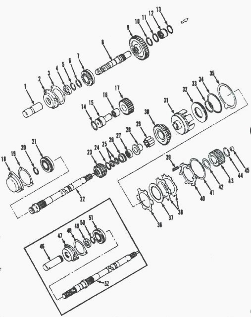
Fig.16. Pto clutch, gears and shafts. Inset shows the 1000 rpm
shaft used In place of lower drive shaft
1-Shaft cover, 2-Bearing & seal retainer, 3-Gasket, 4-Oil seal, 5-Snap
ring, 6-Washer, 7-Ball bearing, 8-540 rpm shaft, 9-Gear, 10-Snap ring,
11-Snap ring, 12-Needle bearing, 13-Snap ring, 14-"O" ring, 15-Idler
shaft, 16-Needle bearing, 17-Idler gear, 18-Cover, 19-Gasket, 20-Snap
ring, 21-Ball bearing, 22-Lower drive shaft (540 rpm), 23-Gear, 24-Snap
ring, 25-Seal rings, 26-Bushing, 27-Needle bearing, 28-Sleeve, 29-Roller
bearing, 30-Idler gear, 31-Clutch cup, 32-Piston, 30-O ring (inner),
34-"O" ring (outer), 35-Brake ring, 36-Piston back plate, 37-Friction
disc, 38-Drive plates, 39-Return springs, 40-Clutch back plate, 41-Snap
ring, 42-Thrust washer, 43-Clutch hub, 44-Snap ring, 45-Needle bearing,
46-Shaft safety cover, 47-Bearing seal retainer, 48-Gasket, 49-Oil
seal, 50-Snap ring, 51-Ball bearing, 52-1000 rpm shaft
To disassemble the pto clutch, first use a pair of "C" clamps or a
suitable puller and compress the return springs (39), then remove snap
ring (41). Remove clamps or
puller and remove clutch back plate (40) and return springs (39).
Remove friction discs (37), drive plates (38), piston back plate (36)
and brake ring (35). Remove snap ring (44), thrust washer (42) and
clutch hub (43). Bump front of
clutch cup (31) on bench top and remove piston (32) with "O" rings (33
and 34).
Case IH Tractor Standard duty pto clutch has five friction discs and
eight drive plates (two drive plates between each friction disc). Heavy
duty pto clutch has six friction
discs and five drive plates (one between each friction disc).
Clean and inspect all parts and renew any showing excessive wear or
other damage. Pay particular attention to the clutch friction discs and
drive plates which should be
free of scoring or warpage. Use all new "0" rings, seals and gaskets
during reassembly.
Bushing (26) for the 1000 rpm output shaft (52) or lower drive shaft
(22) on 540 rpm unit is in the front of differential compartment. This
bushing should be renewed if new
shaft (52) or (22) is required or if seal rings (25) have grooved the
bushing.
When installing bushing (26) bottom it in bore. Position needle bearing
(27) to within 1/32-3/32 inch (0.79-2.38 mm) of front face of bushing
(26).
Unlock and remove seal rings (25). Remove snap rings (24) and (20) or
(50), then press bearing (21) or (51) off rear of shaft (22) or (52) and
press gear (23) off front of
shaft. Check to see that oil holes are clear and that roll pin is
tightly in position in shaft. Use new seal rings and snap rings during
assembly.
Inspect sleeve (28), roller bearing (29) and idler gear (17), if so
equipped, and renew as necessary. Sleeve has a slot which must be
aligned with pin in shaft (22) or (52)
during assembly. Reassemble and reinstall PTO by reversing disassembly
and removal procedures.
To remove the 540 rpm output shaft (8), gear (9), idler shaft (15) and
idler gear (17), first remove hydraulic lift assembly. Remove snap ring
(10) and unbolt bearing and
seal retainer (2).
Withdraw output shaft assembly and remove gear (9) through top opening.
Install a cap screw in rear of idler shaft (15), pull idler shaft from
rear of frame and remove
idler gear (17) from above. Use new' 'O'' ring (14), oil seal and gasket
and reinstall by reversing the removal procedure.
________________________________________________________________________________
________________________________________________________________________________________
 CASE IH SPECS
 J.I. CASE SPECS
 PROBLEMS
 LOADERS
________________________________________________________________________________________
| CASE IH TRACTORS SPECIFICATIONS |
 FARMALL 110A
 FARMALL 120A
 FARMALL 30C
 FARMALL 75C
 MAGNUM 280
________________________________________________________________________________________
 580E Backhoe
 580L Backhoe
 580N Backhoe
 580 Super L
 580SM Backhoe
________________________________________________________________________________________
________________________________________________________________________________________
 580SLE Backhoe
 580SN Backhoe
 580M Backhoe
 580 Super E
 580ST Backhoe
________________________________________________________________________________________
 MAGNUM 310
 MAGNUM 340
 MAXXUM 110CVX
 MAXXUM 120CVX
 MAXXUM 125
________________________________________________________________________________________
 1394
1394 1455XL
 1494
1494 1594
1594 3230
3230________________________________________________________________________________________
 4210
4210 585XL
585XL 633
633 695XL
695XL 733
733________________________________________________________________________________________
 MX110
MX110 MX135
MX135 MX150
MX150 MXU110
 MXU135
________________________________________________________________________________________
 PUMA 175CVX
 PUMA 185CVX
 PUMA 200CVX
 PUMA 240CVX
 OPTUM 300
________________________________________________________________________________________
 FARMALL 50B
 FARMALL 95U
 FARMALL 125A
 PUMA 150
 PUMA 165
________________________________________________________________________________________
 MAGNUM 210
 MX 170
 MAXXUM 150
 OPTUM 270
 MAGNUM 315
________________________________________________________________________________________
 FARMALL 70
 FARMALL 75N
 FARMALL 95C
 FARMALL 105N
 FARMALL 30B
________________________________________________________________________________________
| CASE IH FRONT END LOADERS SPECS |
 L103 Loader
 L104 Loader
 L105 Loader
 L106 Loader
 L107 Loader
________________________________________________________________________________________
 L108 Loader
 L130 Loader
 L160 Loader
 L300 Loader
 L340 Loader
________________________________________________________________________________________
 L350 Loader
 L360 Loader
 L530 Loader
 L540 Loader
 L545 Loader
________________________________________________________________________________________
 L550 Loader
 L555 Loader
 L560 Loader
 L565 Loader
 L570 Loader
________________________________________________________________________________________
 L575 Loader
 L720 Loader
 L730 Loader
 L735 Loader
 L740 Loader
________________________________________________________________________________________
 LRZ 95
 LRZ 100
 LRZ 120
 LRZ 130
 LRZ 150
________________________________________________________________________________________
 L745 Loader
 L750 Loader
 L755 Loader
 L760 Loader
 L765 Loader
________________________________________________________________________________________
 L770 Loader
 L775 Loader
 L780 Loader
 L785 Loader
 L795 Loader
________________________________________________________________________________________
 90 Loader
 890 Loader
 2200 Loader
 2250 Loader
 LX156 Loader
________________________________________________________________________________________