
________________________________________________________________________________
Massey Ferguson 5455, 5465 Tractor 4-speed PTO
Engine speed is transmitted to the Massey Ferguson 5455, 5465 tractor PTO clutch (1) fitted at the front of
the centre housing.
The intermediate shaft (2) is linked via splines at
one end to the clutch and at the other end either to the double gear
(13) for the 2-speed power take-off PTO version, or to the dog clutch
sleeve (31) for the economy 4-speed PTO version.
The double gear (13) turns on the two tapered roller bearings (3) (4)
and (7) (8) respectively mounted in the bore of the centre housing and
the cover plate (10).
A piston (9), housed in the cover plate and controlled by the 17 bar
hydraulic system, allows braking of the double gear (13) when the
control lever is placed in the PTO brake position.
4-speed PTO
This feature allows the 540 rpm or 1000 rpm speeds to be obtained at an
engine speed of 1550 rpm.
Standard position
When the sleeve (31) is moved forwards, the intermediate shaft (2) is
secured to the shaft (35) that drives the double driving gear (13). This
configuration is identical to the 2-speed power take-off PTO version.
Economy position
By moving the sleeve (31) backwards, the drive is transmitted to the dog
gear (34) (which rotates freely on the shaft (35)) and to the double
gear (18) which drives the driving gear (13). The ratio of the double
gear (18) is 1.292.
PTO brake
When the button is in the MF 5455, 5465 power take-off PTO brake position, the PTO
brake solenoid valve mounted on the right-hand cover plate is opened.
The chamber behind the piston (9) is supplied.
The piston moves, compressing the cup (8) on the cone (7) while
gradually immobilising the driving gear (13), constantly engaged with
the 540 rpm and 1000 rpm gears.
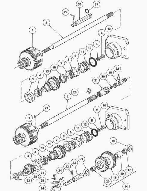
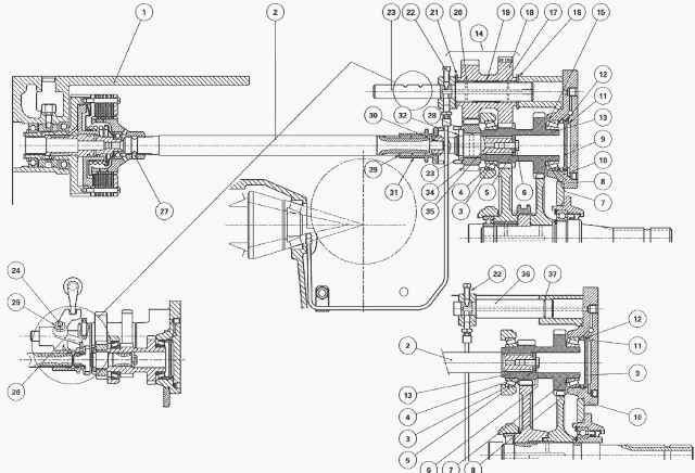
Fig.54. Massey Ferguson 5455, 5465 Tractor 4-speed
PTO
(1) Clutch, (2) Intermediate shaft, (3) Cup, (4) Cone, (5) Washer, (6)
Screw, (7) Cone, (8) Cup, (9) Brake piston, (10) Cover plate, (11)
Shims, (12) "O" ring, (13) Driving gear, (14) Double gear assembly, (15)
Deflector, (16) Washer, (17) Needle roller bearing, (18) Double gear,
(19) Spacer, (20) Needle roller bearing, (21) Washer, (22) Set screw,
(23) Pin, (24) Locking screw, (25) Nut, (32) Circlip, (33) Washer, (34)
Dog gear, (35) Shaft, (26) Fork, (27) Screw, (28) Needle roller bearing,
(29) Circlip, (30) Ring, (31) Dog clutch sleeve
Massey Ferguson 5455, 5465 tractor 4-speed economy PTO (without shimming)
Remove the nut (25) and the locking screw (24) from the fork (26).
Remove the set screw (22).
Take out the pin (23) from the double gear assembly (14) in order to
disengage the fork (26). To release only the fork, pull the pin (23)
back slightly.
Remove the friction washers (16) (21). Take care not to let the washers
to fall into the housing.
Take out the double gear assembly (14) (through the spool valve support
aperture, only for the version without shimming).
Remove the needle roller bearings (17) (20) and the spacer (19) from the
gear (18).
Remove the circlip (32). To facilitate access to the circlip, use
short-handled pliers.
Take out the gear (13) and shaft (35) assembly held in place by the
washer (5) and the screw (6).
Remove the washer with flat section (33). Take care not to let the
washer or the circlip fall into the housing. Hold in place the dog gear
(34) and the needle roller bearing (28). The cone (4) remains in the cup
(3) during removal of the gear.
Remove the dog gear (34) and the needle roller bearing (28).
Remove the bearing cone (4).
Remove the Allen screw (27) (if necessary).
Take out the shaft (2) and the dog clutch sleeve (31) (if necessary).
The circlip (29) remains on the shaft (2).
Check and clean the components. Replace any defective parts.
Install the shaft (2) and the dog clutch sleeve (31) (if removed).
Smear the screw (27) with Loctite 221 and tighten (if removed).
Install the cone (4). Move the gear (13) prepared with the shaft (35)
forwards. Fit the dog gear (34), the needle roller bearing (28), the
washer (33) and the circlip (32).
Push on the gear (13). Position the washer (33). Install the circlip
(32).
In the gear (18), position the spacer (19) and the needle roller
bearings (17) (20). Position the double gear assembly (14). Fit the
washer (16) smeared with miscible grease (Amber Technical or
equivalent).
Check that the channels in the pin (23) are not blocked. They are used
for lubricating the needle roller bearings (17) (20) and the front
bearing of the pinion. Slightly engage the pin (23) in order to hold the
washer (16) in place. Position the washer (21) smeared with miscible
grease. Centre the double gear assembly (14).
Definitively fit the pin (23) into the gear assembly (14) and in the
fork (26) while ensuring the correct positioning of the hole for the set
screw (22).
Smear screw (22) with Loctite 542 and tighten to a torque of 28 - 43 Nm.
Clean the mating face of the cover plate (10).
Smear the mating face of the housing with a sealing product (Loctite 510
or equivalent).
Check for the presence of the cup (8). Tighten the screws (3) to 130-170
Nm.
Reconnect the pipes (1) (2).
Fit the screw (24) and the nut (25) onto the fork (26).
Adjust the locking of the fork (26):
- Position the fork (26), with the locking screw (24) on flat "M" of the
pin (23) (between the two locking slots) and tighten the screw to
compress the ball.
- Loosen the screw by one-quarter turn. Smear the nut (25) with Loctite
241. Tighten to a torque of 15 - 20 Nm.
- Check that the fork locks correctly.
Adjust the control.
Clean the mating face of the spool valve support.
Smear the mating face of the spool valve support cover plate with a
sealing product (Loctite 510 or equivalent).
Install the spool valve support.
Smear the thread of the two lower screws (4) with Loctite 510. Tighten
the 4 screws to a torque of 50 - 70 Nm.
Check PTO and PTO brake operation.
Check tightness:
- of the mating faces (spool valve support, cover plate, linkage cover
plate)
- Hydraulic unions
Massey Ferguson 5455, 5465 tractor 4-speed economy PTO (with shimming)
The shimming J/P is to be carried out when working on the following
components: the gear (13), the deflector (15), the cones (4) (7), the
cups (3) (8), the piston (9) and the cover plate (10). For correct
shimming of the cones (4) (7) and the cups (3) (8), it is necessary to
remove the linkage cover plate.
Remove the linkage cover plate.
Remove the MF 5455, 5465 Tractor power take-off PTO gears.
Separate the gear (13) from the shaft (35) using a press and a suitable
fixture. The friction ring (30) is force fitted into the shaft (35).
Extract the bearing cone (7) and the deflector (15). To extract the cup
(3), the 540/1000 rpm gears must be removed. Partially drain the axle
housing.
Check and clean the components. Replace any defective parts. For correct
lubrication of the ring (30), a deflector (15) is fitted between the
gear (13) and the bearing cone (7), in contact with the cup.
Install the deflector (15) on the gear (13), and press-fit the cone (7)
fully home into the shoulder.
Install the cone (4) into the cup (3). If the cup (3) has been replaced,
refit the 540/1000 rpm gears. Top up the housing oil level.
Preparing and shimming the gear (13).
Take out the gear (13) and assemble it with the shaft (35), then fit the
washer (5) and the screw (6). Tighten the screw to a torque of 50 Nm.
Refit the cone (4), the dog gear (34) and the needle roller bearing
(28).
Install the gear (13) and shaft (35) assembly. Check for the presence of
the dog clutch sleeve (31).
Position the washer (33) and fit the circlip (32).
In the gear (18), position the spacer (19) and the needle roller
bearings (17) (20). Position the double gear assembly (14). Fit the
washer (16) smeared with miscible grease (Amber Technical or
equivalent).
Ensure that the channels in the pin (23) are not blocked; the channels
are used to lubricate the needle roller bearings (17) (20) and the
pinion front bearing. Slightly engage the pin (23) in order to hold the
washer (16) in place. Position the washer (21) smeared with miscible
grease. Centre the double gear assembly (14).
Definitively fit the pin (23) into the gear assembly (14) and in the
fork (26) while ensuring the correct positioning of the hole for the set
screw (22).
Smear the set screw (22) with Loctite 542. Tighten to a torque of 28 -
43 Nm.
Clean the mating face of the cover plate (10).
Smear the mating face of the housing with a sealing product (Loctite 510
or equivalent).
Check for the presence of the cup (8) and fit the cover plate (10) with
the screws (3) and tighten to a torque of 130-170 Nm.
Reconnect the pipes (1) (2).
Fit the locking screw (24) and the nut (25). Adjust the fork (26).
Install the linkage cover plate.
Adjust the economy power take-off PTO control.
Check PTO and PTO brake operation.
Check tightness:
- of the mating faces (spool valve support, cover plate)
- Hydraulic unions
Assembling and adjusting the Massey
Ferguson 5455, 5465 Tractor 4-speed economy PTO control
Move the control lever to the 1550 rpm economy position.
Screw the clevis (1) level with the end of the threaded part of the
cable (6).
Install the clevis (1) onto lever L with the clip (7).
Adjust the sheath end (5) so that the nut (3) is level with the end of
the threaded part.
Tighten nut (4), ensuring that the cable is not pinched.
Place lever M in the 1550 rpm economy position (sleeve meshed with the
dog gear and the fork locked).
Screw the clevis (1) level with the threaded part of the cable (6) and
fit it onto lever using the clip (7). Tighten the nut (2).
Adjust the sheath end (5), while checking that lever remains locked.
Tighten the nuts (3) (4) and check that the cable is not pinched.
Check the locking of the control in the 2000 rpm position (b) and check
for the correct operation of the indicator light on the instrument
panel.
________________________________________________________________________________
________________________________________________________________________________________
 SPECS
SPECS LOADERS
 MAINTENANCE
 PROBLEMS
________________________________________________________________________________________
 MF 1523
 MF 1531
 MF 135
 MF 1547
 MF 1635
________________________________________________________________________________________
________________________________________________________________________________________
 231
231 231S
231S 235
235 240
240 241
241________________________________________________________________________________________
 255
255 265
265 274
274 285
285 375
375________________________________________________________________________________________
________________________________________________________________________________________
 916X Loader
 921X Loader
 926X Loader
 931X Loader
 936X Loader
________________________________________________________________________________________
 941X Loader
 946X Loader
 951X Loader
 956X Loader
 988 Loader
________________________________________________________________________________________
 1655
1655 GS1705
 1742
1742 2635
2635 4608
4608________________________________________________________________________________________
 1080
1080 1100
1100 2615
2615 3050
3050 3060
3060________________________________________________________________________________________
 4708
4708 5455
5455 5450
5450 5610
5610 5613
5613________________________________________________________________________________________
 DL95 Loader
 DL100 Loader
 DL120 Loader
 DL125 Loader
 DL130 Loader
________________________________________________________________________________________
 DL135 Loader
 DL250 Loader
 DL260 Loader
 L90 Loader
 L100 Loader
________________________________________________________________________________________
 6499
6499 7480
7480 7618
7618 7726
7726 1533
1533________________________________________________________________________________________
 2604H
2604H 2607H
2607H 4455
4455 4610M
4610M 4710
4710________________________________________________________________________________________
 L105E Loader
 L210 Loader
 1014 Loader
 1016 Loader
 1462 Loader
________________________________________________________________________________________
 1525 Loader
 1530 Loader
 232 Loader
 838 Loader
 848 Loader
________________________________________________________________________________________
 5712SL
 6713
6713 6715S
6715S 7475
7475 7615
7615________________________________________________________________________________________
 7716
7716 7724
7724 8240
8240 8650
8650 8732
8732________________________________________________________________________________________
 246 Loader
 1036 Loader
 1038 Loader
 1080 Loader
 856 Loader