
________________________________________________________________________________
Massey Ferguson 5445, 5460 Tractor Ground PTO 2WD version
Massey Ferguson 5445, 5460
Tractors may be fitted with ground PTO. Unlike the independent PTO
system where the PTO speed depends on the engine speed, the proportional
PTO is driven by the rear differential pinion and the PTO shaft speed is
proportional to the travel speed of the tractor.
The pinion comprises a gear (31) constantly meshed with either the gear
(16) (2WD). The sliding gear (10) secures the shaft (8) in rotation with
the shaft (18) (2WD). The gear (3) fitted at the end of the shaft (8)
drives the 540 rpm gear on the rear PTO line.
The movement of the sliding gear (10) is obtained by a pad hinged on a
pin fitted on the left in the lower part of the rear axle housing and
controlled by a rod and a cable operated by a lever in the cab.
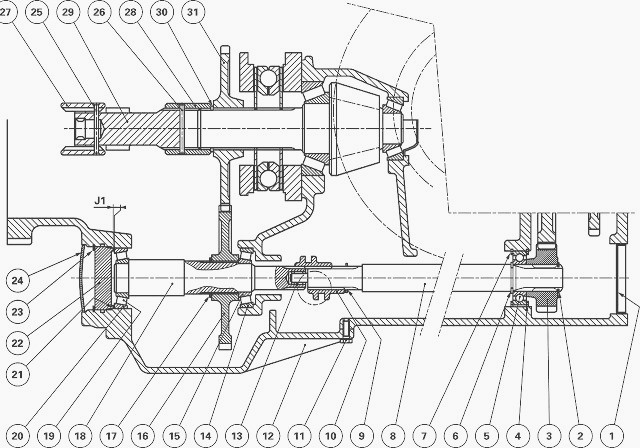
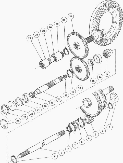
Fig.65. Parts list 2WD
(01) Plug, (02) Circlip, (03) Gear, (04) Circlip, (05) Bearing, (06)
Circlip, (07) Circlip, (08) Shaft, (09) Circlip, (10) Sliding gear, (11)
Screw, (12) Cover plate, (13) Needle roller bearing, (14) Cup, (15)
Cone, (16) Gear, (17) Circlip, (18) 2WD shaft, (19) Cone, (20) Cup, (21)
Shim(s), (22) Spacer, (23) Circlip, (24) Plug, (25) Double pin, (26)
Double pin, (27) Sleeve, (28) Sleeve, (29) Shaft, (30) Circlip, (31)
Gear
Disassembling the MF 5445, 5460
tractor ground PTO (2WD
version)
Chock the tractor. Drain the rear axle housing. Remove the lubrication
pipe from the engine clutch or the Power Shuttle (depending on version)
that is fitted to the lower cover plates of the centre housing and the
gearbox.
Remove the screws (11).
Remove the cover plate (12). Recover the spring (3).
Remove the retainer pipe (4) from the control rod (7) and the detent
plunger (2).
Disconnect the control cable (1) and remove the rod (7). The pad (1) is
free fitted in the centreline of the rod (7).
Remove the "O" ring (5).
Remove the hitch hook. Extract the plug (1).
Remove the circlip (2). Take off the gear (3).
Remove the circlip (4).
Take out the shaft (8) with the bearing (5) and then remove the sleeve
(10). If necessary, remove the circlip (7).
Take off circlips (6) (9).
Extract bearing (5) using a press.
Extract the plug (24).
Take off the circlip (23) and spacer (22).
Remove shims (21). Remove cup (20).
Take out shaft (18) complete with bearing cone (19).
Take off the circlip (17) while supporting the gear (16).
Remove the gear (16) and the cone (15).
Extract the cone (19) and take the circlip (17) off the shaft (18). Pair
up the cones and the cups if they are to be reused. The bearing (13) is
force fitted into the shaft (18).
Extract the cup (14) using a suitable puller. If the gear (31) is
removed, it is necessary to remove the right-hand hydraulic cover plate.
Chock the tractor. Apply the hand brake. Raise the tractor using a jack.
Position the axle stand.
Remove the wheel. Remove the right-hand hydraulic cover plate.
Massey Ferguson 5445, 5460 Tractors with no creeper unit
Drive out the double pins (25) (26) from the coupling sleeves (27) (28).
Slide the sleeves towards each other on the shaft (29).
Remove the shaft and sleeve assembly. Remove the circlip (30).
Remove the gear (31). On 2WD tractors (without proportional PTO) the
gear (31) is absent, but the circlip (30) must still be fitted.
Massey Ferguson 5445, 5460 Tractors with a creeper unit
Remove the fork, the sleeve assembly, the connecting shaft and the
coupler.
Remove the circlip (30). Remove the gear (31).
Reassembling the ground PTO (2WD
version)
If carrying out an operation on the
gear (31)
Tractors with a creeper unit
Install the gear (31).
Install the circlip (30).
Install the fork, the sleeve assembly (28) the connecting shaft and the
coupler. Replace the pins. Adjust the fork.
Tractors with no creeper unit
Install the gear (31).
Install the circlip (30).
Install the assembly (connecting shaft and sleeves) then position the
coupling sleeves (27) (28) on the shaft (29).
Install the double pins (25) (26) on the coupling sleeves. Turn the
sleeve (28. Replace the pins. The long pin is fitted to the sleeve (27).
MF 5445, 5460 Tractors with or without creeper unit
Install the cup (14) up against the shoulder of the housing.
Install the cone (19) on the shaft (18) up against the shoulder, using a
press and a suitable fixture, then position the circlip (17).
Check for the presence of the needle roller bearing (13).
In order to turn the shaft to carry out J1 shimming, do not fit the gear
(16). Position cone (15). Fit shaft (18) assembled with the cone (19)
and circlip (17).
Install the cup (20), the spacer (22) and the circlip (23). For correct
shimming, make sure that the spacer moves freely in the bore of the
housing.
Carry out shimming of the shaft (18) in order to obtain: J1 = 0 to 0.10
mm.
Put a dial gauge feeler pin against the end of spacer (22).
Through the opening of the cover plate (12), pull on the shaft, while
turning it alternately from right to left to correctly seat the cones in
the cups.
Set the dial gauge to zero.
Depending on the clearance measured, select the correct thickness of
shims.
Take off the circlip (23) and spacer (22). Take out shaft (18) assembled
with the cone (19) and circlip (17) while supporting the cone (15).
Refit the gear (16), the shaft (18) and the cup (20).
Apply two spots of grease to the shims (21).
Install the spacer (22) and circlip (23).
Replace or clean the plug (24) and its mating face on the housing.
Smear the corner of the plug housing with Loctite 542 and then fit the
plug.
Place the sliding gear (10) on the shaft (18). Turn the small shoulder E
towards the shaft (18).
Fit circlips (6) (9) on shaft (8).
Using a suitable fixture, fit the bearing (5) using a press onto the
shaft (8), in contact with the circlip (6).
Check for the presence of circlip (7).
Install the assembled shaft (8) in the housing.
Install the circlip (4).
Install the gear (3).
Install the circlip (2).
Check the movement of the sliding gear (10) through the opening of the
cover plate (12).
Replace or clean the plug (1) and its mating face on the housing.
Smear the plug with Loctite 542, then fit it slightly set back from the
face of the housing.
Install the rod (7) (fitted with a new "O" ring (5)) by placing the pad
(1) in the groove of the sliding gear (10).
Clean and degrease the mating faces (cover plate and housing).
Smear the mating face of the cover plate with a sealing product (Master
joint 510 or equivalent).
Screw two opposing guide studs into the housing.
Install the retainer pipe (4), the control rod and the detent plunger
(2) and the spring (3).
Install the cover plate (12) and the lubrication pipe for the engine
clutch or the Power Shuttle (depending on version).
Take out the guide studs. Tighten the screws to a torque of 130 - 170
Nm.
Reconnect the proportional PTO control cable (1).
Adjust the control.
Top up the rear axle oil level.
Install the hitch hook (for tractors fitted with an auto-hitch, check
that it operates correctly).
Check the correct operation of the proportional PTO.
Check tightness:
- of the mating faces
- of the cover plate underneath the rear axle housing
- Hydraulic unions
________________________________________________________________________________
________________________________________________________________________________________
 SPECS
SPECS LOADERS
 MAINTENANCE
 PROBLEMS
________________________________________________________________________________________
 MF 1523
 MF 1531
 MF 135
 MF 1547
 MF 1635
________________________________________________________________________________________
________________________________________________________________________________________
 231
231 231S
231S 235
235 240
240 241
241________________________________________________________________________________________
 255
255 265
265 274
274 285
285 375
375________________________________________________________________________________________
________________________________________________________________________________________
 916X Loader
 921X Loader
 926X Loader
 931X Loader
 936X Loader
________________________________________________________________________________________
 941X Loader
 946X Loader
 951X Loader
 956X Loader
 988 Loader
________________________________________________________________________________________
 1655
1655 GS1705
 1742
1742 2635
2635 4608
4608________________________________________________________________________________________
 1080
1080 1100
1100 2615
2615 3050
3050 3060
3060________________________________________________________________________________________
 4708
4708 5455
5455 5450
5450 5610
5610 5613
5613________________________________________________________________________________________
 DL95 Loader
 DL100 Loader
 DL120 Loader
 DL125 Loader
 DL130 Loader
________________________________________________________________________________________
 DL135 Loader
 DL250 Loader
 DL260 Loader
 L90 Loader
 L100 Loader
________________________________________________________________________________________
 6499
6499 7480
7480 7618
7618 7726
7726 1533
1533________________________________________________________________________________________
 2604H
2604H 2607H
2607H 4455
4455 4610M
4610M 4710
4710________________________________________________________________________________________
 L105E Loader
 L210 Loader
 1014 Loader
 1016 Loader
 1462 Loader
________________________________________________________________________________________
 1525 Loader
 1530 Loader
 232 Loader
 838 Loader
 848 Loader
________________________________________________________________________________________
 5712SL
 6713
6713 6715S
6715S 7475
7475 7615
7615________________________________________________________________________________________
 7716
7716 7724
7724 8240
8240 8650
8650 8732
8732________________________________________________________________________________________
 246 Loader
 1036 Loader
 1038 Loader
 1080 Loader
 856 Loader