
________________________________________________________________________________
1104C Perkins engine - Remove and refit the injection pump (MF 5400, 6400 tractors)
Removing the injection pump
Delphi DP210 pump
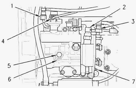
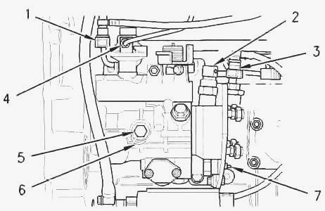
Take off the adjacent components. Check the position of the first
cylinder piston in compression at Top Dead Centre. Loosen the lock screw
(5). Turn the spacer (6) to allow the lock screw (5) to lock the pump
pin. Turn the pump pin anti-clockwise until slight resistance is felt
(Fig. 13). Tighten the lock screw to a torque of 17 Nm. The lock screw
(5) must be tightened to prevent the pump pin from turning. The pump pin
must not turn when the pump is removed.
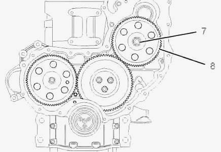
Disconnect the fuel return line (1) (Fig. 13). Disconnect the fuel
supply line (3). Disconnect the connector (2) of the injection timing
solenoid (7). Remove the nut and retaining washer from the injection
pump gear. Extract the pump gear (9) using a suitable puller. Do not try
to extract the gear (8) by inserting a lever between the gear and the
housing. Take out the nut and screw. If necessary, take out the screw
(15) and the bracket (11) from the 1104 Perkins engine block. Take out
the screws (13) to remove the injection pump. Remove the injection pump.
Take off and discard the "O" ring (10).
Bosch VE10 pump
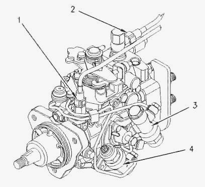
Take off the adjacent components. Check the position of the first
cylinder piston in compression at Top Dead Centre. Mark and disconnect
the fuel pipes (1) and (2) from the injection pump (Fig. 16). Plug the
unions to keep dust out of the channels. Disconnect the injection timing
system connector (3). Disconnect the 1104C Perkins diesel engine stop
solenoid connector (4) (Fig. 16). Loosen the lock screw. Shift the
spacer to allow the lock screw to lock the pump pin. Turn the pump pin
anti-clockwise until slight resistance is felt. Tighten the screw to a
torque of 31 Nm. The lock screw (6) must be tightened to prevent the
pump pin from turning. The pump pin must not turn when the pump is
removed.

Remove the nut (7) and retaining washer from the injection pump gear
(8). Extract the pump gear (9) using a suitable puller. Do not try to
extract the gear (8) by inserting a lever between the gear and the
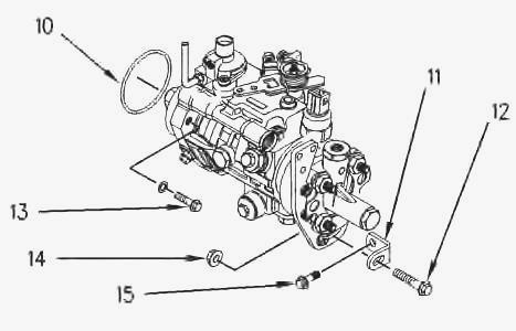
housing. Take out the nut (13) and screw (11) (Fig. 18). If necessary,
remove the bracket (10) and its screws from the 1104 engine block. Take
out the screws (12) to remove the injection pump. Remove the injection
pump. Take off and discard the "O" ring (9).
Refitting the injection pump (4-cylinder Perkins engine)
Delphi DP210 pump
The injection pump must be locked in rotation by the lock screw (5)
during reassembly. Do not loosen this screw before being instructed to
do so. If the lock screw has been loosened or if the pump shaft has
turned, contact a Perkins agent. Check the position of the first
cylinder piston in compression at Top Dead Centre. Do not lubricate the
"O" ring (10) (Fig. 19): it should be dry fitted. Fit a new "O" ring
(10) on the injection pump. Position the injection pump on the housing.
Refit the screws (13). Tighten the screws to 25 Nm. Refit the screw (15)
and bracket (11) if removed.
Check that the bracket properly supports the pump alone. Tighten the
screw (15) to 44 Nm. Refit the screw (12) and the nut (14). Ensure the
contact faces between the pump shaft and injection pump gear are clean.
Lubricate the threads of the pump shaft. The nut (8) should turn freely
until it reaches the gear. Position the injection pump gear on the pump
shaft. Refit the washer and nut (8). Turn the pump gear anti-clockwise
until there is no backlash. Tighten the nut to a torque of 24 Nm.
Reconnect all electrical connectors to the pump. Remove all dustproof
plugs and ensure the channels and unions are clean.
Refit the previously removed fuel channels (1) (3) and (4) (Fig. 20).
Loosen the lock screw (5). Move the spacer (6) so that it no longer
blocks the pump pin by tightening the screw (5). Tighten the screw to a
torque of 12 Nm. The spacer (6) must be correctly positioned and the
screw (5) correctly tightened to prevent contact between the injection
pump shaft and the screw (5). Tighten the nut (8) to a torque of 88 Nm.
Reassemble the adjacent components (injection channels, front cover
plate, fan, belts, crankshaft pulley).
Bosch VE10 pump
Check the position of the first cylinder piston in compression at Top
Dead Centre. Lightly lubricate a new "O" ring (9) with silicone oil. Fit
the new seal (9) to the pump. Position the injection pump on the
housing. Refit the screws (12). Tighten the screws to 25 Nm. Refit the
screw and bracket (10) if removed. Check that the bracket properly
supports the pump alone. Tighten the screw to a torque of 44 Nm. Refit
the screw (11) and the nut (13). Ensure the contact faces between the
pump shaft and injection pump gear are clean. Lubricate the threads of
the pump shaft. The nut (7) should turn freely until it reaches the gear
(8) (Fig. 23).

Position the injection pump gear on the pump shaft. Refit the washer and
nut (7). Turn the pump gear anti-clockwise until there is no backlash.
Tighten the nut to a torque of 24 Nm. Reconnect all electrical
connectors to the pump (Fig. 24). Remove all dustproof plugs and ensure
the channels and unions are clean. Refit the previously removed fuel
channels (1) (2) (Fig. 24).
Loosen the lock screw (6). Move the spacer (5) so that it no longer
blocks the pump pin by tightening the screw (6). Tighten the screw to a
torque of 12 Nm. The spacer (5) must be correctly positioned and the
screw (6) correctly tightened to prevent contact between the injection
pump shaft and the screw (6). Tighten the nut (7) to a torque of 88 Nm
(Fig. 23). Reassemble the adjacent components (injection channels, front
cover plate, fan, belts, crankshaft pulley).
________________________________________________________________________________
________________________________________________________________________________________
 SPECS
SPECS LOADERS
 MAINTENANCE
 PROBLEMS
________________________________________________________________________________________
 MF 1523
 MF 1531
 MF 135
 MF 1547
 MF 1635
________________________________________________________________________________________
________________________________________________________________________________________
 231
231 231S
231S 235
235 240
240 241
241________________________________________________________________________________________
 255
255 265
265 274
274 285
285 375
375________________________________________________________________________________________
________________________________________________________________________________________
 916X Loader
 921X Loader
 926X Loader
 931X Loader
 936X Loader
________________________________________________________________________________________
 941X Loader
 946X Loader
 951X Loader
 956X Loader
 988 Loader
________________________________________________________________________________________
 1655
1655 GS1705
 1742
1742 2635
2635 4608
4608________________________________________________________________________________________
 1080
1080 1100
1100 2615
2615 3050
3050 3060
3060________________________________________________________________________________________
 4708
4708 5455
5455 5450
5450 5610
5610 5613
5613________________________________________________________________________________________
 DL95 Loader
 DL100 Loader
 DL120 Loader
 DL125 Loader
 DL130 Loader
________________________________________________________________________________________
 DL135 Loader
 DL250 Loader
 DL260 Loader
 L90 Loader
 L100 Loader
________________________________________________________________________________________
 6499
6499 7480
7480 7618
7618 7726
7726 1533
1533________________________________________________________________________________________
 2604H
2604H 2607H
2607H 4455
4455 4610M
4610M 4710
4710________________________________________________________________________________________
 L105E Loader
 L210 Loader
 1014 Loader
 1016 Loader
 1462 Loader
________________________________________________________________________________________
 1525 Loader
 1530 Loader
 232 Loader
 838 Loader
 848 Loader
________________________________________________________________________________________
 5712SL
 6713
6713 6715S
6715S 7475
7475 7615
7615________________________________________________________________________________________
 7716
7716 7724
7724 8240
8240 8650
8650 8732
8732________________________________________________________________________________________
 246 Loader
 1036 Loader
 1038 Loader
 1080 Loader
 856 Loader