
________________________________________________________________________________
1106 Perkins Motor - Connecting Rod and Piston Ring (Inspect and adjust)
Inspect the Piston and the Piston Rings - Check the piston for wear and
other damage. Check that the piston rings are free to move in the
grooves and that the rings are not broken.
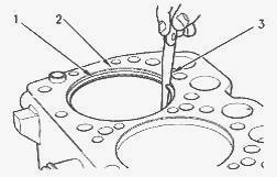
(1) Feeler gauge (2) Piston ring (3) Piston grooves
Inspect the Clearance of the Piston Ring - Remove the piston rings and
clean the grooves and the piston rings. Fit new piston rings (2) in the
piston grooves (3). Check the clearance for the piston ring by placing a
suitable feeler gauge (1) between piston groove (3) and the top of
piston ring (2).
(1) Piston ring (2) Cylinder ring ridge (3) Feeler gauge
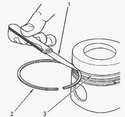
Inspect the Piston Ring End Gap - Clean all carbon from the top of the
1106 Perkins cylinder bores. Place each piston ring (1) in the cylinder
bore just below the cylinder ring ridge (2). Use a suitable feeler gauge
(3) to measure piston ring end gap. The coil spring must be removed from
the oil control ring before the gap of the oil control ring is measured.
Connecting Rod Inspect
These procedures determine the following characteristics of the
connecting rod - The length of the connecting rod. The distortion of the
connecting rod. The parallel alignment of the bores of the connecting
rod. If the crankshaft or the 1106 Perkins cylinder block are replaced,
the piston height for all cylinders must be measured. The grade of
length of the connecting rods may need to be changed in order to obtain
the correct piston height.
If the grade of length must be changed, one of the following actions
must be taken: New connecting rod assemblies that are the correct grade
of length must be installed. New piston pin bearings must be bored after
installation in the original connecting rods. When the piston pin is
installed, always install new retaining rings on each end of the piston
pin. If the piston pin cannot be removed by hand, heat the piston to a
temperature of 45±5C (113±9F) in order to aid the removal of the piston
pin. Heating the piston to this temperature may also aid the
installation of the piston pin.
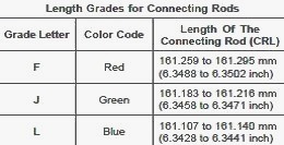
Length of The Connecting Rod
The connecting rod length (CRL) is the length of the connecting rod.
Refer to Table for each grade of length of connecting rod. In order to
ensure that the piston height above the 1106D Perkins cylinder block is
correct, three grades of connecting rods “F” to “L” are used during
manufacture at the factory.
Replacement connecting rods are available in
three grades. These grades of connecting rod are “F” to “L”. The grade
of length is identified by a letter or a color which is marked on the
side of the connecting rod. The longest grade is marked with the letter
“F”. The shortest grade is marked with the letter “L”.
The difference in length between each grade of connecting rods is the
following value: 0.076 mm (0.0030 inch) The grade of length of a
connecting rod is
determined in the factory by machining an eccentric hole in a
semi-finished piston pin bushing.
Therefore, the grade of length is
determined by the position of the
center of the hole in the piston pin bearing. If the connecting rod must
be replaced, a new connecting rod assembly must be purchased and
installed. A new
piston pin bearing is installed in the new connecting rod at the
factory. The bore of the piston pin bearing is reamed to the correct
eccentricity.
Piston Pin Bearings
If the piston pin bearing requires replacement but the original
connecting rod is not replaced, the following procedures must be
performed: Determine the grade of
length of the connecting rod. Use one of the following characteristics:
The mark, The color, Measuring the length.
Ensure that the connecting rod is aligned parallel and that the
connecting rod is not distorted. Remove the piston pin bearing from the
connecting rod. Install a
new bearing in the connecting rod. The new bearing is partially
finished. The new bearing must be bored off-center to the correct
diameter. This off-center
position is determined by the grade of length of the connecting rod.
Surface finish of the bored hole in the piston pin bearing Ra 0.8
micrometers.
Machine the ends of the piston pin bearing to the correct length. Remove
any sharp edges. If the grade of length of the connecting rod is
changed, the letter that
is stamped on the connecting rod must be removed. Each a letter that is
for the new grade of length on the side of the connecting rod. Do not
stamp a new letter
on the connecting rod. The force of stamping may damage the connecting
rod.
Measure The Length Of The Connecting Rod - If the mark or the color of
the grade of length cannot be observed on the connecting rod, perform
the following
procedure:
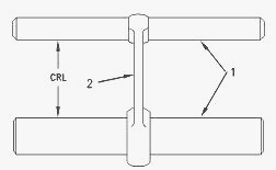
(1) Measuring pins (2) Connecting rod (CRL) Connecting Rod Length
Use the following tools in order to measure the length of the connecting
rod: Appropriate gauges for measuring distance, Measuring pins (1).
Ensure that the
measuring pins (1) are parallel. “CRL” is measured when the bearing for
the crankshaft journal is removed and the original piston pin bearing is
installed.
Distortion of The Connecting Rod - Use the following tools in order to
measure the distances for the connecting rod (2) which are specified in
illustration:
Appropriate gauges for measuring distance, Measuring pins (1).
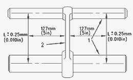
(1) Measuring pins (2) Connecting rod (L) The length between the centers
of the piston pin bearing and the crankshaft journal bearing is shown in
illustration.
Measure the connecting rod for distortion and parallel alignment between
the bores. The bores for the crankshaft bearing and the bearing for the
piston pin must
be square and parallel with each other within the required limits. If
the piston pin bearing is removed, the limit “L” is the following value:
± 0.25 mm (± 0.010 inch).
The limits are measured at a distance of 127 mm (5.0 inch) from each
side of the connecting rod. If the piston pin bearing is not removed,
the limit “L” is the
following value: ± 0.06 mm (± 0.0024 inch) L is equal to 219.08 ±
0.03mm(8.625 ± 0.001 inch). Inspect the piston pin bearing and the
piston pin for wear.
Measure the clearance of the piston pin in the piston pin bearing.
________________________________________________________________________________
________________________________________________________________________________________
 SPECS
SPECS LOADERS
 MAINTENANCE
 PROBLEMS
________________________________________________________________________________________
 MF 1523
 MF 1531
 MF 135
 MF 1547
 MF 1635
________________________________________________________________________________________
________________________________________________________________________________________
 231
231 231S
231S 235
235 240
240 241
241________________________________________________________________________________________
 255
255 265
265 274
274 285
285 375
375________________________________________________________________________________________
________________________________________________________________________________________
 916X Loader
 921X Loader
 926X Loader
 931X Loader
 936X Loader
________________________________________________________________________________________
 941X Loader
 946X Loader
 951X Loader
 956X Loader
 988 Loader
________________________________________________________________________________________
 1655
1655 GS1705
 1742
1742 2635
2635 4608
4608________________________________________________________________________________________
 1080
1080 1100
1100 2615
2615 3050
3050 3060
3060________________________________________________________________________________________
 4708
4708 5455
5455 5450
5450 5610
5610 5613
5613________________________________________________________________________________________
 DL95 Loader
 DL100 Loader
 DL120 Loader
 DL125 Loader
 DL130 Loader
________________________________________________________________________________________
 DL135 Loader
 DL250 Loader
 DL260 Loader
 L90 Loader
 L100 Loader
________________________________________________________________________________________
 6499
6499 7480
7480 7618
7618 7726
7726 1533
1533________________________________________________________________________________________
 2604H
2604H 2607H
2607H 4455
4455 4610M
4610M 4710
4710________________________________________________________________________________________
 L105E Loader
 L210 Loader
 1014 Loader
 1016 Loader
 1462 Loader
________________________________________________________________________________________
 1525 Loader
 1530 Loader
 232 Loader
 838 Loader
 848 Loader
________________________________________________________________________________________
 5712SL
 6713
6713 6715S
6715S 7475
7475 7615
7615________________________________________________________________________________________
 7716
7716 7724
7724 8240
8240 8650
8650 8732
8732________________________________________________________________________________________
 246 Loader
 1036 Loader
 1038 Loader
 1080 Loader
 856 Loader