
________________________________________________________________________________
1106 Perkins engine - Exhaust Manifold and Inlet Manifold (Remove and Install)
Exhaust Manifold
Removal Procedure (Side Mounted)
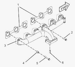
Remove the turbocharger. Loosen the setscrews (2) and (5) in reverse
numerical order. This will help prevent distortion of the exhaust
manifold. Remove the center four setscrews (2) from the exhaust manifold
(3). Remove the outer eight setscrews (5) and the spacers (4) from the
exhaust manifold (3).
Support the manifold as the setscrews are removed. Remove the exhaust
manifold (3). Remove the two exhaust manifold gaskets (1). Discard the
gaskets. If necessary, remove the four studs (6) from the exhaust
manifold (3).
Removal Procedure (Top Mounted)
Disconnect all hoses, tube assemblies and wire leads from the 1106
Perkins turbocharger. Loosen the setscrews (2) and (5) in reverse
numerical order. Remove the center four setscrews (2) from the exhaust
manifold (3). Remove the outer eight setscrews (5) and the spacers (4)
from the exhaust manifold (3).
Remove the assembly of the exhaust manifold (3) and the turbocharger.
Remove the two exhaust manifold gaskets (1). Discard the gaskets. Remove
the turbocharger from the exhaust manifold (3). If necessary, remove the
four studs (6) from the exhaust manifold (3).
Installation Procedure (Side Mounted)
See Remove procedure illustrations. Ensure that the exhaust manifold is
clean and free from damage. If necessary, replace the exhaust manifold.
Clean the joint face of the cylinder head. If necessary, install the
four studs (6) to the exhaust manifold (3). Tighten the studs to a
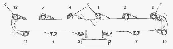
torque of 18 Nm (13 lb ft). Install Tooling to the cylinder head in the
positions (X). Position two new exhaust manifold gaskets (1) onto
Tooling. Ensure that the word TOP is outward and upward.
Align the exhaust manifold (3) with Tooling. Install the exhaust
manifold to the cylinder head. If the setscrews (2) and (5) have been
previously used, the setscrews should be thoroughly cleaned. Tooling
should be applied to the first two threads of the setscrews.
Install the setscrews (2) finger tight. Install the setscrews (5) and
the spacers (4) finger tight. Remove Tooling. Install the remaining
setscrews (2) finger tight. Install the remaining setscrews (5) and
spacers (4) finger tight. Tighten the setscrews (2) and (5) to a torque
of 44 Nm (32 lb ft). Tighten the setscrews in the sequence that is shown
in Illustration.
Installation Procedure (Top Mounted)
See Remove procedure illustrations. Ensure that the exhaust manifold is
clean and free from damage. If necessary, replace the exhaust manifold.
Clean the joint face of the cylinder head. If necessary, install the
four studs (6) to the exhaust manifold (3). Tighten the studs to a
torque of 18 Nm (13 lb ft). Install the 1106 Perkins turbocharger to the
exhaust manifold. Install Tooling to the cylinder head in the positions
(X).
Position two new exhaust manifold gaskets (1) onto Tooling. Align the
exhaust manifold (3) with Tooling. Install the exhaust manifold to the
cylinder head. If the setscrews (2) and (5) have been previously used,
the setscrews should be thoroughly cleaned. Tooling should be applied to
the first two threads of the setscrews. Do not apply Tooling to new
setscrews.
Install the setscrews (2) finger tight. Install the setscrews (5) and
the spacers (4) finger tight. Remove Tooling. Install the remaining
setscrews (2) finger tight. Install the remaining setscrews (5) and
spacers (4) finger tight. Tighten the setscrews (2) and (5) to a torque
of 44 Nm (32 lb ft). Tighten the setscrews in the sequence that is shown
in Illustration. Connect all hoses, tube assemblies and wire leads from
the turbocharger.
Inlet Manifold
If necessary, remove the fuel filter base. Remove the fuel manifold.
Remove the ECM mounting bracket. Remove the boost pressure sensor.
Remove the air inlet temperature sensor. Disconnect the breather hose
from the separator for the crankcase breather.
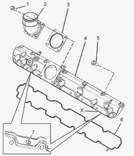
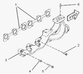
Cut the cable ties that secure the harness assembly to the inlet
manifold (4). Position the harness assembly away from the inlet
manifold. Remove the setscrews (1) from the inlet connection (2). Remove
the inlet connection (2) and the gasket (3) from the inlet manifold (4).
Discard the gasket. Remove the setscrews (5). Remove the inlet manifold
(4) from the cylinder head. Use a suitable tool to pry the inlet
manifold from the cylinder head. Use the recess at
position (X) to pry the inlet manifold. Remove the inlet manifold seal
(6) from the recess in the inlet manifold (4). Discard the seal. Do not
remove the two dowel pins (7).
Ensure that the inlet manifold is clean and free from damage. If
necessary, replace the inlet manifold. If a new inlet manifold is
installed, install two new dowel pins (7) to the inlet manifold (4). Do
not install dowel pins to the 1106 Perkins cylinder head. Clean the
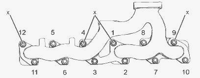
joint face of the cylinder head. Align the tag (8) to the slot at
position (Y) on the inlet manifold. Install the new seal (6) to the
groove in the inlet manifold (4). Ensure that the seal is correctly
located. Align the dowel pins (7) to the holes in the cylinder head.
Install the inlet manifold (4) to the cylinder head. Apply Tooling to
the setscrews (5). Install the setscrews to the inlet manifold (4).
Tighten the setscrews to a torque of 22 Nm (16 lb ft) in the sequence
that is shown in Illustration. Ensure that the inlet connection (2) is
clean and free from damage. If necessary, replace the inlet connection.
Position a new gasket (3) onto the inlet manifold. Install the inlet
connection (2) to the inlet manifold (4). Install setscrews (1) to the
inlet connection (2). Tighten the setscrews to a torque of 22 Nm (16 lb
ft). Install the air temperature sensor. Install the boost pressure
sensor.
Position the harness assembly on the inlet manifold. Use new cable ties
in order to secure the harness assembly. Connect the breather hose to
the separator for the crankcase breather. Install the ECM mounting
bracket. Install the fuel manifold. If necessary, install the fuel
filter base.
________________________________________________________________________________
________________________________________________________________________________________
 SPECS
SPECS LOADERS
 MAINTENANCE
 PROBLEMS
________________________________________________________________________________________
 MF 1523
 MF 1531
 MF 135
 MF 1547
 MF 1635
________________________________________________________________________________________
________________________________________________________________________________________
 231
231 231S
231S 235
235 240
240 241
241________________________________________________________________________________________
 255
255 265
265 274
274 285
285 375
375________________________________________________________________________________________
________________________________________________________________________________________
 916X Loader
 921X Loader
 926X Loader
 931X Loader
 936X Loader
________________________________________________________________________________________
 941X Loader
 946X Loader
 951X Loader
 956X Loader
 988 Loader
________________________________________________________________________________________
 1655
1655 GS1705
 1742
1742 2635
2635 4608
4608________________________________________________________________________________________
 1080
1080 1100
1100 2615
2615 3050
3050 3060
3060________________________________________________________________________________________
 4708
4708 5455
5455 5450
5450 5610
5610 5613
5613________________________________________________________________________________________
 DL95 Loader
 DL100 Loader
 DL120 Loader
 DL125 Loader
 DL130 Loader
________________________________________________________________________________________
 DL135 Loader
 DL250 Loader
 DL260 Loader
 L90 Loader
 L100 Loader
________________________________________________________________________________________
 6499
6499 7480
7480 7618
7618 7726
7726 1533
1533________________________________________________________________________________________
 2604H
2604H 2607H
2607H 4455
4455 4610M
4610M 4710
4710________________________________________________________________________________________
 L105E Loader
 L210 Loader
 1014 Loader
 1016 Loader
 1462 Loader
________________________________________________________________________________________
 1525 Loader
 1530 Loader
 232 Loader
 838 Loader
 848 Loader
________________________________________________________________________________________
 5712SL
 6713
6713 6715S
6715S 7475
7475 7615
7615________________________________________________________________________________________
 7716
7716 7724
7724 8240
8240 8650
8650 8732
8732________________________________________________________________________________________
 246 Loader
 1036 Loader
 1038 Loader
 1080 Loader
 856 Loader