
________________________________________________________________________________
Perkins 1106 motor - Flywheel and Damper (Inspect and adjust)
Alignment of the Flywheel Face - Set the pointer of the dial indicator
to 0 mm (0 inch). Turn the flywheel. Read the dial indicator for every
45 degrees. During the check, keep the crankshaft pressed toward the
front of the 1106 Perkins engine in order to remove any end clearance.
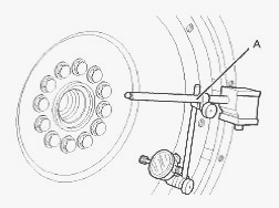
Calculate the difference between the lowest measurement and the highest
measurement of the four locations. This difference must not be greater
than 0.03 mm (0.001 inch) for every 25 mm (1.0 inch) of the radius of
the flywheel. The radius of the flywheel is measured from the axis of
the crankshaft to the contact point of the dial indicator.
Flywheel Runout - Set the pointer of the dial indicator to 0 mm (0
inch). Turn the flywheel. Read the dial indicator for every 45 degrees.
Calculate the difference between the lowest measurement and the highest
measurement of the four locations. This difference must not be greater
than 0.30 mm (0.012 inch).
Concentricity and Alignment of the Flywheel Housing - This check must be
made with the flywheel and the starter removed and the bolts for the
flywheel housing tightened lightly. Set the pointer of the dial
indicator to 0 mm (0 inch). Check the concentricity at intervals of 45
degrees around the flywheel housing.
Calculate the difference between the lowest measurement and the highest
measurement. This difference must not be greater than the limit that is
given in Table. Any necessary adjustment must be made on the flywheel
housing. Then, recheck the concentricity.
Inspect the Gear Group - Inspect the gears for wear or for damage. If
the gears are worn or damaged, use new parts for replacement.
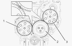
(1) Camshaft gear (2) Idler gear (3) Fuel injection pump gear
(4) Crankshaft gear
Measure the backlash between the camshaft gear (1) and the idler gear
(2). Measure the backlash between the idler gear (2) and the crankshaft
gear (4). Measure the backlash between the fuel injection pump gear (3)
and the idler gear (2). Measure the end play on idler gear (2).
Vibration Damper adjust - The vibration damper is installed on the front
of the crankshaft. There are two types of hub assembly that can be
installed to this engine. The vibration damper is installed in order to
help remove torsional vibration in the 1106D Perkins motor.
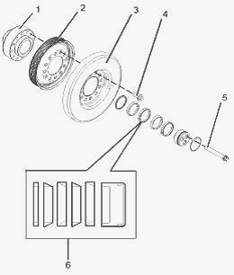
(1) Crankshaft adapter (2) Pulley (3) Vibration damper (4)
Damper setscrews (5) Setscrews for the adapter (6) Hub assembly
Vibration damper with out hub assembly - Replace the vibration damper if
any of the following conditions exist: There is any impact damage to the
outer casing. There is leakage of the viscous fluid from the cover
plate. There is movement of the pulley or the outer ring on the hub.
There is a large amount of gear train wear that is not caused by lack of
oil. Analysis of the engine oil has revealed that the front main bearing
is badly worn. The 1106 Perkins engine has had a failure because of a
broken crankshaft.
Check the areas around the holes for the bolts in the vibration damper
for cracks or for wear and for damage. Use the following steps in order
to check the alignment and the runout of the vibration damper: Remove
any debris from the front face of the vibration damper. Remove any
debris from the circumference of the vibration damper. Mount the dial
indicator on the front cover. Use the dial indicator to measure the
outer face of the vibration damper. Set the dial indicator to read 0.00
mm (0.00 inch).
Rotate the crankshaft at intervals of 45 degrees and read the dial
indicator. The difference between the lower measurements and the higher
measurements that are read on the dial indicator at all four points must
not be more than 0.18 mm (0.007 inch).
If the reading on the dial indicator is more than 0.18 mm (0.007 inch),
inspect the pulley and the vibration damper for damage. If the pulley or
the vibration damper are damaged, use new parts for replacement. Move
the dial indicator so that the dial indicator will measure the
circumference of the vibration damper. Set the dial indicator to read
0.00 mm (0.00 inch).
Slowly rotate the crankshaft in order to measure the runout of the
circumference of the vibration damper. Use the highest reading and the
lowest reading on the dial indicator. The maximum and the minimum
readings on the dial indicator should not vary more than 0.12 mm (0.005
inch).
If the reading on the dial indicator is more than 0.12 mm (0.005 inch),
inspect the pulley and the vibration damper for damage. If the pulley or
the vibration damper are damaged, use new parts for replacement.
________________________________________________________________________________
________________________________________________________________________________________
 SPECS
SPECS LOADERS
 MAINTENANCE
 PROBLEMS
________________________________________________________________________________________
 MF 1523
 MF 1531
 MF 135
 MF 1547
 MF 1635
________________________________________________________________________________________
________________________________________________________________________________________
 231
231 231S
231S 235
235 240
240 241
241________________________________________________________________________________________
 255
255 265
265 274
274 285
285 375
375________________________________________________________________________________________
________________________________________________________________________________________
 916X Loader
 921X Loader
 926X Loader
 931X Loader
 936X Loader
________________________________________________________________________________________
 941X Loader
 946X Loader
 951X Loader
 956X Loader
 988 Loader
________________________________________________________________________________________
 1655
1655 GS1705
 1742
1742 2635
2635 4608
4608________________________________________________________________________________________
 1080
1080 1100
1100 2615
2615 3050
3050 3060
3060________________________________________________________________________________________
 4708
4708 5455
5455 5450
5450 5610
5610 5613
5613________________________________________________________________________________________
 DL95 Loader
 DL100 Loader
 DL120 Loader
 DL125 Loader
 DL130 Loader
________________________________________________________________________________________
 DL135 Loader
 DL250 Loader
 DL260 Loader
 L90 Loader
 L100 Loader
________________________________________________________________________________________
 6499
6499 7480
7480 7618
7618 7726
7726 1533
1533________________________________________________________________________________________
 2604H
2604H 2607H
2607H 4455
4455 4610M
4610M 4710
4710________________________________________________________________________________________
 L105E Loader
 L210 Loader
 1014 Loader
 1016 Loader
 1462 Loader
________________________________________________________________________________________
 1525 Loader
 1530 Loader
 232 Loader
 838 Loader
 848 Loader
________________________________________________________________________________________
 5712SL
 6713
6713 6715S
6715S 7475
7475 7615
7615________________________________________________________________________________________
 7716
7716 7724
7724 8240
8240 8650
8650 8732
8732________________________________________________________________________________________
 246 Loader
 1036 Loader
 1038 Loader
 1080 Loader
 856 Loader