
________________________________________________________________________________
1106 Perkins Engine - Oil Pan (Remove and Install)
Engine Oil Pan (Aluminum)
Remove the flywheel housing.
Place a suitable container below the 1106 Perkins engine oil pan (7).
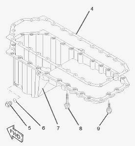
Remove:
- the drain plug (5) and drain the engine lubricating oil. Clean up any
spillage of oil immediately.
- the O-ring seal (6) from the drain plug (5). Discard the O-ring seal.
Disconnect the breather hose (not shown) from the clip that secures the
hose to the engine oil pan. Position the breather hose away from the
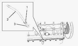
engine oil pan. If necessary, remove the assembly of dipstick tube.
Loosen the nut (1) and remove the tube assembly (2).
- the seal (3) from the tube assembly. Discard the seal. Identify the
position and orientation of the tube assembly.
Support the assembly of the engine oil pan. Loosen the long isolating
screws (8) and the two short isolating screws (9). Mark the position of
the clip that secures the breather hose (not shown).
- the clip. The isolating screws are held captive by the joint (1).
- the assembly of the engine oil pan from the tractor engine.
- the isolating screws (8) and (9) from the engine oil pan (7).
- the joint (4) from the engine oil pan (7). Discard the joint. If
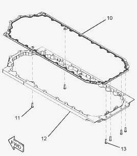
necessary, follow Steps to remove the isolating frame from the cylinder
block. Support the isolating frame (12). Use Tooling to remove the torx
screws (11) and (13).
- the isolating frame (12) from the cylinder block.
- the joint (10). Discard the joint.
Install Tooling to positions (X) in the cylinder block. If necessary,
follow Steps to install the isolating frame. Ensure that the joint face
of the cylinder block is clean and free from damage. Ensure that the
isolating frame is clean and free from damage. If necessary, replace the
isolating frame. Apply a bead of Tooling to positions (Y).
Position a new joint (10) onto the isolating frame (12). Align the
isolating frame (10) with Tooling. Install:
- the isolating frame to the cylinder block. Use Tooling to install the
two torx screws (11) and the four torx screws (13) to the isolating
frame. Tighten the torx screws (11) to a torque of 22 Nm (16 lb ft).
Tighten the torx screws (13) to a torque of 22 Nm (16 lb ft). Ensure
that the engine oil pan (7) is clean and free from damage. Clean the
isolating screws (8) and (9). Inspect the isolating screws for
deterioration or damage. If necessary, replace the isolating screws. If
necessary, ensure that the joint face of the isolating frame is clean.
The isolating screws must be replaced as a complete set in order to
ensure the correct clamping of the engine oil pan. Position a new joint
(4) onto the engine oil pan (7).
- the isolating screws (8) and (9) to the engine oil pan. Do not install
the isolating screws (8) in positions (X). Refer to Illustration. The
isolating screws are held captive by the joint. Align the assembly of
the engine oil pan with Tooling.
- the assembly of the engine oil pan to the isolating frame (12).
Install the clip that secures the breather hose (not shown) in the
correct position. (X) - Position of guide studs. (Z) - Position of short
isolating screws. Tighten the isolating screws to a torque of 22 Nm (16
lb ft). Tighten the isolating screws in the sequence that is shown in
Illustration. Remove Tooling.
- the four remaining isolating screws. Tighten the isolating screws to a
torque of 22 Nm(16 lb ft). Tighten the isolating screws in the sequence
that is shown in Illustration.
- a new O-ring seal (6) to the drain plug (5).
- the drain plug (5) to the engine oil pan (7). Refer to Illustration.
Tighten the oil drain plug to a torque of 34 Nm (25 lb ft). If
necessary, follow Steps to install the assembly of the dipstick tube.
- a new seal (3) to the tube assembly (2). Apply Tooling to the nut (1).
- the tube assembly to the engine oil pan. Ensure that the orientation
of the tube assembly is correct. Tighten the nut (1) to a torque of 18
N·m (13 lb ft).
- the dipstick. Fill the engine oil pan to the correct level.
- If necessary, install the flywheel housing.
Engine Oil Pan (Cast Iron)
The 1106 Perkins engine should be mounted in a suitable stand and placed
in the inverted position. Disconnect the breather hose (not shown) from
the clip that secures the hose to the engine oil pan. Position the
breather hose away from the engine oil pan.
If necessary, remove the assembly of dipstick tube. Loosen the nut (1)
and remove the tube assembly (2). Remove:
- the seal (3) from the tube assembly. Discard the seal. Identify the
position and orientation of the tube assembly. Attach a suitable lifting
device to the engine oil pan (7) and support the weight of the engine
oil pan. The engine oil pan can weigh 100 kg (220 lb). Use Tooling in
order to remove the four torx screws (11).
- the nuts (10).
- the setscrews (8) and (9). The setscrews are different lengths. Note
the position of the different setscrews. Use the lifting device to
remove the engine oil pan (7) from the cylinder block.
- the joint (4) from the cylinder block. Discard the joint.
- the drain plug (5).
- the O-ring seal (6) from the oil drain plug (5). Discard the O-ring
seal.
Ensure that the joint face of the cylinder block is clean and free from
damage. Inspect the studs in the cylinder block (not show) for damage.
If necessary, replace the studs. Ensure that the engine oil pan is clean
and free from damage. Apply a bead of Tooling to positions (Y).
Align a new joint (4) with the studs (not shown) and install the joint
to the cylinder block. Attach a suitable lifting device to the engine
oil pan (7). The engine oil pan can weigh 100 kg (220 lb). Use the
lifting device to align the engine oil pan (7) with the studs (not
shown).
Install:
- the 1106D Perkins engine oil pan to the cylinder block.
- the setscrews (8) and (9), the nuts (10) and the torx screws (11)
finger tight. Align the rear face of the engine oil pan to the rear face
of the cylinder block. Use Tooling and a feeler gauge in order to check
the alignment between the engine oil pan and the cylinder block. Tighten
the setscrews (8) and the nuts (10) to a torque of 22 Nm (16 lb ft).
Tighten the fasteners in the sequence that is shown in Illustration.
Tighten the remaining setscrews to a torque of 22 Nm (16 lb ft). Tighten
the setscrews in the sequence that is shown in Illustration. Use Tooling
to tighten the torx screws to a torque of 22 Nm (16 lb ft). Refer to
Illustration.
- a new O-ring seal (6) to the drain plug (5).
- the drain plug (5) to the engine oil pan (7). Tighten the drain plug
to a torque of 34 Nm (25 lb ft). If necessary, follow Steps to install
the assembly of the dipstick tube.
- a new seal (3) to the tube assembly (2). Apply Tooling to the nut (1).
- the tube assembly to the engine oil pan. Ensure that the orientation
of the tube assembly is correct. Tighten the nut to a torque of 18 Nm
(13 lb ft).
- the dipstick (not shown). After the diesel engine has been installed,
ensure that the engine oil pan is filled with lubricating oil to the
correct level.
________________________________________________________________________________
________________________________________________________________________________________
 SPECS
SPECS LOADERS
 MAINTENANCE
 PROBLEMS
________________________________________________________________________________________
 MF 1523
 MF 1531
 MF 135
 MF 1547
 MF 1635
________________________________________________________________________________________
________________________________________________________________________________________
 231
231 231S
231S 235
235 240
240 241
241________________________________________________________________________________________
 255
255 265
265 274
274 285
285 375
375________________________________________________________________________________________
________________________________________________________________________________________
 916X Loader
 921X Loader
 926X Loader
 931X Loader
 936X Loader
________________________________________________________________________________________
 941X Loader
 946X Loader
 951X Loader
 956X Loader
 988 Loader
________________________________________________________________________________________
 1655
1655 GS1705
 1742
1742 2635
2635 4608
4608________________________________________________________________________________________
 1080
1080 1100
1100 2615
2615 3050
3050 3060
3060________________________________________________________________________________________
 4708
4708 5455
5455 5450
5450 5610
5610 5613
5613________________________________________________________________________________________
 DL95 Loader
 DL100 Loader
 DL120 Loader
 DL125 Loader
 DL130 Loader
________________________________________________________________________________________
 DL135 Loader
 DL250 Loader
 DL260 Loader
 L90 Loader
 L100 Loader
________________________________________________________________________________________
 6499
6499 7480
7480 7618
7618 7726
7726 1533
1533________________________________________________________________________________________
 2604H
2604H 2607H
2607H 4455
4455 4610M
4610M 4710
4710________________________________________________________________________________________
 L105E Loader
 L210 Loader
 1014 Loader
 1016 Loader
 1462 Loader
________________________________________________________________________________________
 1525 Loader
 1530 Loader
 232 Loader
 838 Loader
 848 Loader
________________________________________________________________________________________
 5712SL
 6713
6713 6715S
6715S 7475
7475 7615
7615________________________________________________________________________________________
 7716
7716 7724
7724 8240
8240 8650
8650 8732
8732________________________________________________________________________________________
 246 Loader
 1036 Loader
 1038 Loader
 1080 Loader
 856 Loader