
________________________________________________________________________________
1106 Perkins Engine - Valve Lash (Inspect and Adjust)
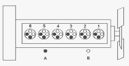
Cylinder and valve location - (A) Exhaust valve, (B) Inlet valve
If the valve lash requires adjustment several times in a short period of
time, excessive wear exists in a different part of the engine. Find the
problem and make necessary repairs in order to prevent more damage to
the engine. Not enough valve lash can be the cause of rapid wear of the
camshaft and valve lifters. Not enough valve lash can indicate that the
seats for the valves are worn. Valves become worn due to the following
causes: Fuel injection nozzles that operate incorrectly. Excessive dirt
and oil are present on the filters for the inlet air. The load capacity
of the engine is frequently exceeded.
Too much valve lash can cause broken valve stems, springs, and spring
retainers. This will produce emissions in excess of the correct
specification. Too much valve lash can be an indication of the following
problems: Worn camshaft and valve lifters, Worn rocker arms, Bent
pushrods, Broken socket on the upper end of a pushrod, Loose adjustment
screw for the valve lash. If the camshaft and valve lifters show rapid
wear, look for fuel in the lubrication oil or dirty lubrication oil as a
possible cause.
Valve Lash Check - An adjustment is NOT NECESSARY if the measurement of
the valve lash is in the acceptable range. Check the valve lash while
the engine is stopped. The temperature of the 1106 Perkins engines does
not change the valve lash setting. If the measurement is not within the
acceptable clearance, adjustment is necessary.
Valve Lash Adjustment - The No. 1 Cylinder is at the front of the 1106
Perkins diesel engine. When the engine is new, the valve lash should be
checked and reset after a service interval of 1000 hours. For example,
if the pushrods in a remanufactured engine have been replaced with new
parts then Adjust the valve lash to 0.25 ± 0.05 mm (0.0098 ± 0.0020
inch) for the initial rebuild. The tappets should be reset to 0.35 ±
0.05 mm (0.0138 ± 0.0020 inch) at the normal service intervals
thereafter.
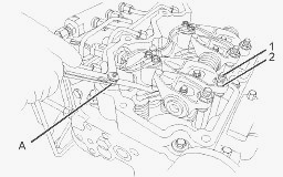
Setting the valve lash - (A) Angled feeler gauge (1) Adjustment screw
(2) Locking screw
Remove the valve mechanism cover. When the valve mechanism cover is
removed or installed, the electrical harness must be checked. Do not
trap the injector harness when the valve mechanism cover is installed.
Do not allow the harness to be in contact with the valve mechanism
cover. Renew the harness, if the harness is damaged.
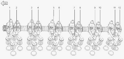
Rotate the crankshaft clockwise until the pair of inlet valves (11) is
fully open. Measure the valve lash on inlet valves (9) and exhaust
valves (10). If necessary, adjust the valve lash to the settings in
Table. Complete the sequence of checks according to Table until all the
cylinders have been checked or adjusted.
Loosen the valve adjustment screw locknut that is on the adjustment
screw (1). Place Tooling between the rocker arm and the valve. Turn the
adjustment screw (1) while the valve adjustment screw locknut (2) is
being held from turning. Adjust the valve lash until the correct
specification is achieved. After each adjustment, tighten the valve
adjustment screw locknut while you hold the valve adjustment screw (1)
from turning. Complete the sequence of checks according to Table until
all the cylinders have been checked or adjusted. Reinstall the valve
mechanism cover.
Valve Depth – Inspect
Ensure that the face of the valves are clean. Ensure that the bottom
face of the cylinder head is clean. Ensure that the cylinder head is not
distorted. Use the Tooling to check the depths of the inlet valves and
the exhaust valves below the face of the cylinder head. Measure the
depth of the inlet valve and the exhaust valve below the cylinder head
face.
The minimum and maximum limits for a new 1106 Perkins engines follow:
Inlet valves - Minimum - 1.40 mm (0.055 inch) / Maximum - 1.70 mm (0.067
inch)
Exhaust valves - Minimum - 1.50 mm (0.059 inch) / Maximum - 1.80 mm
(0.071 inch)
Service wear occurs on an engine which has been in operation. If the
valve depth below the cylinder head face on a used 1106 Perkins motor
exceeds the specification for service wear, the following components
must be replaced. Wear limit for inlet valves - 1.95 mm (0.077 inch).
Wear limit for exhaust valves - 2.05 mm (0.081 inch)
Check each valve for cracks. Check the stems of the valves for wear.
Ensure that the valves are the correct fit in the valve guides. Check
the load on the valve springs.
Valve Guide - Inspect
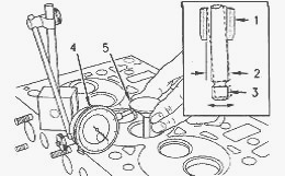
Measure the radial movement of the valve in the valve guide - (1) Valve
guide (2) Radial movement of the valve in the valve guide (3) Valve stem
(4) Dial indicator (5) Valve head
Place a new valve in the valve guide. Place a dial indicator with a
magnetic base on the face of the cylinder head. Lift the edge of the
valve head to a distance of 15.0 mm (0.60 inch). Move the valve in a
radial direction away from the dial indicator. Make sure that the valve
moves away from the dial indicator as far as possible. Position the
contact point of the dial indicator on the edge of the valve head. Set
the position of the needle of the dial indicator to zero.
Move the valve in a radial direction toward the dial indicator as far as
possible. Note the distance of movement which is indicated on the dial
indicator. If the distance is greater than the maximum clearance of the
valve in the valve guide, replace the valve guide. The maximum clearance
for the inlet valve stem in the valve guide with a valve lift of 15.0 mm
(0.60 inch) is the following value - 0.08 mm (0.0031 inch).
The maximum clearance for the exhaust valve stem in the valve guide with
a valve lift of 15.0 mm (0.60 inch) is the following value - 0.09 mm
(0.0035 inch). The original valve guides are bored into the cylinder
head. When new valve guides(1) are installed, new valves and new valve
seat inserts must be installed. The cylinder head must be rebored in
order to install the new valve guide. Valve guides and valve seat
inserts are supplied as an unfinished part. The unfinished valve guides
and unfinished valve seat inserts are installed in the cylinder head.
Then, the valve guides and valve inserts are cut and reamed in one
operation with special tooling.
________________________________________________________________________________
________________________________________________________________________________________
 SPECS
SPECS LOADERS
 MAINTENANCE
 PROBLEMS
________________________________________________________________________________________
 MF 1523
 MF 1531
 MF 135
 MF 1547
 MF 1635
________________________________________________________________________________________
________________________________________________________________________________________
 231
231 231S
231S 235
235 240
240 241
241________________________________________________________________________________________
 255
255 265
265 274
274 285
285 375
375________________________________________________________________________________________
________________________________________________________________________________________
 916X Loader
 921X Loader
 926X Loader
 931X Loader
 936X Loader
________________________________________________________________________________________
 941X Loader
 946X Loader
 951X Loader
 956X Loader
 988 Loader
________________________________________________________________________________________
 1655
1655 GS1705
 1742
1742 2635
2635 4608
4608________________________________________________________________________________________
 1080
1080 1100
1100 2615
2615 3050
3050 3060
3060________________________________________________________________________________________
 4708
4708 5455
5455 5450
5450 5610
5610 5613
5613________________________________________________________________________________________
 DL95 Loader
 DL100 Loader
 DL120 Loader
 DL125 Loader
 DL130 Loader
________________________________________________________________________________________
 DL135 Loader
 DL250 Loader
 DL260 Loader
 L90 Loader
 L100 Loader
________________________________________________________________________________________
 6499
6499 7480
7480 7618
7618 7726
7726 1533
1533________________________________________________________________________________________
 2604H
2604H 2607H
2607H 4455
4455 4610M
4610M 4710
4710________________________________________________________________________________________
 L105E Loader
 L210 Loader
 1014 Loader
 1016 Loader
 1462 Loader
________________________________________________________________________________________
 1525 Loader
 1530 Loader
 232 Loader
 838 Loader
 848 Loader
________________________________________________________________________________________
 5712SL
 6713
6713 6715S
6715S 7475
7475 7615
7615________________________________________________________________________________________
 7716
7716 7724
7724 8240
8240 8650
8650 8732
8732________________________________________________________________________________________
 246 Loader
 1036 Loader
 1038 Loader
 1080 Loader
 856 Loader