
________________________________________________________________________________
Removing and install the MF 6465, 6470, 6499, 6495 tractor right-hand hydraulic cover plate
Immobilise the tractor. Chock the left rear wheel.
If the Massey Ferguson 6465, 6470, 6499, 6495 tractor is not equipped
with a Park Lock device, engage the hand brake.
Chock between the frame and the front axle (optional).
Partially drain the intermediate housing (GPA30 rear axle) or the centre
housing (GPA20 and GPA40 rear axles).
Remove the rear right-hand wheel. Place a safety stand under the trumpet
housing. Mark and disconnect the pipes or hoses, the solenoid valve
harnesses (depending on version), switches and the engine speed sensor
connected to the hydraulic cover plate (8).
Remove the 60 μ filter (49) (GPA30, GPA40 rear axles).
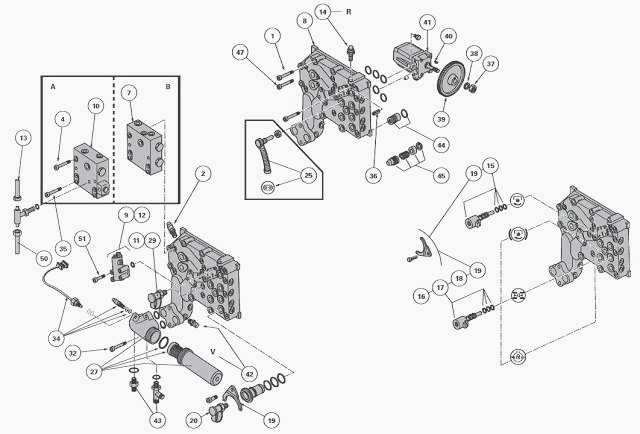
Unscrew:
- the screws (32). Remove the main filter assembly (27);
- the screws (4). Remove the single priority block (B) or the hydraulic
unit with two priority blocks (A+B).
In order to avoid draining the trailer brake system on MF 6465, 6470,
6499, 6495 tractors fitted with a two-priority block hydraulic unit, it
is recommended to remove the complete unit from the hydraulic cover
plate without disconnecting the control hose (22) from the brake master
cylinders (40 kph tractors) or from the block/valve
assembly (tractors fitted with high-pressure braking).
Unscrew the screws (1). Release and remove the hydraulic cover plate.
Remove the seal (4). Discard this seal.
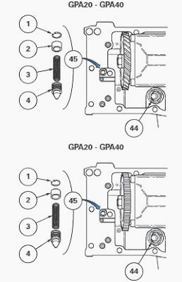
If necessary, remove the safety valve (45)
from the low pressure system by proceeding as follows:
- Compress the spring (3) using a screwdriver.
- Remove the circlip (1).
- Remove the components (2) to (4).
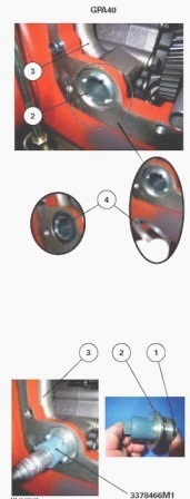
If necessary, unscrew the castellated collar (2) (GPA40) using pin
wrench 3378466M1. If necessary, discard and replace the "O" ring (1).

Reinstall
Clean the mating face of the intermediate housing (GPA30) or centre
housing (GPA20 and GPA40) and the mating face of the right-hand
hydraulic cover plate.
If necessary, screw on and tighten the castellated collar (2) using the
pin. If necessary, reinstall the safety valve (45).
Check that the component (4) slides freely in its housing after
reinstalling.
Check the Massey Ferguson 6470, 6465, 6499,
6495 hydraulic cover plate for presence of:
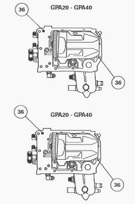
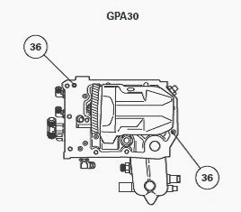
- the locating pins (36);
- the rivets obstructing the end of the hydraulic channels of the
hydraulic cover plate faces (external and internal).
For GPA30, if necessary:
- position the pipe of the 5 bar safety valve in the intermediate
housing by placing its end, Installed with a seal, in the Mecanindus
pin. This pin is located on partition C of the intermediate housing;
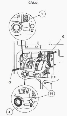
- Install the charge pipe (54) fitted with an "O" ring (52) in the
intermediate housing by placing the pipe notch in the pin (1).
Lightly smear the seal (4) with miscible
grease. Position this seal:
- on the collar of the pipe (54) (GPA30);
- on the castellated collar (2) screwed onto the pipe (3) (GPA40).
Lightly smear the mating face of the intermediate housing (GPA30) or
centre housing (GPA20 and GPA40) with a sealing product such as Loctite
5206 or equivalent.
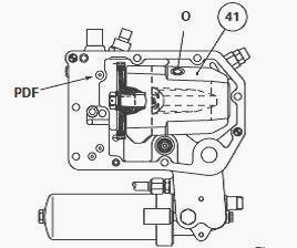
For the MF 6470, 6465, 6499, 6495 GPA20 and GPA40 rear axles, do not
obstruct the PTO hydraulic port.
If necessary, screw on two diametrically opposed guide studs (G) onto
the intermediate housing (GPA30) or centre housing (GPA20 and GPA40).
Fill the variable displacement pump (41) with clean transmission oil
through port O.
Slide the cover plate onto the guide studs (G) previously screwed onto
the intermediate housing (GPA30) or centre housing (GPA20 and GPA40).
Using a bronze hammer, gently tap the rim of the hydraulic cover plate
(8) to begin engagement of the locating pins (36) in the intermediate or
centre housing.
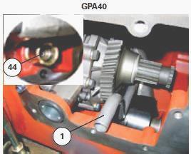
When fitting the hydraulic cover plate to the intermediate or centre
housing, check between the mating faces (cover plate and housing) to
ensure that the continuity pipe (1) (GPA20 and GPA40) or (55) (GPA30) is
correctly fitted in the 5 bar safety valve (44) as per the GPA40
example.
Screw in the screws (1) and simultaneously remove guide studs G (if
used). Tighten these screws to a torque of 120-160 Nm. If resistance is
felt during tightening, do not continue.
Move aside the hydraulic cover plate for the intermediate housing
(GPA30) or centre housing (GPA20 and GPA40) and check that the
continuity pipe or (55) is fitted in the 5 bar safety valve.
Also turn the driven gear (39) of the Massey Ferguson 6465, 6470, 6499,
6495 variable displacement pump to assist with gear engaging.

Replace the "O" rings (1) to (3) for the single priority block (7)
(tractors without trailer braking) or for the hydraulic unit with two
priority blocks [(7) and (10)] (tractors with trailer braking).
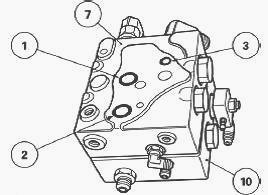
Reinstall the single priority block or the hydraulic unit with two
priority blocks (7) or [(7) and (10)]. Lightly smear the thread of the
screws with Loctite 542 or equivalent. Tighten these screws to a torque
of 25 - 35 Nm.
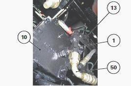
For MF 6465, 6470, 6499, 6495 tractors fitted
with a GPA30 rear axle and a trailer brake mechanism:
- Tighten the T connector (1) in the vertical position. Never replace
the T connector (1) with a standard plug.
- Tighten the hose (13).
- Temporarily tighten the hose (50) while awaiting the filling
operation.
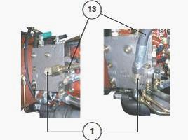
For Massey Ferguson 6499, 6470, 6465, 6495
tractors fitted with a GPA20 or GPA40 rear axle and a trailer brake
mechanism:
- Tighten the elbow union (1). Never replace the elbow union 1) with a
standard plug.
- Tighten the pipe or hose (13) (depending on version).
If necessary, adjust the engine speed sensor
located on the hydraulic cover plate. Reconnect:
- the switches;
- the solenoid valve harnesses;
- the pipes and hoses.
Top up the rear axle oil level. Check using the dipstick or the sight
glass (depending on version).
For MF 6499, 6470, 6465, 6495 tractors
equipped with a GPA30 rear axle and a trailer brake mechanism:
- Charge the hose (50) for the priority block (10).
- Definitively tighten the hose (50).
If the variable displacement pump had to be replaced, perform the
hydraulic tests. Lift the right-hand side of the tractor rear axle.
Reinstall the wheel. Remove the axle stand. Tighten the wheel nuts.
Check for correct operation:
- of the electrical and electronic circuits;
- of the switches;
- of the solenoid valves.
Carry out a road test.
Check tightness of:
- the right-hand hydraulic cover plate;
- the mating faces;
- Hydraulic unions
________________________________________________________________________________
________________________________________________________________________________________
 SPECS
SPECS LOADERS
 MAINTENANCE
 PROBLEMS
________________________________________________________________________________________
 MF 1523
 MF 1531
 MF 135
 MF 1547
 MF 1635
________________________________________________________________________________________
________________________________________________________________________________________
 231
231 231S
231S 235
235 240
240 241
241________________________________________________________________________________________
 255
255 265
265 274
274 285
285 375
375________________________________________________________________________________________
________________________________________________________________________________________
 916X Loader
 921X Loader
 926X Loader
 931X Loader
 936X Loader
________________________________________________________________________________________
 941X Loader
 946X Loader
 951X Loader
 956X Loader
 988 Loader
________________________________________________________________________________________
 1655
1655 GS1705
 1742
1742 2635
2635 4608
4608________________________________________________________________________________________
 1080
1080 1100
1100 2615
2615 3050
3050 3060
3060________________________________________________________________________________________
 4708
4708 5455
5455 5450
5450 5610
5610 5613
5613________________________________________________________________________________________
 DL95 Loader
 DL100 Loader
 DL120 Loader
 DL125 Loader
 DL130 Loader
________________________________________________________________________________________
 DL135 Loader
 DL250 Loader
 DL260 Loader
 L90 Loader
 L100 Loader
________________________________________________________________________________________
 6499
6499 7480
7480 7618
7618 7726
7726 1533
1533________________________________________________________________________________________
 2604H
2604H 2607H
2607H 4455
4455 4610M
4610M 4710
4710________________________________________________________________________________________
 L105E Loader
 L210 Loader
 1014 Loader
 1016 Loader
 1462 Loader
________________________________________________________________________________________
 1525 Loader
 1530 Loader
 232 Loader
 838 Loader
 848 Loader
________________________________________________________________________________________
 5712SL
 6713
6713 6715S
6715S 7475
7475 7615
7615________________________________________________________________________________________
 7716
7716 7724
7724 8240
8240 8650
8650 8732
8732________________________________________________________________________________________
 246 Loader
 1036 Loader
 1038 Loader
 1080 Loader
 856 Loader