________________________________________________________________________________
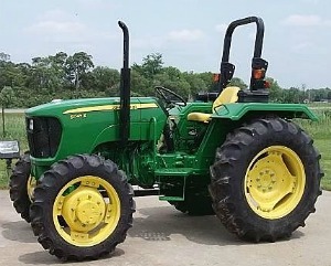
John Deere 2520 Attachments
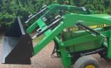
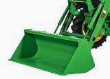
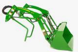
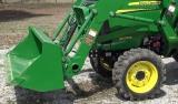
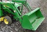
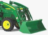
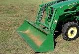
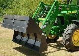
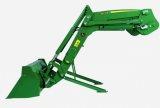
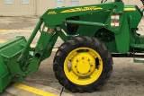
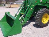
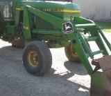
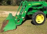
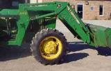
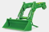
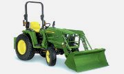
John Deere 2520 Front End Loader
200CX Loader Specifications
Type of Attachment - Front End Loader
Compatibility - John Deere 2520
Height (to pin) - 89.5 in. (227 cm)
Clearance, dumped bucket - 58.5 in. (148 cm)
Dump reach - 29.5 in. (74 cm)
Dump angle - 38
Reach at ground - 50.3 in. (127 cm)
Rollback at ground - 25
Rollback, raised - 105
Breakout force (at pin) - 2239 lb (1015 kg)
Breakout force (at 500 mm) - 1515 lb (687 kg)
Breakout force (bucket) - 1702 lb (772 kg)
Lift to full height (at pin) - 902 lb (409 kg)
Lift to full height (at 500 mm) - 629 lb (285 kg)
Lift to 1.5m (at pin) - 1124 lb (509 kg)
Lift to 1.5m (at 500 mm) - 827 lb (375 kg)
200CX Loader Bucket width - 53 in. (134 cm)
Raise time to height - 3.19 sec
Bucket dump time - 3.19 sec
Lowering time - 1.95 sec
Rollback time - 1.95 sec
200X Loader Specifications
Type of Attachment - Front End Loader
Compatibility - John Deere 2520
Lifting capacity at pivot pin (maximum height) - 800 lb. (363 kg)
Lifting capacity at 0.5 m ahead of pivot pin - 557 lb. (253 kg)
Lifting capacity to 59 in. at pivot pin - 1031 lb. (465 kg)
Lifting capacity to 59 in. at 0.5 m ahead - 758 lb. (344 kg)
Maximum Lifting height at pivot pin - 78.7 in. (1,99 m)
Reach at maximum height - 29.2 in. (0,75 m)
Breakout force at pivot pin - 2137 lbf. (9505N)
Dump angle - 38 degrees
Rollback angle - 25 degrees
Loader raising/lowering time - 3,19/1,95 sec.
Bucket dump time/regen - 3,19/1,25 sec.
Bucket rollback time - 1,95 sec.
Bucket Level Indicator
- Cleaning concrete surfaces causes rapid bucket wear. Bucket level
indicator helps to ensure bucket rides on wear pads. Adjusting Bucket
Level Indicator: Loosen cap screw. Adjust rod up or down until bend
rests in guide bracket. Tighten cap screw to hold rod securely in place.
O-Ring Installation
- Inspect groove and/or seat. Flat face O-ring seal: Apply petroleum
jelly to O-ring and place in groove. O-ring boss: Install O-ring
carefully over threads. Install fittings by hand until snug, position
adjustable fittings by unscrewing no more than one turn.
Replacing Orifice -
Orifice must be in place for more efficient use of JD 2520 tractor
hydraulics. The lift circuit orifice slows the lowering and improves
control of lift arms. Orifice, is in the head-end lift cylinder fitting
with cap color-coded blue. Flat face of orifice must be against inside
of adapter fitting. Tighten according to specifications.
Assembly Sequence -
Prepare the tractor. Install mounting frames. Install hood guard.
Prepare the 200X loader. Install bucket/attachment. Install hydraulic
hoses. Position loader to mount on tractor. Attach loader to tractor.
Perform final inspection and adjustments. Install optional
equipment/attachments.
John Deere 2520 Backhoe
46 Backhoe Specifications
Type of Attachment - Backhoe
Compatibility - John Deere 2520
Digging depth - 198 cm (6 ft 6 in)
Loading height (bucket at 60 degrees) - 150 cm (5 ft)
Reach from center line of swing pivot - 257 cm (8 ft 5 in)
Transport height - 150 cm (5 ft)
Loading reach (bucket at 60 degrees) - 97 cm (3 ft 2 in)
Transport overhang - 104 cm (3 ft 5 in)
Undercut - 71 cm (2 ft 4 in)
Swing arc - 180 degrees
Weight - 896 lbs (407 kg)
Bucket Rotation - 180 degrees
Stabilizers spread width, up - 119 cm (3 ft 11 in)
Stabilizers spread width, down - 198 cm (6 ft 6 in)
Boom lift capacity - 348 lbs (158 kg)
Dipperstick digging force - 1250 lbs (5560 N)
Bucket digging force - 2450 lbs (10900 N)
Bucket control main relief valve pressure - 2250 psi (15510 kPa)
Preparing JD 2520 Tractor and
Install Front Loader - Park JD 2520 tractor safely. If
installed, remove mid-mount mower deck. Remove 3-point hitch and drawbar
hitch: Remove locking pins and center link. Remove strap. Remove locking
pin and remove drawbar. Remove locking pins from lift links and lower
the lift links. Remove locking pins from draft link pins. Slide draft
link pins in. Remove sway links, draft links, and lift links.
Disassemble links as needed and install locking pins in links for
storage. Remove eight bolts from drawbar hitch and remove drawbar hitch.
Remove and retain draft links pins with locking pins from drawbar hitch.
Remove four bolts from three piece PTO shield and remove shield from
drawbar hitch. Install rear mounting support: Install draft link pins in
rear mounting support, and install rear mounting support with eight
M12x1.75 cap screws and 1/2 in. lockwashers. Tighten to 113 Nm (83
lb-ft).
Install draft link pins in drive housings and install locking pins in
draft link pins. Install three piece PTO shield on rear mounting support
with four new 1/4x3/4 in. bolts, eight 0.344x0.688 zinc plate washers,
and four 1/4 in. locknuts. Tighten to 12 Nm (106 lb-in.) Install
hangers: Loosely install hangers on loader mounts on both sides of
tractor with four U-bolts, eight 3/8x7/8 in. washers and locknuts.
Position hangers centered on tractor with 22 in. space between inside
surfaces of outer lugs. Align 46 backhoe subframe: Use proper lifting
device to position and install subframe hooks onto draft link pins. Push
down to pivot subframe rear end and align holes on subframe front end
with holes in hangers. Position hangers as needed for subframe
alignment. Tighten locknuts on hanger U-bolts to 47 Nm (35 lb-ft). Use
proper lifting device to remove subframe from draft link pins. Inflate
tires to maximum pressure recommended by tire manufacturer. Install Tall
Folding Roll Over Protection System (ROPS). Install Power Beyond kit.
Follow tractor operator’s manual instructions to check hydraulic fluid
level.
John Deere 2520 Mower Deck
72 inch Mower Specifications
Model - 272 Side Discharge Grooming Mower
Mower Type - Rear-Mounted
Cutting Width - 72 in. (1.8 m)
Cutting Height (Adjustable) - 2 to 5 in. (51 to 127 mm)
Overall Width - 85 in. (2.16 m)
Overall Length - 53.1 in. (1.35 m)
Overall Height - 39.4 in. (1.0 m)
Blades - 3 Heat-Treated Alloy Steel - 2.5x24.9x.312 in. (63.5 x 634 x
7.9 mm)
Deck - One-piece stamped steel, 5/32 in. (4 mm)
Spindles - Greaseable from top
Gauge Wheels - Rear, semi-pneumatic, adjustable
Mower Drive - 540-rpm rear PTO through right-angle gearbox to B-section
or C-section drive belt
Mower Lift - Through tractor’s rockshaft control
Net Weight - 510 Ib. (232 kg)
Attachment - Front-gauge-wheel kit
62-inch Mower Deck Specifications
Model - 62D OnRamp Mid-Mount Mower Deck
Mower Type - Mid-Mount
Compatibility - JD 2520
Cutting Width - 62 in. (1570 mm)
Overall Width, Defl ector Up - 69 in. (1750 mm)
Overall Width, Defl ector Down - 72.5 in. (1840 mm)
Cutting Height - 1-5 1/4 in. (25-133 mm)
Number of Spindles/Blades - 3
Spindle Drive - V-belt
Blade Orientation - Staggered, overlapping
Standard Blades - Medium lift
Deck Thickness - 3.4 mm (10 ga.)
Mower Wheels - 4
Wheel Adjustment - Quick-release
Front Rollers - Yes
Memory Setting for Mower Wheels - Yes
Mulching - Opt.
Power Flow Blower - Opt.
14-Bushel Rear Hopper - Opt.
Weight - 497 lb.
Adjusting Upstop Clearance
- Fully raise the 62D mower. Park machine safely. Check to be sure the
upstop is at least 2mm (1/16 in.) from contact with underside of John
Deere 2520 tractor. If upstop comes into contact with tractor, adjust
mower levels side-to-side and front-to-rear and adjust the lift links.
Service Intervals -
Every 10 Hours - If operating in dry conditions, clean debris from
mower. Every 25 Hours - Lubricate spindles, driveshaft, wheels, mower
lift kit. Inspect mower blades and belt. Every 100 Hours - Check gearbox
oil level. Wash mower. Inspect rollers. Every 500 Hours - Change gearbox
oil.
72-inch Mower Deck Specifications
Model - 72" Mid-Mount Mower Deck
Width of Cut - 72.8 in. (1849 mm)
Width - 85 in. (2159 mm)
Length - 41.7 in. (1060 mm)
Height - 17.1 in. (435 mm)
Minimum Cutting Height - 1 in. (25 mm)
Blades - 3
Gauge Wheels - Polyolefin
Spindles - 1.00 in. (25.4 mm)
Net Weight - 331 Ib. (150 kg)
John Deere 2520 Snowblower
54 Inch Quick-Hitch Snowblower Specifications
Type - Front Mount
Compatibility - JD 2520
Clearing Width - 1.40 m (54 in.)
Height to Top of Spout - 78 cm (30-5/8 in.)
Length - 69 cm (27 in.)
Lift Height - 279 mm (11 in.)
Net Weight - 113 kg (250 lb.)
Scraper Blade Reversible and Replaceable - 1.3 m (59-15/16 in.)
Discharge Chute Control - Hydraulic
Discharge Chute Rotation - 100° to each side
Snowblower Drive - Splined coupler shaft to gear case
Snowblower Lift - Hydraulic
Rotor Length - 1 m (39-3/8 in.)
Auger Speed - 176 rpm
Auger Diameter - 40.6 cm (16 in.)
Impeller Speed - 950 rpm
Impeller Diameter - 40.3 cm (15.5 in.)
Drive - Gear case to roller chain
Bearings - Sealed ball bearings
Operating Attachment
- Install appropriate tire chains to improve traction. Required Ballast:
Two wheel weights. Recommended ballast: Rear weight box with 9 suit case
weights (with this option wheel weights not needed). To improve
traction: Certain working conditions may be improved by using tire
chains or rear ballast. Install chains on rear drive tires. Install
wheel weights on rear drive wheels. Install rear weight bracket or rear
weight box with suitcase weights. Move the machine to an outside area
before running the engine.
Connect a pipe extension to the engine exhaust pipe to direct the
exhaust fumes out of the area. Start engine. Push lever forward
completely to lower attachment to ground and lock in float position. Do
not engage PTO with throttle in the fast position. Engage PTO. Operate
attachment at full throttle position for best performance. Move throttle
lever to full throttle position. To improve traction and steering,
engage differential lock or engage four-wheel drive, if equipped. Push
down on forward foot control pedal to begin forward movement.
John Deere 2520 Front Blade
54-inch Front Blade Specifications
Compatibility - JD 2520
Cutting Width, Blade Straight - 54-in. (1.4 m)
Cutting Width, Blade Angled 15 Degrees - 52-3/16-in. (1.3 m)
Cutting Width, Blade Angled 27 Degrees - 48-in. (1.2 m)
Angling Positions (Right and Left) - 0 to 27 degrees Approx.
Blade Material - 11-gauge steel
Blade Trip - Spring trip
Blade Float - Hydraulic
Blade Skid Shoes - 8 position
Range of Lift (Above Ground Line) - 11-in. (280 mm)
Range of Lift (Below Ground Line) - 3-1/2-in. (90 mm)
Weight - 50 lb. (23 kg)
John Deere 2520 Rotary Tiller
RT1157 Rotary Tiller Specifications
Model - Frontier RT1157 Rotary Tiller
Working width - 57 inch (1.45 m)
Tractor hp (minimum-maximum) - 25-40 hp (19-30 kW)
Depth control - Adjustable skid shoes
Weight with skid shoes - 480 lb. (218 kg)
Gearbox speed - Single
Side drive - Chain ASA 80
Tractor PTO speed - 540 rpm
Hitch compatibility - Category 1 iMatch
Offset - 15.5 in. (393.7 mm)
Maximum working depth - 7 in. (178 mm)
Blade type - C
Blade per flange - 6
Rotor flanges - 7
Rear door support - Chain
Installing Frontier RT1157 tiller on
2520 tractor - Back tractor into position and align
draft links with draft link brackets on tiller using tractor rockshaft
control. Fasten each draft link to draft link brackets with drilled pins
and quiklock pins. Locate driller pin in top holes. Install center link
on tiller and fasten with drilled pin and quiklock pin. Install PTO
shaft to tractor. Engage the cardan shaft and check that it is perfectly
locked on the tractor PTO. Check that the guard is free to turn and fix
it with the relative latch. Raise tiller. Remove spring locking pin from
parking stand. Slide parking stand all the way up on tiller bracket.
Fasten with spring locking pin. Level tiller. Adjust sway chains on
tractor lower draft arms to minimize side way.
PTO shaft with clutch
- The PTO shaft can be equipped with safety clutch to protect the
transmission components of the machine from stress and/or excessive
overloads. The tilt of the PTO shaft must not exceed 10 degrees. The
clutch is already pre-adjusted for average stress. If it slips too
easily (and overheats), it will be necessary to evenly tighten all the
nuts that retain the spring. The clutch disks must be changed if the
clutch still slips after all the nuts have been tightened. If the clutch
does not slip, evenly unscrew all the spring fixing nuts. Unscrew one
turn at a time and check the clutch after having worked about 300
meters. Repeat the operation if necessary, remembering to unscrew one
turn at a time. If the clutch maintains a temperature of about 40-50C
(104-122F) degrees during work, this means that it has been correctly
regulated.
________________________________________________________________________________
________________________________________________________________________________________
 JD SPECS
 JD LOADERS
 JD MAINTENANCE
 JD INSTRUCTIONS
 JD PROBLEMS
________________________________________________________________________________________
 JD 2025R
 JD 3039R
 JD 4044R
 JD 4105
 JD 4720
________________________________________________________________________________________
 420 Loader
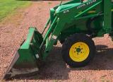 419 Loader
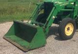 510 Loader
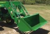 512 Loader
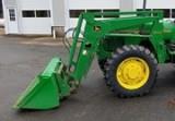 520 Loader
________________________________________________________________________________________
 520M Loader
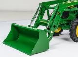 540M NSL
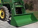 540 Loader
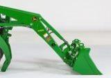 440R Loader
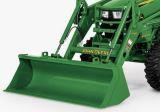 H180 Loader
________________________________________________________________________________________
________________________________________________________________________________________
 JD 5045E
 JD 5085E
 JD 5100M
 JD 6105R
 JD 6120M
________________________________________________________________________________________
 JD 6155M
 JD 6195R
 JD 6210R
 JD 7210R
 JD 7250R
________________________________________________________________________________________
 JD 7310R
 JD 8245R
 JD 8295R
 JD 8370R
 JD 9370R
________________________________________________________________________________________
 120R Loader
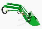 D120 Loader
 H120 Loader
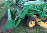 45 Loader
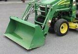 200CX Loader
________________________________________________________________________________________
 D160 Loader
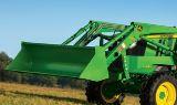 D170 Loader
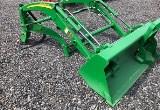 H160 Loader
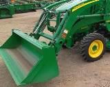 H165 Loader
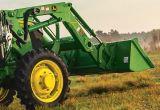 H240 Loader
________________________________________________________________________________________
 210 Loader
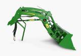 220R Loader
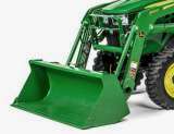 300E Loader
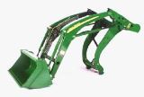 300X Loader
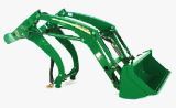 300CX Loader
________________________________________________________________________________________
 JD 9420R
 JD 9510R
 JD GX335
 JD GX85
 JD LA105
________________________________________________________________________________________
 JD 5065M
 JD 5055D
 JD 5115R
 JD 5105M
 JD 6110R
________________________________________________________________________________________
 JD 6130D
 JD 6225
 JD 7530
 JD 4044M
 JD 7185J
________________________________________________________________________________________
 300 Loader
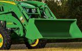 300R Loader
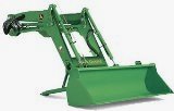 320R Loader
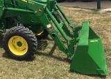 400E Loader
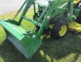 410 Loader
________________________________________________________________________________________
 430 Loader
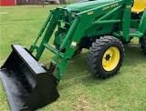 460 Loader
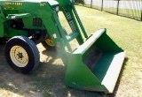 521 Loader
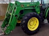 531 Loader
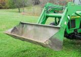 541 Loader
________________________________________________________________________________________
 551 Loader
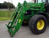 631 Loader
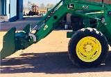 651 Loader
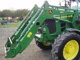 661 Loader
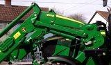 603R Loader
________________________________________________________________________________________
 JD D130
 JD D160
 JD 325
 JD 335
 JD 345
________________________________________________________________________________________
 JD 2520
 JD 3005
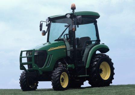 JD 3720
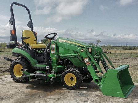 JD 1025R
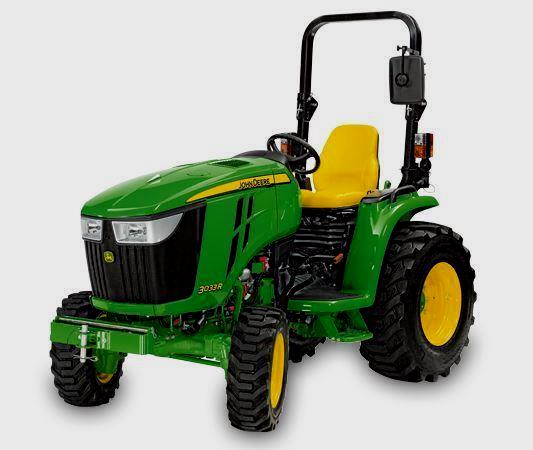 JD 3033R
________________________________________________________________________________________
 JD 5090EL
 JD 5100MH
 JD 5075GV
 JD 6090RC
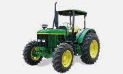 JD 6110B
________________________________________________________________________________________
 623R Loader
 643R Loader
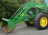 731 Loader
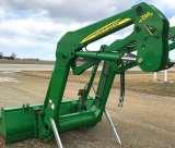 746 Loader
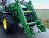 751 Loader
________________________________________________________________________________________
 533 Loader
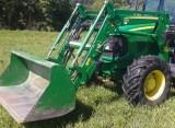 583 Loader
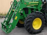 633 Loader
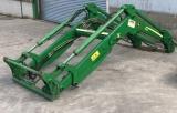 653 Loader
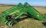 683 Loader
________________________________________________________________________________________
 H260 Loader
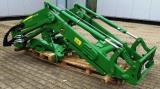 663R Loader
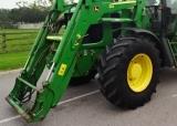 663 Loader
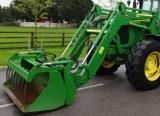 683R Loader
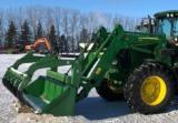 753 Loader
________________________________________________________________________________________
 JD 6125J
 JD 6150RH
 JD 6210J
 JD 7195J
 JD 8310
________________________________________________________________________________________
 JD 6325
 JD 5525
 JD 5083EN
 JD 5100GN
 JD 5125R
________________________________________________________________________________________
 210C Backhoe
 300D Backhoe
 310G Backhoe
 410G Backhoe
 710G Backhoe
________________________________________________________________________________________
 80 Loader
 100 Loader
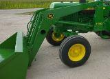 146 Loader
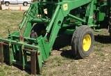 148 Loader
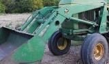 158 Loader
________________________________________________________________________________________
 168 Loader
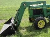 175 Loader
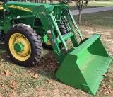 522 Loader
 542 Loader
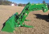 540R Loader
________________________________________________________________________________________
 562 Loader
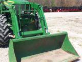 563 Loader
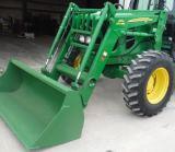 673 Loader
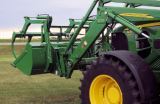 741 Loader
________________________________________________________________________________________
 L108 Automatic
 L120 Automatic
 LA110 Automatic
 LA120 Automatic
 LA150 Automatic
________________________________________________________________________________________
 LT155
LT155 LT160 Automatic
 LT180 Automatic
 LTR180
 X165
X165________________________________________________________________________________________
 E100
E100 E120
E120 E150
E150 LTR166
________________________________________________________________________________________
 LA135
LA135 LA165
LA165 LX277
LX277 LX288
LX288 LX255
LX255________________________________________________________________________________________
 S240
S240 GT235
GT235 G110 Automatic
 JD 3203
 JD 5520
________________________________________________________________________________________
 JD 316
 JD 420
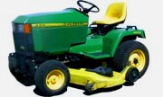 JD 425
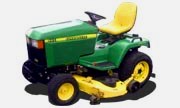 JD 445
________________________________________________________________________________________
 JD_5050D
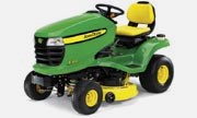 X300
X300 X304
X304 X310
X310 X110 Automatic
________________________________________________________________________________________
 H310 Loader
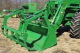 H340 Loader
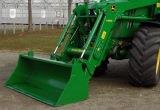 H360 Loader
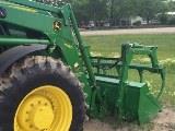 H380 Loader
 H480 Loader
________________________________________________________________________________________
 240 Loader
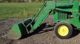 245 Loader
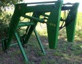 260 Loader
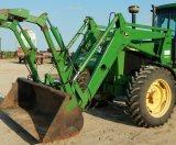 265 Loader
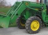 280 Loader
________________________________________________________________________________________
 600R Loader
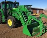 620R Loader
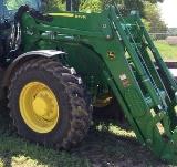 640R Loader
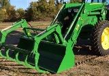 660R Loader
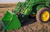 680R Loader
________________________________________________________________________________________
 JD_5039D
 X146R
X146R X360
X360 X155R
X155R X140 Automatic
________________________________________________________________________________________
 X350
X350 X380
X380 X500
X500 X590
X590 X700
X700________________________________________________________________________________________
 3036E
3036E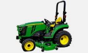 2038R
2038R 3038R
3038R 4049M
4049M JD 4100
________________________________________________________________________________________
 X738
X738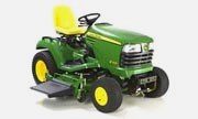 X740
X740 X748
X748 X749
X749 X950R
X950R________________________________________________________________________________________
 JD 4510
 5045D
5045D 5050E
5050E 5060E
5060E 5078E
5078E