________________________________________________________________________________
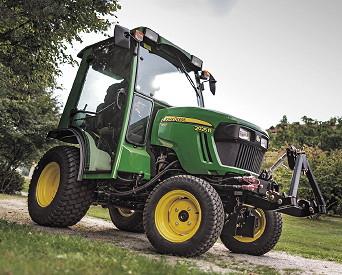
John Deere 3120, 3320, 3520, 3720 - Hydraulic and Hitch
John Deere 3120, 3320, 3520, 3720 Three Point Hitch
Drawbar Hitch
Maximum static vertical load on drawbar should not exceed the maximum recommendations. Drive slowly with heavy loads. Maximum Drawbar Loads - Certain heavy equipment such as a loaded single-axle trailer can place excessive strain on the drawbar. Strain is greatly increased by speed and rough ground. Adjusting Drawbar Length - For drawn PTO-driven implements, the drawbar must be in the operating position. The JD 3120, 3320, 3520, 3720 drawbar is equipped with two adjusting holes for changing drawbar length and one hole for storage. Remove quick-lock pin and drilled pin. Adjust drawbar to operating position, or to storage position. Install drilled pin up from bottom of machine. Secure with quick-lock pin.
3 Point Hitch
The 3-point hitch on John Deere 3120, 3320, 3520,
3720 tractor is classified as
a Category 1 hitch. Place center link in storage hook when the
hitch is not in use. Positioning Center Link - For light and medium
draft loads: Install center link in bottom hole of mounting
bracket. Example of light and medium draft load implements would include
a landscape rake. For medium and heavy draft loads: Install center link
in middle hole of mounting bracket. Example of medium and heavy
draft load implements would include a tiller or box blade. For very
heavy draft loads: Install center link in top hole of mounting
bracket. Example of very heavy draft load implements would include a
plow or ripper.
Using Rockshaft Control Lever
Use rockshaft control lever to raise and
lower equipment attached to the 3-point hitch. The six calibrated
setting are for reference only and do not signify specific operating
depths. When the rockshaft control lever is moved forward, the draft
arms will lower closer to the ground. Lower Implement: Push rockshaft
control lever forward. Raise Implement: Pull rockshaft control lever
rearward. The adjustable depth stop can be adjusted to maintain a
particular implement operating depth. To use the depth stop knob:
Operate implement for a few minutes to determine the desired operating
depth. Loosen the depth stop knob. Move knob against rockshaft control
lever. Tighten knob to keep the depth stop in position. Implement will
operate in same position each time rockshaft control lever is pushed
against the depth stop.
Using Rate of Drop/Lock Valve
To prevent overheating hydraulic oil and
damaging machine, do not raise rockshaft when drop/lock valve is closed.
The rate of drop/lock valve controls the rate of rockshaft drop when the
rockshaft control lever is operated. This provides direct rate of drop
control for 3-point hitch mounted implements. The valve can also be used
to hydraulically lock the rockshaft (three-point hitch) in a desired
position. Increase Rate of Drop: Rotate drop/lock valve knob
counter-clockwise to make drop faster. Decrease Rate of Drop: Rotate
drop/lock valve knob clockwise to make drop slower. Loss of hydraulic
pressure could result in sudden drop of attachment. Lower attachment
onto blocks or remove from machine before servicing. Lock 3-Point Hitch:
Rotate drop/lock valve knob clockwise until tight. Unlock 3-Point Hitch:
Rotate drop/lock valve knob counter-clockwise.
Using Draft Links
Slowly back machine into position to align draft
links with implement lift brackets. Park machine safely. For John Deere
3120, 3320, 3520, 3720 tractor
equipped with optional telescoping draft links: Raise locking lever and pull link to extend as needed. Connect draft links to the
implement. Telescoping draft link locking levers must be in locked
position before operating the machine or link damage could occur. For
machines equipped with optional telescoping draft links: Sit on
operator’s seat and start engine. Back machine until each lock lever
snaps and secures each draft link in the locked position.
John Deere 3120, 3320, 3520, 3720 Implements
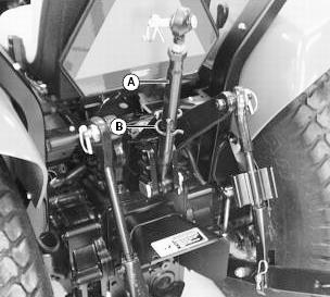
Leveling Implement Front-to-Rear
Leveling a 3-point hitch mounted
implement front-to-rear is accomplished by adjusting the length of the
center link. Loosen locknut. Do not turn center link body past the
stops, or threads may be damaged. Rotate handle to lengthen or
shorten the center link. Tighten locknut. Leveling Implement
Side-to-Side - Use turn handle on the right adjustable lift link to level a 3-point hitch implement side-to-side. Raise lift link turn
handle from transport position and locking tab. Rotate handle
approximately 1/2 turn. Lower handle notch onto roll pin. Rotate
handle to raise or lower draft link until 3-point hitch mounted
implement is level from side-to-side. Return handle to the transport
position with handle notch on locking tab.
Adjusting Implement Side-to-Side Sway
Check implement operator’s
manual procedure for adjusting sway links. When sway links have been
properly adjusted, side sway of implement is controlled by position of
links. Use left and right sway links to adjust 3-point hitch
implement side-to-side sway. Remove locking pin. Slide links to
adjust length. Install locking pin. Adjusting Draft Links to Float
Position - Adjusting 3-point hitch stops to the float position will
allow both draft links to raise slightly as the implement follows ground
contour. Adjust stops to the float position for 3-point hitch implements
such as a cultivator or mower. These implements will have ground gauging
skids or wheels which may otherwise cause the implement to twist
relative to the machine. Carefully remove spring locking pin,
drilled pin and stop connecting each draft link and lift link.
Connect each lift link and draft link with the same hardware, making
sure the stop is installed in the same position shown.
Adjusting Draft Links to Rigid Position
Adjusting 3-point hitch stops
to the rigid position will restrict movement of the draft links as the
implement follows ground contour. Adjust stops to the rigid position for
3-point hitch implements such as plows and ground engaging implements
that should not twist relative to the machine. Carefully remove spring
locking pin, drilled pin and stop connecting each draft link
and lift link. Connect each lift link and draft link with the same
hardware, making sure the stop is installed in the same position.
John Deere 3120, 3320, 3520, 3720 Tractor iMatch Quick-Hitch
John Deere 3120, 3320, 3520, 3720 tractor
Installing Hitch - Remove three drilled pins and two bushings from hitch. Use machine rockshaft control lever to fully lower 3-point
hitch draft links. Park machine safely. Position hitch near draft links
and adjust 3-point hitch sway links to align draft links with hitch.
Install hitch on draft links using drilled pins. Install 3-point hitch
center link on hitch using center link quick-lock pin and drilled pin.
Connecting Implement - Install two bushings included with hitch on
drilled pins in implement draft link lift brackets. Move levers on
hitch to unlocked position. Back machine into position and align hitch
with implement lift brackets. Use rockshaft control lever to position
hitch under lift brackets and lift implement from ground. Fully raise
implement. Move levers on hitch to locked position.
John Deere 3120, 3320, 3520, 3720 Tractor - Removing Implement and Hitch
With implement in raised position, move
levers to unlocked position, then lower implement to ground. Move
tractor forward to disengage hitch from implement. Move levers on hitch
to locked position. Use machine rockshaft control lever to fully lower
hitch and 3-point draft links. Remove drilled pins from 3-point hitch
center link and draft links. Place drilled pins in hitch for storage.
Move John Deere 3120, 3320, 3520, 3720 tractor forward to disengage from
hitch. Connecting Implement Hydraulic Hoses - Relieve hydraulic
pressure: Move dual selective control valve (SCV) lever
rearward-to-forward and side-to-side several times. Move third SCV lever
rearward-to-forward several times if equipped. See your implement
operator’s manual for specific instructions on connecting hydraulic
hoses to couplers. Install hose ends in couplers with matching colors.
Colors for the couplers are shown on the label installed on the machine
near the couplers. See your implement operator’s manual for specific
instructions on operating SCV controls. To prevent contamination of
female quick couplers, color-coded hose ends should be installed in the
couplers when not being used.
Dual Selective Control Valve Lever
The label installed on the machine next to the dual selective control valve (SCV) lever shows the different lever positions. Lever positions numbered 1-4 on the label match hydraulic line couplers numbered 1-4 on the label installed on the machine near the couplers. Moving the lever to position 1 will supply fluid to coupler 1 and return fluid through coupler 2 and so forth. Move the lever to the full right or regen position for faster loader bucket dumping. Move the lever to the full forward or float position to remove pressure in both lines 3 and 4 and allow fluid to flow back and forth between the lines. The lever may be left in the float position.
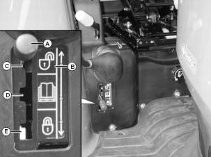
Dual Selective Control Valve (SCV) Lock
Lever
John Deere 3120,
3320, 3520, 3720 Tractor without Cab - Selective Control Valve (SCV)
lock lever allows the operator to control the type of dual SCV lever
movement needed for a particular operation or situation. Operation of
the lock lever is indicated on label. To allow movement of dual SCV
lever in all directions, move lock lever to the top position.
Operation of the dual SCV is totally unlocked. To prohibit engagement of
the regen (regeneration) function of the dual SCV, move lock lever to
the middle position. This position is recommended for all implements
except for the front loader. Heavily-loaded loader buckets will dump
more rapidly when the regen function is engaged. The regen function is
available only with the lock lever in position C. To prohibit movement
of dual SCV lever in all directions, move lock lever to the bottom
position. Operation of the dual SCV is totally locked.
JD 3120, 3320, 3520, 3720 Tractor with Cab - Selective Control Valve
(SCV) lock lever allows the operator to control the type of dual SCV
lever movement needed for a particular operation or situation. Operation
of the lock lever is indicated on label. To allow movement of dual
SCV lever in all directions, push the lock lever inward to center
position. Operation of the dual SCV is totally unlocked. To prohibit
engagement of the regen (regeneration) function of the dual SCV, push
the lock lever all the way inward. This position is recommended for
all implements except for the front loader. Heavily-loaded loader
buckets will dump more rapidly when the regen function is engaged. To
prohibit movement of dual SCV lever in all directions, make sure SCV
lever is in center position, and pull the lock lever straight
outward. Operation of the dual SCV is totally locked. After extended
use, the dual SCV lever may require cable adjustment to lock out.
Hydraulic Third Selective Control Valve (SCV)
John Deere 3120, 3320, 3520, 3720 tractor can be equipped with an optional hydraulic third Selective
Control Valve (SCV) and hydraulic outlets to operate
hydraulically-driven implements. The machine-mounted hydraulic outlets
are female quick couplers (A). When the implement hydraulic hoses are
connected to the couplers, move the third SCV lever forward to divert
fluid to the lower connector line and return through the upper connector
line. Move the lever rearward to divert fluid to the upper connector
line and return through the lower connector line. Move the lever to the
full forward or float position to remove pressure in both connector
lines and allow fluid to flow back and forth between the lines. See your
implement Operator’s Manual for implement functions which correspond to
lever positions. To prevent contamination of female quick couplers,
color-coded hose ends should be installed in the couplers when not being
used.
John Deere 3120, 3320, 3520, 3720 Diverter Valve
JD 3120, 3320, 3520, 3720 models can be equipped
with an optional diverter valve and hydraulic outlets to operate
hydraulically-driven implements. The machine-mounted hydraulic outlets
are female quick couplers. If the key switch is moved to the off
position, the dual SCV lever will default to operating the front quick
couplers. The key switch must be moved to the run position and the
diverter system re-activated to operate the rear couplers. Press the
front of the diverter switch to activate the rear SCV quick coupler
ports. The switch indicator light will go on. Press the back of the
diverter switch to deactivate the rear SCV quick coupler ports. The
switch indicator light will go off.
- JD 3120, 3320, 3520, 3720 Engine
- JD 3120, 3320, 3520, 3720 Transmission
- JD 3120, 3320, 3520, 3720 PTO
- JD 3120, 3320, 3520, 3720 Brakes and Wheels
- JD 3120, 3320, 3520, 3720 Hydraulic and Hitch
- JD 3120, 3320, 3520, 3720 Operating
- JD 3120, 3320, 3520, 3720 Troubleshooting
________________________________________________________________________________
________________________________________________________________________________________
 JD SPECS
 JD LOADERS
 JD MAINTENANCE
 JD INSTRUCTIONS
 JD PROBLEMS
________________________________________________________________________________________
 JD 2025R
 JD 3039R
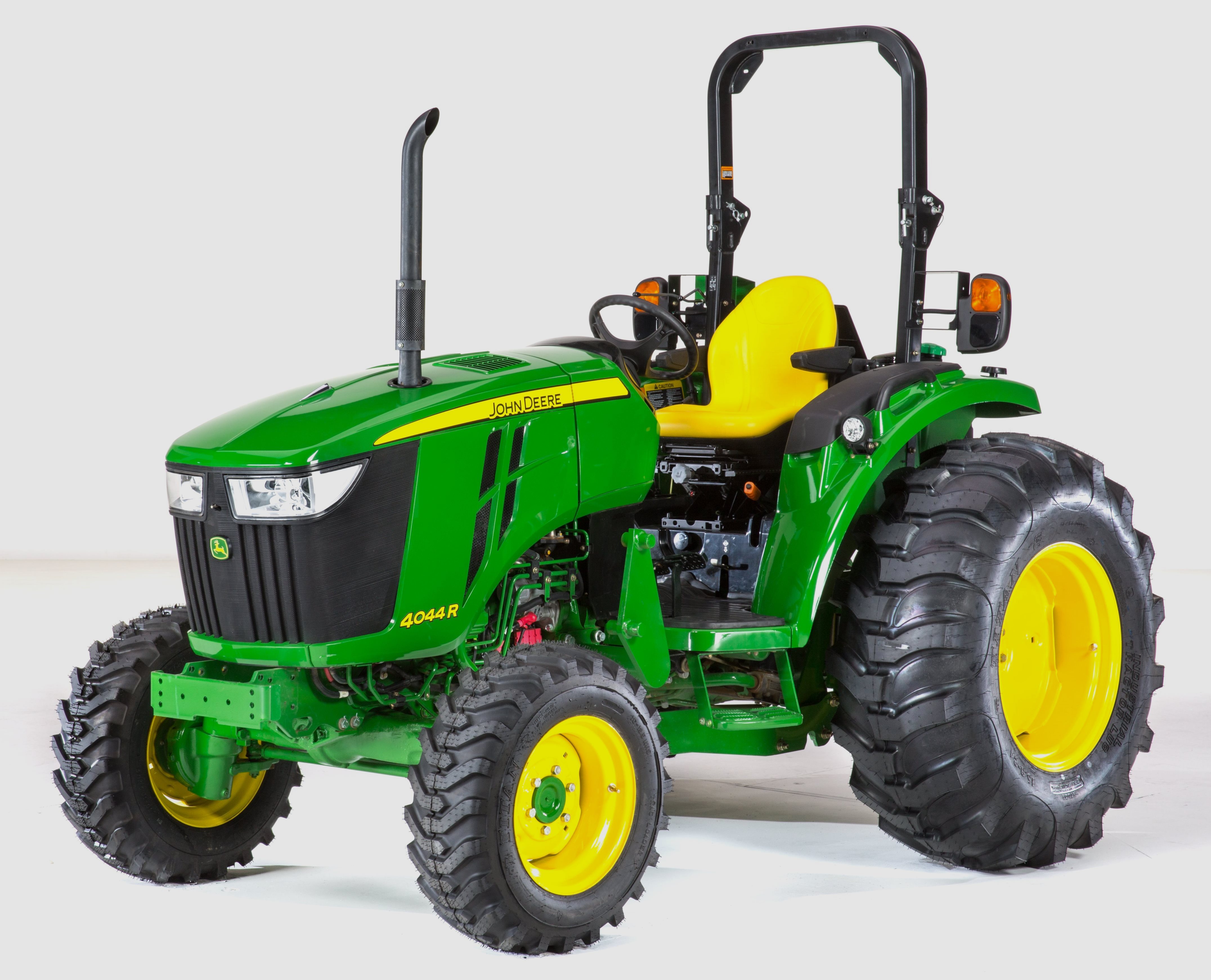 JD 4044R
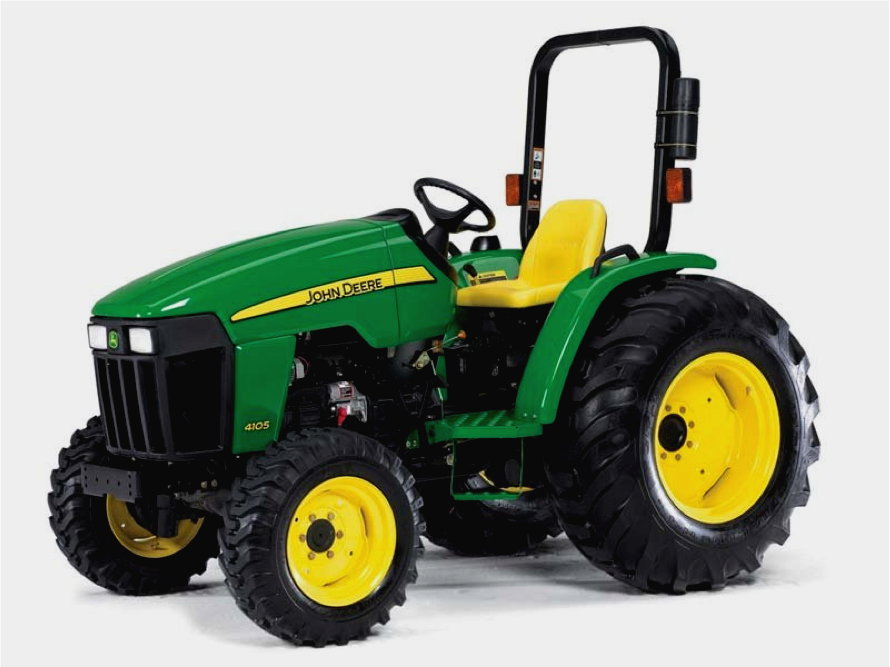 JD 4105
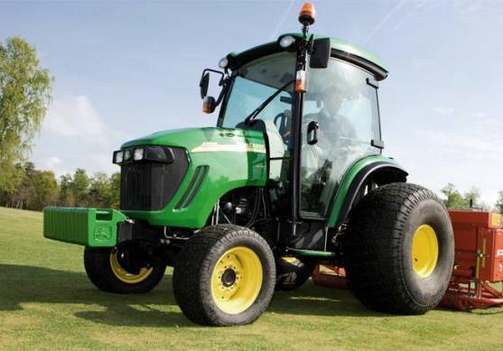 JD 4720
________________________________________________________________________________________
 420 Loader
 419 Loader
 510 Loader
 512 Loader
 520 Loader
________________________________________________________________________________________
 520M Loader
 540M NSL
 540 Loader
 440R Loader
 H180 Loader
________________________________________________________________________________________
________________________________________________________________________________________
 JD 5045E
 JD 5085E
 JD 5100M
 JD 6105R
 JD 6120M
________________________________________________________________________________________
 JD 6155M
 JD 6195R
 JD 6210R
 JD 7210R
 JD 7250R
________________________________________________________________________________________
 JD 7310R
 JD 8245R
 JD 8295R
 JD 8370R
 JD 9370R
________________________________________________________________________________________
 120R Loader
 D120 Loader
 H120 Loader
 45 Loader
 200CX Loader
________________________________________________________________________________________
 D160 Loader
 D170 Loader
 H160 Loader
 H165 Loader
 H240 Loader
________________________________________________________________________________________
 210 Loader
 220R Loader
 300E Loader
 300X Loader
 300CX Loader
________________________________________________________________________________________
 JD 9420R
 JD 9510R
 JD GX335
 JD GX85
 JD LA105
________________________________________________________________________________________
 JD 5065M
 JD 5055D
 JD 5115R
 JD 5105M
 JD 6110R
________________________________________________________________________________________
 JD 6130D
 JD 6225
 JD 7530
 JD 4044M
 JD 7185J
________________________________________________________________________________________
 300 Loader
 300R Loader
 320R Loader
 400E Loader
 410 Loader
________________________________________________________________________________________
 430 Loader
 460 Loader
 521 Loader
 531 Loader
 541 Loader
________________________________________________________________________________________
 551 Loader
 631 Loader
 651 Loader
 661 Loader
 603R Loader
________________________________________________________________________________________
 JD D130
 JD D160
 JD 325
 JD 335
 JD 345
________________________________________________________________________________________
 JD 2520
 JD 3005
 JD 3720
 JD 1025R
 JD 3033R
________________________________________________________________________________________
 JD 5090EL
 JD 5100MH
 JD 5075GV
 JD 6090RC
 JD 6110B
________________________________________________________________________________________
 623R Loader
 643R Loader
 731 Loader
 746 Loader
 751 Loader
________________________________________________________________________________________
 533 Loader
 583 Loader
 633 Loader
 653 Loader
 683 Loader
________________________________________________________________________________________
 H260 Loader
 663R Loader
 663 Loader
 683R Loader
 753 Loader
________________________________________________________________________________________
 JD 6125J
 JD 6150RH
 JD 6210J
 JD 7195J
 JD 8310
________________________________________________________________________________________
 JD 6325
 JD 5525
 JD 5083EN
 JD 5100GN
 JD 5125R
________________________________________________________________________________________
 210C Backhoe
 300D Backhoe
 310G Backhoe
 410G Backhoe
 710G Backhoe
________________________________________________________________________________________
 80 Loader
 100 Loader
 146 Loader
 148 Loader
 158 Loader
________________________________________________________________________________________
 168 Loader
 175 Loader
 522 Loader
 542 Loader
 540R Loader
________________________________________________________________________________________
 562 Loader
 563 Loader
 673 Loader
 741 Loader
________________________________________________________________________________________
 L108 Automatic
 L120 Automatic
 LA110 Automatic
 LA120 Automatic
 LA150 Automatic
________________________________________________________________________________________
 LT155
LT155 LT160 Automatic
 LT180 Automatic
 LTR180
 X165
X165________________________________________________________________________________________
 E100
E100 E120
E120 E150
E150 LTR166
________________________________________________________________________________________
 LA135
LA135 LA165
LA165 LX277
LX277 LX288
LX288 LX255
LX255________________________________________________________________________________________
 S240
S240 GT235
GT235 G110 Automatic
 JD 3203
 JD 5520
________________________________________________________________________________________
 JD 316
 JD 420
 JD 425
 JD 445
________________________________________________________________________________________
 JD_5050D
 X300
X300 X304
X304 X310
X310 X110 Automatic
________________________________________________________________________________________
 H310 Loader
 H340 Loader
 H360 Loader
 H380 Loader
 H480 Loader
________________________________________________________________________________________
 240 Loader
 245 Loader
 260 Loader
 265 Loader
 280 Loader
________________________________________________________________________________________
 600R Loader
 620R Loader
 640R Loader
 660R Loader
 680R Loader
________________________________________________________________________________________
 JD_5039D
 X146R
X146R X360
X360 X155R
X155R X140 Automatic
________________________________________________________________________________________
 X350
X350 X380
X380 X500
X500 X590
X590 X700
X700________________________________________________________________________________________
 3036E
3036E 2038R
2038R 3038R
3038R 4049M
4049M JD 4100
________________________________________________________________________________________
 X738
X738 X740
X740 X748
X748 X749
X749 X950R
X950R________________________________________________________________________________________
 JD 4510
 5045D
5045D 5050E
5050E 5060E
5060E 5078E
5078E