________________________________________________________________________________
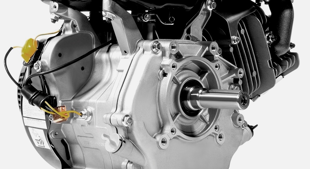
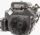
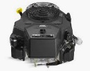
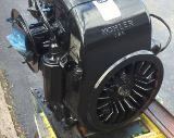
Kohler CV16S Engine - Nikki Carburetor
Kohler CV16S - Nikki Carburetor Adjustment
Kohler CV16S engines are equipped with fixed main jet Nikki carburetors.
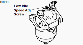
Nikki carburetors only have a low idle speed screw. Carburetors will
have fixed idle fuel or a limiter cap on the idle fuel adjusting needle.
Carburetor adjustments should be made only after the engine has warmed
up. The carburetor is designed to deliver the correct fuel to air
mixture to the engine under all operating conditions. The main fuel jet
is calibrated at the factory and is not adjustable.
The idle fuel adjusting needle is also set at the factory and normally
does not need adjustment. Engines operating at altitudes above
approximately 1830 m (6000 ft.) may require a special high altitude main
jet. If, however, the engine is hard-starting or does not operate
properly, it may be necessary to adjust or service the carburetor.
Low Idle Speed Setting
1) Start the engine and run at half throttle for 5 to 10 minutes to warm
up. The engine must be warm before doing step 2.
2) Low Idle Speed Setting: Place the throttle control into the idle or
slow position. Set the low idle speed to 1200 RPM (±75 RPM) by turning
the low idle speed adjusting screw in or out. Check the speed using a
tachometer. The actual low idle speed depends on the application refer
to equipment manufacturer's recommendations. The recommended low idle
speed for basic engines is 1200 RPM. To ensure best results when setting
the low idle fuel needle, the low idle speed must not exceed 1200 RPM
(±75 RPM).
Kohler CV16S - Nikki Carburetor Disassembly
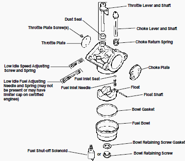
- Remove the bowl retaining screw, retaining screw gasket, and fuel
bowl.
- Remove the bowl gasket, float shaft, float, and fuel inlet needle.
- Remove the low idle speed screw and spring.
- If there is a low fuel adjusting needle without a limiter cap, remove
the needle and spring.
- Do not attempt to remove the needle if it has a limiter cap.
- Further disassembly to remove the welch plugs, main fuel jet, fuel
inlet seat, throttle plate and shaft, and choke plate and shaft is
recommended only if these parts are to be cleaned or replaced.
Main Fuel Jet Removal
The main jet on Nikki carburetors is threaded into the tip of the fuel
shut-off solenoid. It can be removed for inspection or cleaning.
Fuel Inlet Seat Removal
The fuel inlet seat is pressed into the carburetor body, do not attempt
to remove it. If necessary, clean it in place with aerosol carburetor
cleaner.
Choke Shaft Removal (Self-Relieving)
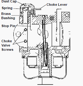
The self-relieving choke used on some carburetors. Use the following
procedure to replace the self-relieving choke components using Choke
Repair Kit. Remove the black dust cover. This cover snaps on and off.
Remove and discard the two screws fastening the choke plate to the choke
shaft. Remove and discard the choke plate and choke shaft from the
carburetor.
Remove the upper brass bushing using one of the following
procedures: Use a slide hammer type bearing puller. Use a screw
extractor (for 5/32 dia. hole). Secure extractor in a vise. Turn
carburetor on to the extractor. While pulling on the carburetor, lightly
tap the carburetor casting with a hammer or use a size 12-28 tap if a
screw extractor is not available.
Kohler CV16S - Nikki Carburetor Cleaning
- Carburetor body and bore; especially the areas where the throttle
plate, choke plate and shafts are seated.
- Idle fuel and idle ports in carburetor bore, main jet, bowl vent, and
fuel inlet needle and seat.
- Float and float hinge. Fuel bowl.
- Throttle plate, choke plate, throttle shaft, and choke shaft.
- Do not submerge the carburetor in cleaner or solvent when fiber,
rubber, or foam seals or gaskets are installed.
- The cleaner may damage these components.
Kohler CV16S - Nikki Carburetor Reassembly
Choke Shaft Installation (Self-Relieving)
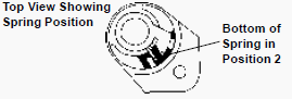
Before installing kit parts, thoroughly clean the carburetor body with
compressed air. Install the new bushing through the new lever and align
the slot in the bottom of the lever over the lever stop pin. To ensure
the proper alignment of the upper bushing and the lower shaft hole use a
3/16 diameter drill blank to align the bushing as it is pressed into the
casting.
Install choke shaft and spring assembly with the lower spring tang installed in the second notch from the right. Loosely attach the choke plate to the choke shaft using the two screws provided in the choke repair kit. Apply Loctite to the threads of the choke plate retaining screws.
Secure these screws only after the choke plate is
properly aligned in the choke bore. To align choke plate, insert a 0.010
in. shim between the top right edge of the choke plate and bore. Then
while pushing down on the top of the choke shaft, tighten screws
securely.

Check choke shaft and choke plate for freedom of movement by performing
the following: Using the choke lever, close the choke plate. The choke
lever and choke plate should move in unison. While holding the choke
lever in the closed position, push on the long side of the choke plate.
The choke plate should open and spring closed freely.
While holding the
choke lever in the wide open position, the choke plate should be against
the wide open choke plate stop pin. Install new dust cover by pushing it
down until it snaps into place. After the carburetor is reinstalled on
the engine, recheck choke system for freedom of movement by moving the
wire link in the direction to close the choke and releasing it. The link
should move freely in both directions.
High Altitude Operation
When operating the engine at altitudes of 1830 m (6000 ft.) and above,
the main fuel mixture tends to get overrich. An overrich mixture can
cause conditions such as black, sooty exhaust smoke, misfiring, loss of
speed and power, poor fuel economy, and poor or slow governor response.
To compensate for the effects of high altitude, a special high altitude main fuel jet can be installed. High altitude jets are sold in kits which include the jet and necessary gaskets. Refer to the Parts Manual for the engine being serviced for the correct kit number.
________________________________________________________________________________
________________________________________________________________________________________
| KOHLER ENGINES SPECS AND SERVICE DATA |
 CH12.5
 CH14S
CH14S CH15S
CH15S CH16
CH16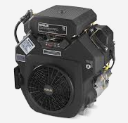 CH18S
CH18S________________________________________________________________________________________
 CH23S
CH23S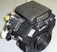 CH25S
CH25S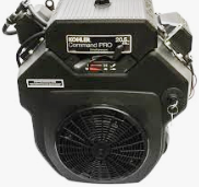 CH640S
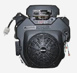 CH730S
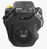 CH750S
________________________________________________________________________________________
________________________________________________________________________________________
 CV15S
CV15S CV16S
CV16S CV18S
CV18S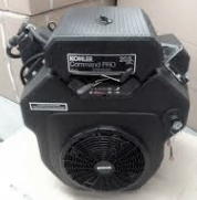 CV20S
CV20S CV22S
CV22S________________________________________________________________________________________
 CV23S
CV23S CV25S
CV25S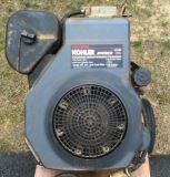 CV490S
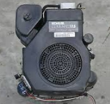 CV491S
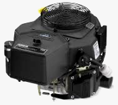 CV730S
________________________________________________________________________________________
 CV740S
 K161
K161 K181
K181 K241
K241 K301
K301________________________________________________________________________________________
 K321
K321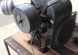 K341
K341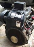 K361
K361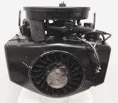 M18
M18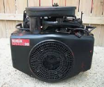 M20
M20________________________________________________________________________________________
 SV470S
 SV530S
 SV540S
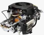 SV590S
 SV600S
________________________________________________________________________________________
 SV710
SV710 SV715
SV715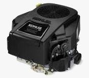 SV725S
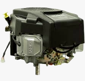 SV730S
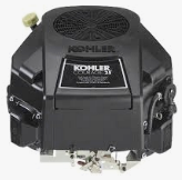 SV735
SV735________________________________________________________________________________________
| KAWASAKI ENGINES SPECS AND SERVICE DATA |
 FA210
FA210 FA210D
 FB460V
 FC150V
 FC290V
________________________________________________________________________________________
 FC420V
 FC540V
 FD501V
 FD590V
 FD620D
________________________________________________________________________________________
 FD731V
 FD750D
 FH430V
 FH500V
 FH531V
________________________________________________________________________________________
 FH580V
 FH601V
 FH680V
 FS541V
 FS600V
________________________________________________________________________________________
 FS651V
 FX651V
 FX691V
 FX730V
________________________________________________________________________________________
 FH541V
 FH641V
 FH661V
 FH721V
 FS730V
________________________________________________________________________________________
| BRIGGS AND STRATTON ENGINES SPECIFICATIONS |
 252707
 253707
 282707
 286707
 303777
________________________________________________________________________________________
 28N707
 28M707
 28Q777
 28R707
 28S777
________________________________________________________________________________________
 311707
 31A607
 31C707
 31N707
 31Q777
________________________________________________________________________________________
 31R977
 31R777
 31P777
 31P977
 350777
________________________________________________________________________________________
 402707
 422707
 42A707
 331777
 331877
________________________________________________________________________________________
| HONDA ENGINES SPECS AND SERVICE DATA |
 G50
G50 G100
G100 GC135
GC135 GC160
GC160 GC190
GC190________________________________________________________________________________________
 GS190
GS190 GX100
GX100 GX120
GX120 GX160
GX160 GX200
GX200________________________________________________________________________________________
 GXV120
 GXV160
 GXV270
 GXV340
 GXV390
________________________________________________________________________________________
 GXV610
 GCV520
 GCV530
 GXV620
 GXV630
________________________________________________________________________________________
 GCV145
 GCV160
 GCV170
 GCV190
 GCV200
________________________________________________________________________________________
 GSV190
 GX110
GX110 GX140
GX140 GV100
GV100 GXV140
________________________________________________________________________________________