________________________________________________________________________________
Kubota B1502, B1610, B4200 - Mechanical Transmission
Kubota B1502, B1610, B4200 Transmission
Troubleshooting
Problem - Noise from Transmission
Transmission oil insufficient - Refill.
Gear worn or broken - Replace.
Improper backlash between ring gear and spiral bevel pinion shaft -
Adjust.
Improper backlash between differential pinion and differential side gear
- Adjust.
Bearings worn - Replace.
Problem - Gear Slip out of Mesh
Shift fork spring tension insufficient - Replace.
Shift fork or shifter worn - Replace.
Shift fork bent - Replace.
Problem - Differential Lock Cannot Be Set
Differential lock pedal play excessive - Adjust.
Differential lock shift fork broken - Replace.
Differential lock clutch broken - Replace.
Problem - Differential Lock Pedal Does Not Return
Differential lock spring broken or fall - Replace or Assemble.
Differential lock spring tension insufficient - Replace.
Kubota B1502, B1610, B4200 Single Plate Clutch
- Checking and Adjusting
Clutch Pedal Play
Depress the clutch pedal by hand, and measure the amount of pedal
movement. If the measurement is not within the factory specifications,
adjust the play by turning the rod. Clutch pedal play - 20 to 30 mm 0.79
to 1.18 in.
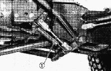
Clutch Pedal Traveling
Measure the distance between clutch rod and clutch adjusting screw. If
the measurement is not within the factory specifications, adjust it with
the clutch adjusting screw. After adjustment, secure the clutch
adjusting screw with the lock nut. Distance between clutch rod and
clutch adjusting screw - 11 to 13 mm 0.43 to 0.51 in.
Clearance between Safety Switch and Clutch Rod
Measure the clearance between safety switch and clutch rod with a feeler
gauge. If the clearance is not within the factory specifications, adjust
the mounting position of switch. Clearance between safety switch and
clutch rod - 4.5 to 5.0 mm 0.177 to 0.197 in.
Kubota B1502, B1610, B4200 Single Plate Clutch
- Disassembly And Assembly
Separation of Clutch Assembly
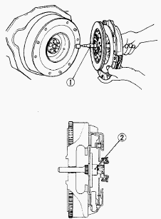
1 - Clutch center tool, 2 - Clutch disc boss
Separate the clutch assembly from the flywheel. Install the clutch
assembly with the clutch center tool (1). Face the longer end of the
clutch disc boss (2) rearward.
Clutch Rod and Clutch Release Fork
Remove the front step frame LH. Remove the cotter pin at the end of the
clutch rod, and remove the clutch release fork and clutch rod. Set the
fork in the correct direction.
Release Bearing Holder
Remove the spring mounting screw and spring. Remove the grease nipple.
Pull out the release bearing holder toward the front of the housing.
Kubota B1502, B1610, B4200 Tractor - Single
Plate Clutch Service
Backlash between Clutch Disc and Propeller Shaft
Mount the clutch disc onto the propeller shaft. Fix the rule on the
housing. Hold the propeller shaft so that it does not rotate. Slightly
move the disc and measure the displacement around disc edge. If the
measurement exceeds the allowable limit, replace clutch disc.
Displacement around disc edge (Allowable limit) - 2.0 mm 0.079 in.
Clutch Disc Wear
Measure the depth from clutch disc surface to the top of rivet at least
10 points with a depth gauge. If the depth is less than the allowable
limit, replace. If oil is sticking to the clutch disc, or disc surface
is carbonized, replace clutch disc. Depth to rivet top (Allowable limit)
- 0.3 mm 0.012 in.
Pressure Plate Flatness
Place a straightedge on the pressure plate and measure clearance with a
feeler gauge at several points. If the clearance exceeds allowable
limit, replace pressure plate. When the pressure plate is worn around
its outside and its inside surface only is in contact with the
straightedge, replace it even if the clearance is within the allowable
limit. Clearance between pressure plate and straight edge (Allowable
limit) - 0.2 mm 0.008 in.
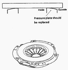
Checking Pressure Plate and Diaphragm
Check the pressure plate and if scratched on its surface, correct with
sandpaper or replace it. Check the diaphragm for cracks and scratches.
If defects are found, replace it.
Checking Clutch Release Bearing
Check the clutch release bearing. If surface is worn excessively, or
abnormal sounds occur, replace it.
Kubota B1502, B1610, B4200 Transmission Case -
Disassembling And Assembling
Shaft Cover 1
Remove the shaft cover 1. Be sure to replace the gasket with a new one.
1st Shaft
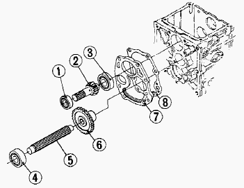
1 - Bearing, 2 - 1st Shaft, 3 - Bearing, 4 - Bearing, 5 - 2nd Shaft, 6 -
29T Gear, 7 - Cover Spacer, 8 - Gasket
Remove the bearing (1) on the 1st shaft (2) with a special-use puller
set. Remove the bearing (4) and 29T gear (6) on the 2nd shaft (5) with a
special-use puller set. Remove the 1 st shaft with the cover spacer (7).
Be sure to replace the gasket (8) with a new one.
Fork Shaft and Shift Fork
Remove the shaft lock screw. Screw M8 screw (pitch 1.25 x 70 mm long,
pitch 1.25 x 2.76 in. long) into the fork shaft, and tap out it to the
rear. Remove the shift fork. Install the fork shaft with the groove (4)
facing the differential gear case.
Spiral Bevel Pinion Shaft
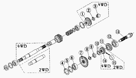
1 - 24T gear, 2 - Collar, 3 - Needle Bearing, 4 - Spacer, 5 - Shim, 6 -
Bearing, 7 - 13T-32T Gear, 8 - External Snap Ring, 9 - Collar, 10 - Stop
Collar, 11 - Bearing, 12 - Bearing, 13 - Spiral Bevel Pinion Shaft, 14 -
16T Gear, 15 - Pinion Collar, 16 - Drum
Remove the rod and drum (16). Draw out the spiral bevel pinion shaft
(13) Remove the 24T gear (1) (4WD type only).
4th Shaft
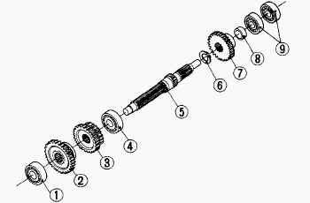
1 - Bearing, 2 - 30T Gear, 3 - 13T-17T Gear, 4 - Bearing, 5 - 4th Shaft,
6 - External Snap Ring, 7 - 19T Gear, 8 - Collar, 9 - Bearing
Remove the external snap ring (6). Set a wood piece, and tap out the 4th
shaft (5) to the rear to remove the bearing (1). Remove the 30T gear (2)
and 13T-17T gear (3), and pull out the 4th shaft(5).
2nd Shaft
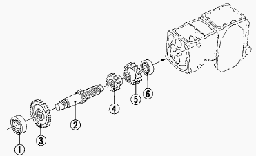
1 - Bearing, 2 - 2nd Shaft with 13T Gear, 3 - 29T Gear, 4 - 13T Gear, 5
- 17T Gear, 6 - Bearing
Draw out the 2nd shaft (2) to the rear.
Reverse Shaft
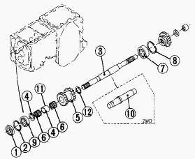
1 - Oil Seal, 2 - Internal Snap Ring, 3 - Reverse Shaft (4WD), 4 -
Collar, 5 - 16T-20T Gear, 6 - Needle Bearing, 7 - Bearing, 8 - Internal
Snap Ring, 9 - Bearing, 10 - Reverse Shaft (2WD), 11 - Collar 1, 12 -
Collar,
Remove the internal snap ring (8), and tap out the reverse shaft (3 or
10) to the rear.
3rd Shaft
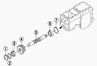
1 - Internal Snap Ring, 2 - Shim, 3 - Bearing, 4 - 17T-13T Gear, 5 - 3rd
Shaft, 6 - Bearing, 7 - Internal Snap Ring
Remove the internal snap ring (7). Set a wood piece, and tap out the 3rd
shaft (5) to the rear to remove the bearing (3). Remove the 17T-13T gear
(4) and pull out the 3rd shaft (5).
PTO Fork Shaft and Mid-PTO
Tap out the PTO fork shaft to the front. The 19T Gear is used for the
gear transmission instead of the 24T Gear.
Kubota B1502, B1610, B4200 Tractor -
Transmission Case Servicing
Checking Bearing
Hold the inner race, and push and pull the outer race in all directions
to check for wear and roughness. Apply transmission oil to the bearing,
and hold the inner race. Then, turn the outer race to check rotation. If
there is any defect, replace it.
Gear Backlash
Set a dial indicator (lever type) with its finger on the tooth surface.
Move the gear to measure the backlash, while holding the mating gear. If
the measurement exceeds the allowable limit, replace it. Gear backlash -
0.10 to 0.20 mm (0.004 to 0.008 in). Allowable limit - 0.4 mm (0.006
in).
Clearance between Shift Fork and Shift Gear Groove
Place the shift fork in the shift gear groove and measure the clearance
with a feeler gauge. If the clearance exceeds the allowable limit,
replace it. Clearance between shift fork and shift gear groove - 0.10 to
0.35 mm (0.004 to 0.014 in). Allowable limit - 0.5 mm (0.020 in).
Clearance between 16T-20T Gear and Reverse Shaft
Measure the 16T-20T gear I.D. with an inside micrometer, and then
reverse shaft O.D. with an outside micrometer. Measure the O.D. of two
needles in the needle bearing with an outside micrometer. Clearance is
the difference between the gear I.D. and the sum of shaft O.D. and two
needle O.D. If the clearance exceeds the allowable limit, replace.
Clearance between 16T-20T gear and reverse shaft - 0.007 to 0.0045 mm
(0.0003 to 0.0018 in). Allowable limit - 0.1 mm (0.0039 in). Reverse
shaft O.D. - 21.967 to 21.980 mm (0.8648 to 0.8654 in). 16T-20T gear
I.D. - 25.987 to 26.000 mm (1.0231 to 1.0236 in). Needle O.D. - 1.994 to
2.000 mm (0.0785 to 0.0787 in).
Kubota B1502, B1610, B4200 Differential Gear
Case - Disassembly And Assembly
Differential Assembly
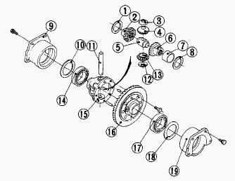
1 - Shim, 2 - Differential Side Gear, 3 - Differential Pinion Collar, 4
- Differential Pinion, 5 - Thrust Collar, 6 - Differential Side Gear, 7
- Ring Gear Bushing, 8 - Shim, 9 - Differential Bearing Holder (RH), 10
- Differential Side Shim, 11 - Differential Pinion Shaft, 12 -
Differential Pinion Collar, 13 - Differential Pinion, 14 - Bearing, 15 -
Differential Case, 16 - Ring Gear, 17 - Bearing, 18 - Differential Side
Shim, 19 - Differential Bearing Holder (LH)
Remove the left and right differential bearing holders (19), (9). Take
out the differential assembly from the differential gear case. Install
the differential assembly, noting the number of differential side shims
(10), (18).
5th Shaft
Remove the external snap ring, and remove the drum and spring. Remove
the rear cover mounting screws. Remove the 5th shaft with the PTO shaft.
РТО Shaft
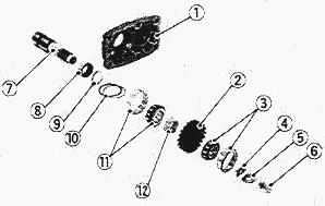
1 - Rear Cover, 2 - 22T Gear, 3 - Taper Roller Bearing, 4 - Washer, 5 -
Lock Washer, 6 - Screw, 7 - PTO Shaft, 8 - Bushing, 9 - PTO Collar, 10 -
PTO Shim, 11 - Taper Roller Bearing, 12 - PTO Collar
Flatten the lock washer (5). Remove the screw (6), plain washer, lock
washer (5), washer (4) and straight pin. Tap out the PTO shaft (7) to
the rear. Replace the lock washer with a new one, be sure to adjust the
turning torque of PTO shaft. Lock the screw with the lock washer after
adjusting the turning torque. Tightening torque Screw - 18.6 to 32.4 Nm
(13.7 to 23.9 ft-lbs).
Kubota B1502, B1610, B4200 Tractor - Differential Gear
Case Service
Initial Turning Torque of PTO Shaft
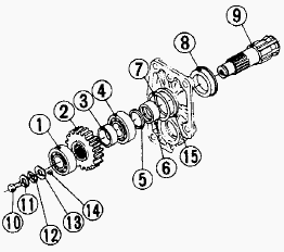
1 - Taper Roller Bearing, 2 - 22T Gear, 3 - PTO Collar, 4 - Taper Roller
Bearing, 5 - PTO Collar, 6 - Bushing, 7 - PTO Bearing Collar, 8 - Oil
Seal, 9 - PTO Shaft, 10 - Screw, 11 - Plain Washer, 12 - Lock Washer, 13
- Washer, 14 - Straight Pin, 15 - Shim
Tighten the screw (10) to the specified torque (18.6 to 32.4 Nm, 13.7 to
23.9 ft-lbs). Install the PTO shaft to the rear cover, and install it to
the differential gear case. Screw the screw (M 10 x Pitch 1.25) in PTO
shaft (9), and set a torque wrench to it. Turn the PTO shaft with a
torque wrench to measure the initial turning torque. If the initial
turning torque is not within the factory specifications, adjust the
turning torque with the shims (15). Initial turning torque - 0.49 to
1.47 Nm (0.36 to 1.08 ft-lbs). Thickness of shims: 0.3 mm (0.012 in.),
0.4mm (0.016 in.), 0.5 mm (0.020 in.). Lock the screw (10) with the lock
washer (12) after adjusting the turning torque.
Backlash between Ring Gear and Spiral Bevel Pinion Shaft
Set a dial indicator (lever type) on the ring gear. Measure the backlash
by fixing the spiral bevel pinion shaft and moving the ring gear by
hand. When the backlash is too small, decrease the number of shims in
the side of the ring gear, and insert the removed shims in the opposite
side. When the backlash is too large, decrease the number of shims in
the side of the differential case, and insert the removed shims in the
opposite side. Adjust the backlash properly by repeating the above
procedure. Backlash between ring gear and spiral bevel pinion shaft -
0.1 to0.2 mm (0.004 to 0.008 in). Allowable limit - 0.4 mm (0.016 in).
________________________________________________________________________________
________________________________________________________________________________________
________________________________________________________________________________________
| KUBOTA TRACTORS SPECIFICATIONS |
________________________________________________________________________________________
________________________________________________________________________________________
________________________________________________________________________________________
________________________________________________________________________________________
________________________________________________________________________________________
________________________________________________________________________________________
________________________________________________________________________________________
________________________________________________________________________________________
________________________________________________________________________________________
________________________________________________________________________________________
________________________________________________________________________________________
________________________________________________________________________________________
________________________________________________________________________________________
________________________________________________________________________________________
________________________________________________________________________________________
| KUBOTA ENGINES DATA AND SERVICE SPECS |
________________________________________________________________________________________
________________________________________________________________________________________
________________________________________________________________________________________
________________________________________________________________________________________
________________________________________________________________________________________
| KUBOTA FRONT END LOADERS |
________________________________________________________________________________________
________________________________________________________________________________________
________________________________________________________________________________________
________________________________________________________________________________________
________________________________________________________________________________________
________________________________________________________________________________________
________________________________________________________________________________________
________________________________________________________________________________________
________________________________________________________________________________________
________________________________________________________________________________________
________________________________________________________________________________________
________________________________________________________________________________________
| KUBOTA TRACTORS TROUBLESHOOTING | ||||
| L235 | L2501 | L2550 | L275 | L3110 |
| L3301 | L35 | L3710 | L3901 | L4310 |
| L5030 | M4700 | M5700 | M6040 | M6800 |
| M8200 | M8540 | M9000 | MX5100 | MX5200 |

 SPECIFICATIONS
 LOADERS
 ENGINES
 MAINTENANCE
 PROBLEMS
 B1241
B1241 B1600
B1600 B1700
B1700 B1750
B1750 B21 Backhoe
 B2150
B2150 B2301
B2301 B2320
B2320 B2530
B2530 B26 Backhoe
 B2601
B2601 B2650HSD
 B3030
B3030 B3350
B3350 B6000
B6000 B6100
B6100 B6200
B6200 B7000
B7000 B7001
B7001 B7100HST
 B7200
B7200 B7500
B7500 B7510
B7510 B7800
B7800 B8200HST
 BX1880
 BX2200
 BX2230
 BX2350
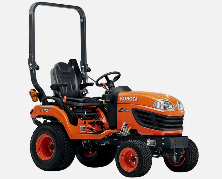 BX2370
 BX23S
BX23S BX25 TLB
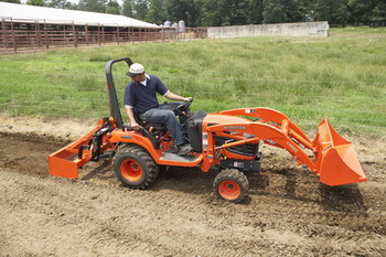 BX2660
 BX2680
 F3680
F3680 L175
L175 L185
L185 L210
L210 L225
L225 L235
L235 L245
L245 L260
L260 L275
L275 L285
L285 L305
L305 GR2120
 L1501
L1501 L2350
L2350 L2550
L2550 L2800
L2800 L3010
L3010 L3200HST
 L3301
L3301 L3560
L3560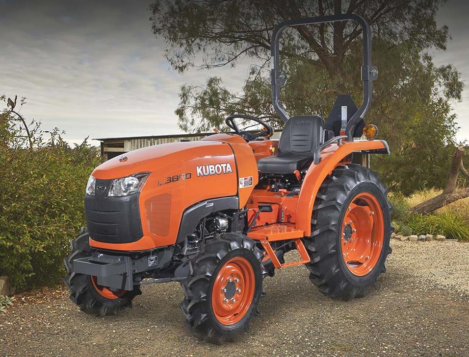 L3800
L3800 L4701
L4701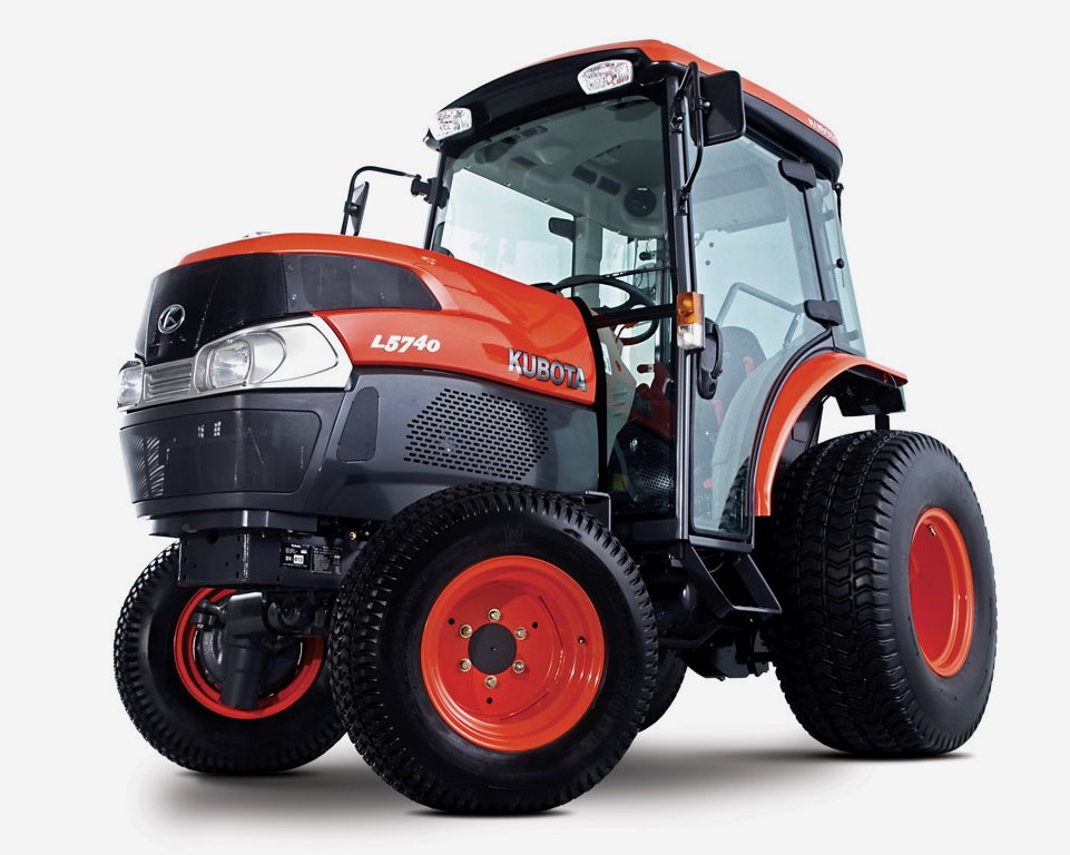 L5740
L5740 M5-091
 M5-111
 M6060
M6060 M7040
M7040 M9540
M9540 M9960
M9960 MX5100
 D662
D662 D722
D722 D750
D750 D782
D782 D850
D850 D902
D902 D905
D905 D950
D950 D1005
D1005 D1100
D1100 D1105
D1105 D1503
D1503 D1703
D1703 D1803
D1803 V1200
V1200 V1205
V1205 V1305
V1305 V1505
V1505 V2203
V2203 V2403
V2403 Z482
Z482 Z602
Z602 Z750
Z750 Z1100
Z1100 Z1300
Z1300 B1630
B1630 BF400
BF400 BF400G
 LA181
LA181 LA203
LA203 LA211
LA211 LA243
LA243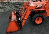 LA271
LA271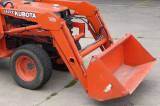 LA272
LA272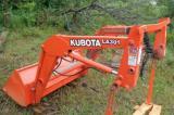 LA301
LA301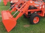 LA302
LA302 LA304
LA304 LA340
LA340 LA344
LA344 LA351
LA351 LA352
LA352 LA364
LA364 LA401
LA401 LA402
LA402 LA434
LA434 LA463
LA463 LA481
LA481 LA482
LA482 LA504
LA504 LA513
LA513 LA514
LA514 LA524
LA524 LA525
LA525 LA534
LA534 LA555
LA555 LA680
LA680 LA681
LA681 LA682
LA682 LA703
LA703 LA714
LA714 LA723
LA723 LA724
LA724 LA764
LA764 LA765
LA765 LA805
LA805 LA844
LA844 LA852
LA852 LA853
LA853 LA854
LA854 LA1002
 LA1055
 LA1065
 LA1153
 LA1154
 LA1251
 LA1301S
 LA1353
 LA1403
 LA1601S
 LA1854
 LA1944
 LA1953
 LA2253
 LM2605