________________________________________________________________________________
Kubota B1700, B2400 - Transmission and PTO
Kubota B1700, B2400 - Transmission Components
Main Gear Shift Section
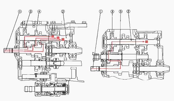
1 - 2nd Gear Shaft with 13T, 13T and 18T Gear, 2 - 4th Shaft with 11T
Gear, 3 - 30T Shifter Gear, 4 - 17T-13T Shafter Gear, 5 - 16T-20T Gear
Besides neutral, four kinds of power flow (from clutch shaft to 4th
shaft) are available by operating the main gear shift lever to shift
positions on the 30T shifter gear (3) and 17T-13T shifter gear (4) on
the 4th shaft (2).
1st Position: 2nd Gear Shaft with 13T Gear (1) - 30T Shifter Gear (3) -
4th Shaft (2). 2nd Position: 2nd Gear Shaft with 13T Gear (1) - 17T-13T-
Shifter Gear (4) - 4th Shaft (2). 3rd Position: 2nd Gear Shaft with 18T
Gear (1) - 17T-13T Shifter Gear (4) - 4th Shaft (2). Reverse Position:
2nd Gear Shaft with 13T Gear (1) - 16T-20T Gear (5) - 30T Shifter Gear
(3) - 4th Shaft (2).
Hi-Lo Gear Shift Section
Two kinds of power flow (from 4th shaft to spiral bevel pinion shaft)
are available by operating the high-low gear shift lever to shift the
gear on the spiral bevel pinion shaft. Low Position - 4th Gear Shaft -
Shifter Gear - Spiral Bevel Pinion Shaft. High Position - 4th Shaft -
Gear - Shifter Gear - Bevel Pinion Shaft.
Front Wheel Drive Section
2-wheel drive or 4-wheel drive is selected by changing the position of
20T shift gear with the front wheel drive lever. When the front wheel
drive lever is set to "Disengaged," the 20T shift gear is neutral and
power is not transmitted to the front wheel drive shaft. When the front
wheel drive lever is set to "Engaged," the 20T shift gear slides to the
right to engage with 13T gear on the spiral bevel pinion shaft.
Therefore, the front drive shaft is actuated to drive the front wheels.
Kubota B1700, B2400 Tractor - Clutch
This tractor is used dry single plate type clutch. The clutch is located
between the engine and transmission and is operated by stepping on the
clutch pedal. When the clutch pedal is depressed, the clutch is
disengaged and when it is released, the clutch is engaged and power from
the engine is transmitted to the transmission.
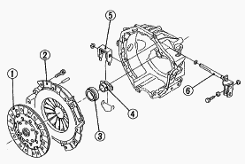
1 - Clutch Disc, 2 - Pressure Plate Assembly, 3 - Release Bearing, 4 -
Release Rod, 5 - Release Fork, 6 - Clutch Rod
Engine torque is transmitted to the pressure plate assembly via the
flywheel (1) which is connected to the engine crankshaft. Therefore, the
clutch cover constantly runs with engine. The clutch disc (10) is
located between the flywheel (1) and the pressure plate (3) of pressure
plate assembly. Torque is transmitted to the clutch disc (10) by the
pressure created by diaphragm spring (4) installed in pressure plate
assembly. Then, the torque is transmitted to the transmission via the
clutch shaft (9). When the pedal (13) is depressed, the clutch release
hub (7) and the clutch release bearing (6) move towards the flywheel and
push the fingers of the diaphragm spring (4). In other words, this
movement pulls the pressure plate (3) up and disengages the clutch.
Clutch Engaged
When the clutch pedal is not depressed, the clutch release bearing (6)
and the fingers of diaphragm spring (4) are not connected to each other.
Accordingly, the pressure plate (2) is tightly pressed against the
flywheel (1) by the diaphragm spring (4). As a result, rotation of the
flywheel (1) is transmitted to the transmission through the clutch shaft
(8) due to the frictional force among the flywheel (1), clutch disc (10)
and pressure plate (2).
Clutch Disengaged
When the clutch pedal is depressed, the clutch rod is pulled to move the
clutch lever (11). Then, the release fork (9) pushes the release hub (7)
and release bearing (6) toward the flywheel. Simultaneously, the release
bearing (6) pushes the diaphragm spring (4). As the pressure plate (2)
is pulled by the diaphragm spring (4), the frictional force among the
flywheel (1), clutch disc (10) and pressure plate (2) disappears.
Therefore, rotation of the flywheel (1) is not transmitted to the clutch
disc (10), and then the rotation of the clutch shaft (8) stops.
Kubota B1700, B2400 Clutch - Checking And Adjusting
Clutch Pedal Free Travel
When checking, park the tractor on flat ground, apply the parking brake,
stop the engine and remove the key. Slightly depress the clutch pedal
and measure free travel at top of pedal stroke. If the measurement is
not within the factory specifications, loosen the lock nut and adjust
the clutch rod length. After adjusting it, be sure to keep the distance
for stopper bolt. After adjusting them, try to start engine. If no
start, check the safety switch setting position. Clutch pedal free
travel - 20 to 30 mm (0.79 to 1.18 in).
Clutch Pedal Stopper Bolt
Measure the clearance between stopper bolt and clutch housing. If the
measurement is not within the factory specifications, adjust it with the
clutch pedal stopper bolt. After adjustment, secure the stopper bolt
with the lock nut. Clearance between stopper bolt and clutch housing -
8.5 mm (0.33 in).
Safety Switch Setting Position
Measure the distance of safety switch when clutch pedal fully depressed.
If the distance is not within the factory specifications, adjust the
mounting position of safety switch. Safety switch distance - 17 to 21 mm
(0.67 to 0.83 in).
Kubota B1700, B2400 Tractor - Power Take-Off
Rear-PTO Shift Section
Besides neutral, one kind of power flow are available by operating the
PTO shift lever to shift positions of 17T shifter gear (2) for rear-PTO.
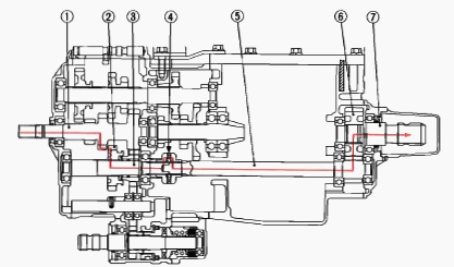
1 - 2nd Gear Shaft with 13T, 13T and 18T Gear, 2 - 17T Shifter Gear, 3 -
3rd Shaft, 4 - One-way Clutch, 5 - 5th Gear Shaft with 11T Gear, 6 - 24T
Gear, 7 - Rear-PTO Shaft
Rear-PTO Shift Lever ON position
2nd Gear Shaft with 13T Gear (1) - 17T Shifter Gear (2) - 3rd Shaft (3)
- One-way Clutch (4) - 5th Gear Shaft with 11T Gear (5) - 24T Gear (6) -
Rear PTO Shaft (7)
Mid-PTO Section
Besides neutral, one kind of power flow are available by operating the
PTO shift lever to shift positions of shifter (5) or 11T shifter gear
(7) for mid-PTO.
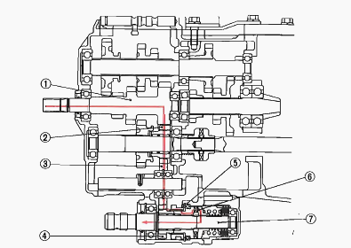
1 - 2nd Gear Shaft with 13T, 13T and 18T Gear, 2 - 13T Gear, 3 - 19T
Gear, 4 - 11T Gear, 5 - Shifter, 6 - One-way Clutch, 7 - Mid-PTO Shaft
Mid-PTO Shift Lever ON Position
2nd Gear Shaft with 18T Gear (1) - 13T Gear (2) - Clutch (6) - Mid-PTO
Shaft (7) 19T Gear (3) - 11T Gear (4) - Shifter (5) - One-way Clutch
One-way Clutch Cam Section
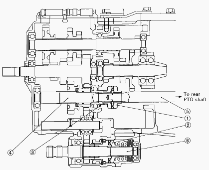
1 - Clutch Cam for Rear PTO, 2 - Clutch Cam for Mid-PTO, 3 - Clutch Cam
Spring, 4 - 3rd Shaft, 5 - 5th Gear Shaft, 6 - Mid-PTO Shaft
The one-way clutch cam is also called an overrunning clutch. It is
composed of a pair of clutch cams (7), (8) and a cam spring (3). One of
the clutch cam is splined to the shaft (6), and the other is splined to
the shaft (5). These two clutch cams (1), (2) are engaged with each
other by the force of the cam spring. As long as the shaft (4) is
rotating faster than the shaft (5), (6) these two clutch cams (7), (8)
will remain engaged, and the shaft (5), (6) is driven. But, if the PTO
shaft drives a rotary mower as an implement, for example, and the source
of power is stopped by pressing the clutch pedal, or if the engine speed
is lowered, the clutch cam (7) will overrun as shown in the figure. This
overrunning is caused by the inertia of the mower blades. Then,
engagement will not take place until the shaft (4) is running faster
than the shaft (5), (6). In this way, the one-way clutch cam protects
the transmission and engine power train against damage, by allowing the
PTO shaft and the shaft (5), (6) to overrun if PTO shaft over speeds.
Kubota B1700, B2400 - Differential Gear
Differential Function
During Straight Running - Rotation of the spiral bevel pinion is
transmitted to the spiral bevel gear and differential case. When road
resistance to the right and left wheels are equal, differential pinions
and differential side gears are all rotate as a unit. Both rear axles
received equal input, and both wheels turn at the same speed, allowing
the tractor to go straight ahead. At this time, differential pinions do
not rotate around the differential pinion shaft.
During Turning - When the tractor turns, the road resistance to the
inside tire increases (as if braking is applied to that side only). In
other words, if one of tires slows down, revolution difference is
generated in the differential side gears. When rotation of one
differential side gear becomes lower than the other, differential
pinions begin rotating around differential increased in speed by the
speed increment of differential pinion rotating around differential
pinion shaft. This means that rotation of one rear axle is slowed down
and that of the other rear axle is increased. Thus, the tractor turn
smoothly without power loss. The combined number of revolutions of the
right and left differential side gears is always twice that of the
spiral bevel gear. When spiral bevel gear revolution is 100 rpm, and if
one of the differential side gears stops moving, the revolution of the
other differential side gear becomes 200 rpm and if one rotates at 50
rpm, the other rotates at 150 rpm.
Kubota B1700, B2400 Differential Lock
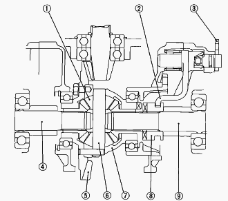
1 - Differential Pinions, 2 - Shift Fork, 3 - Differential Lock Lever, 4
- Differential Gear Shaft, 5 - Spiral Bevel Gear, 6 - Differential
Pinion Shaft, 7 - Differential Case, 8 - Differential Lock Clutch, 9-
Differential Gear Shaft
When resistance to the right and left tires are greatly different due to
ground conditions or type of work, the tire with less resistance slips
and prevents the tractor from moving ahead. To compensate for this
drawback, the differential lock restricts the differential action and
causes both rear axles to rotate as a unit. When the differential lock
pedal is stepped on, it causes the differential lock lever (3) to
rotate, which will move the shift fork (2) and the differential lock
clutch (8) toward the spiral bevel gear (5). The differential lock
clutch (8) engaged with the teeth of the differential case (7) to cause
the differential case (7) and the differential lock clutch (8) to rotate
as a unit. Therefore, differential pinions (1) are unable to rotate
around differential pinion shaft (6) and identical revolutions are
transmitted to the right and left differential gear shafts (4), (9).
Kubota B1700, B2400 - Transmission Case
Separating Hydraulic Cylinder and Rear Axle Case
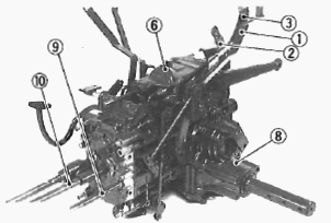
1 - Rear-PTO Shift Lever, 2 - Aux. Speed Change Lever, 3 - Mid-PTO Shift
Lever, 4 - Connecting Plate, 5 - Top Link Bracket, 6 - Hydraulic
Cylinder Assembly, 7 - Drawbar Frame, 8 - Rear Axle Case, 9 - Connecting
Pipe, 10 - Propeller Shaft, 11 - Universal Joint
Remove the connecting pipe (9) and propeller shaft (10). Tap out the
spring pins and remove the universal joint with front wheel propeller
shaft. Remove the external snap ring and remove the auxiliary speed
change lever (2) with rod, rear-PTO shift lever (1) and mid-PTO shift
lever (3). Remove the hook and connecting plate (4). Remove the top link
bracket. Remove the hydraulic cylinder mounting screws and dismount the
hydraulic cylinder assembly (6). Disconnect the differential lock rod.
Remove the drawbar frame mounting screws and remove the drawbar frame.
Remove the rear axle mounting screws and remove the rear axle case (8)
from the differential case. Apply liquid gasket to joint face of the
differential case and the rear axle case, differential case and the
hydraulic cylinder.
Separating Main Shift Cover, Mid-PTO Case and Transmission Case
Remove the main shift cover mounting screws and separate the main shift
cover with differential lock pedal. Remove the mid-PTO case mounting
screws and separate the mid-PTO case from transmission case. Remove the
rear-PTO cover mounting screws and separate the rear-PTO cover (couldn't
draw out completely). Remove the transmission case mounting screws and
nuts and separate the transmission case from differential case. Apply
liquid gasket to joint face of the main shift cover, transmission case,
differential case and mid-PTO case.
Front Cover
Remove the front cover mounting screws and remove the front cover. Apply
liquid gasket to joint face of the front cover and transmission case.
4th Gear Shaft
Remove the bearing, 30T shifter gear and 13T-17T shifter gear. Draw out
the 4th gear shaft with 19T gear rearward.
Spiral Bevel Pinion Shaft and 20T Shifter Gear
Remove the external snap ring and one-way clutch cam. Remove the spiral
bevel pinion shaft with 13T-32T shifter gear, 13T gear, and shift fork
with shift rod. Remove the external snap ring and remove the 20T shifter
gear. When installing the spiral bevel pinion shaft, be sure to install
the shim.
2nd Gear Shaft and Front Wheel Drive Shaft
Remove the 2nd gear shaft with bearing. Draw out the front wheel drive
shaft with 16T-20T gear. When installing the needle bearing into the
16T-20T gear, apply transmission oil to the needle bearings.
Middle Shaft and 3rd Shaft
Tap out the middle shaft and remove the 19T gear with bearing. Draw out
the 3rd shaft with 17T gear, 13T gear and shift fork with shift rod.
When assembling the 19T gear, face the chamfer side to the rear. When
installing the needle bearings into the 13T gear, apply transmission oil
to the needle bearings.
Mid-PTO Shaft and One-way Clutch
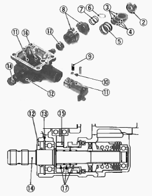
1 - Mid-PTO Case Rear Cover, 2 - Bearing, 3 - Friction Plate, 4 - Brake
Disc, 5 - Spring, 6 - External Snap Ring, 7 - Spring, 8 - One-way Clutch
Cam, 9 - Spring, 10 - Ball, 11 - Shift Arm, 12 - Oil Seal, 13 - Internal
Snap Ring, 14 - Mid-PTO Shaft, 15 - 11T Gear, 16 - Shifter, 17 - Needle
Bearing
Remove the mid-PTO case rear cover mounting screws and separate the rear
cover (1). Remove the bearing (2) and remove the friction plates (3),
brake discs (4) and spring (5). Remove the external snap ring (6) and
remove the spring (7) and one-way clutch cam (8). Remove the spring (9)
and ball (10). Draw out the dowel pin and remove the shift arm (11) with
shifter. Remove the oil seal (12) and internal snap ring (13). Remove
the mid-PTO shaft (14) with bearing, 11T gear (15) and shifter (16).
Apply grease to lip and outer of oil seal. When installing the needle
bearings (17) into the 11T gear and one-way clutch cam, apply
transmission oil to the needle bearings.
Main Gear Shift Fork
Remove the cotter pin and remove the spring and ball. Draw out the shift
rod and remove the 1st-reverse gear shift fork. Remove the 2nd-3rd gear
shift fork, in the same way as the 1st-reverse shift fork removing
procedure. Take out the interlocker and slide the shift arm stopper and
then remove the shim arm. Remove the shift shaft. When remove the
differential lock pedal shaft draw out the dowel pin first.
Kubota B1700, B2400 Tractor - Transmission Case Servicing
Bearing Checking
While holding the inner race, push and pull the outer race in all
directions to check for wear and roughness. Apply transmission oil to
the bearing and hold the inner race. For needle bearing, lay the needle
rollers to check for any damage and wear. Replace it if defects are
found.
Clearance Between Shift Fork and Shift Gear Groove
Insert the fork into the shift gear groove and measure the clearance
with a feeler gauge. If the clearance exceeds the allowable limit,
replace it. Clearance between shift fork and shift gear groove
(Allowable limit) - 0.5 mm (0.020 in).
Clearance between Gear and Shaft
Measure the gear I.D. with a cylinder gauge, and then shaft O.D. with an
outside micrometer. Measure the O.D. of two needles in the needle
bearing with an outside micrometer. Clearance is the difference between
the gear I.D. and the sum of shaft O.D. and two needles O.D. If the
clearance exceeds the allowable limit, replace it. Clearance between FWD
shaft and 16T-20T gear - 0.027 to 0.067 mm (0.0011 to 0.0025 in). FWD
shaft O.D. - 21.967 to 21.980 mm (0.8648 to 0.8654 in). 16T-20T gear
I.D. - 28.007 to 28.021 mm (1.1024 to 1.1032 in). Needle O.D. - 2.996 to
3.000 mm (0.1179 to 0.1181 in). Clearance between 13T gear and 3rd shaft
- 0.007 to 0.046 mm (0.0003 to 0.0018 in). 3rd shaft O.D. - 21.987 to
22.000 mm (0.8656 to 0.8661 in). 13T gear I.D. - 28.00 to 28.021 mm
(1.1026 to 1.1032 in). Needle O.D. - 2.994 to 3.000 mm (0.1179 to 0.1181
in). Clearance between 11T gear, one-way clutch cam and mid-PTO shaft -
0.020 to 0.026 mm (0.0008 to 0.0010 in). Mid-PTO shaft O.D. - 19.989 to
20.000 mm (0.7869 to 0.7874 in). 11T gear and one-way clutch I.D. -
24.007 to 24.020 mm (0.9452 to 0.9457 in). Needle O.D. - 1.997 to 2.000
mm (0.0786 to 0.0787 in).
________________________________________________________________________________
________________________________________________________________________________________
________________________________________________________________________________________
| KUBOTA TRACTORS SPECIFICATIONS |
________________________________________________________________________________________
________________________________________________________________________________________
________________________________________________________________________________________
________________________________________________________________________________________
________________________________________________________________________________________
________________________________________________________________________________________
________________________________________________________________________________________
________________________________________________________________________________________
________________________________________________________________________________________
________________________________________________________________________________________
________________________________________________________________________________________
________________________________________________________________________________________
________________________________________________________________________________________
________________________________________________________________________________________
________________________________________________________________________________________
| KUBOTA ENGINES DATA AND SERVICE SPECS |
________________________________________________________________________________________
________________________________________________________________________________________
________________________________________________________________________________________
________________________________________________________________________________________
________________________________________________________________________________________
| KUBOTA FRONT END LOADERS |
________________________________________________________________________________________
________________________________________________________________________________________
________________________________________________________________________________________
________________________________________________________________________________________
________________________________________________________________________________________
________________________________________________________________________________________
________________________________________________________________________________________
________________________________________________________________________________________
________________________________________________________________________________________
________________________________________________________________________________________
________________________________________________________________________________________
________________________________________________________________________________________
| KUBOTA TRACTORS TROUBLESHOOTING | ||||
| L235 | L2501 | L2550 | L275 | L3110 |
| L3301 | L35 | L3710 | L3901 | L4310 |
| L5030 | M4700 | M5700 | M6040 | M6800 |
| M8200 | M8540 | M9000 | MX5100 | MX5200 |

 SPECIFICATIONS
 LOADERS
 ENGINES
 MAINTENANCE
 PROBLEMS
 B1241
B1241 B1600
B1600 B1700
B1700 B1750
B1750 B21 Backhoe
 B2150
B2150 B2301
B2301 B2320
B2320 B2530
B2530 B26 Backhoe
 B2601
B2601 B2650HSD
 B3030
B3030 B3350
B3350 B6000
B6000 B6100
B6100 B6200
B6200 B7000
B7000 B7001
B7001 B7100HST
 B7200
B7200 B7500
B7500 B7510
B7510 B7800
B7800 B8200HST
 BX1880
 BX2200
 BX2230
 BX2350
 BX2370
 BX23S
BX23S BX25 TLB
 BX2660
 BX2680
 F3680
F3680 L175
L175 L185
L185 L210
L210 L225
L225 L235
L235 L245
L245 L260
L260 L275
L275 L285
L285 L305
L305 GR2120
 L1501
L1501 L2350
L2350 L2550
L2550 L2800
L2800 L3010
L3010 L3200HST
 L3301
L3301 L3560
L3560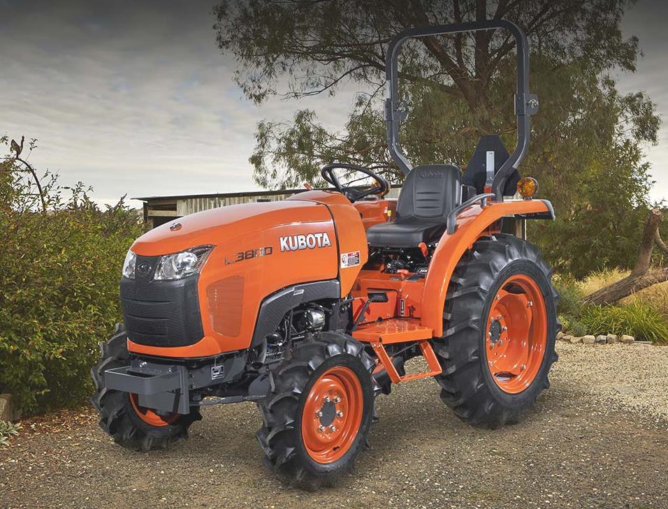 L3800
L3800 L4701
L4701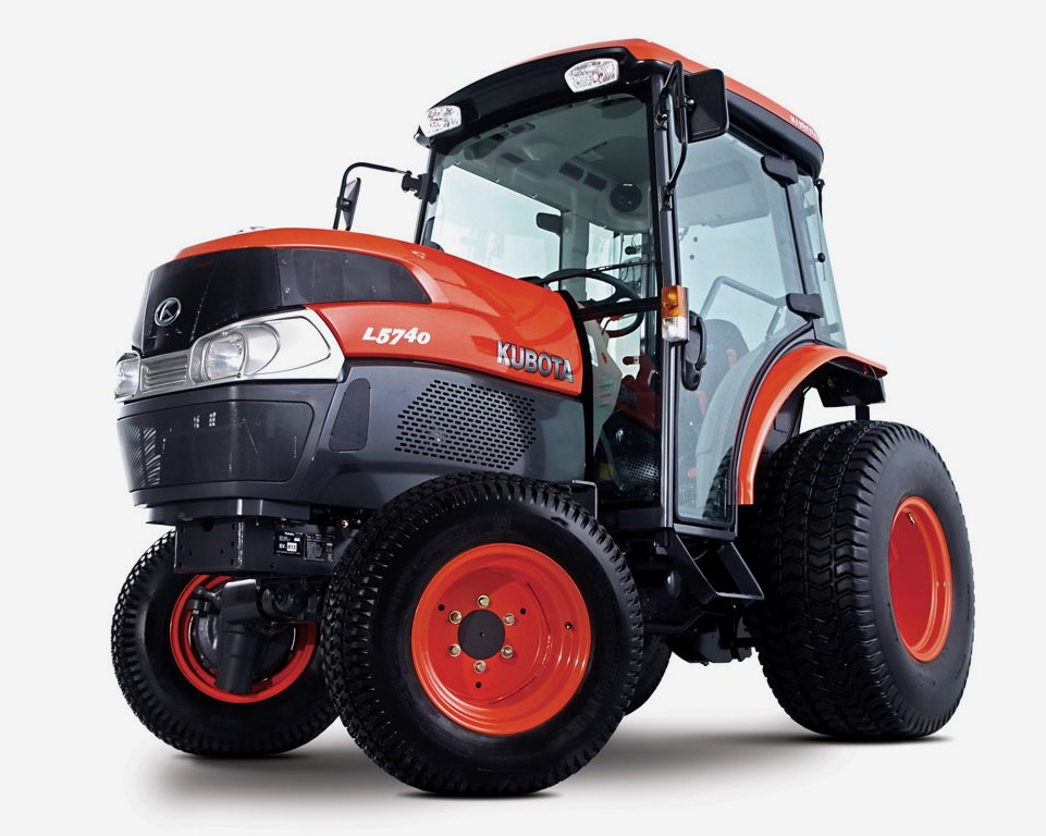 L5740
L5740 M5-091
 M5-111
 M6060
M6060 M7040
M7040 M9540
M9540 M9960
M9960 MX5100
 D662
D662 D722
D722 D750
D750 D782
D782 D850
D850 D902
D902 D905
D905 D950
D950 D1005
D1005 D1100
D1100 D1105
D1105 D1503
D1503 D1703
D1703 D1803
D1803 V1200
V1200 V1205
V1205 V1305
V1305 V1505
V1505 V2203
V2203 V2403
V2403 Z482
Z482 Z602
Z602 Z750
Z750 Z1100
Z1100 Z1300
Z1300 B1630
B1630 BF400
BF400 BF400G
 LA181
LA181 LA203
LA203 LA211
LA211 LA243
LA243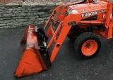 LA271
LA271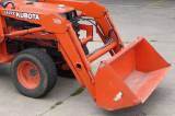 LA272
LA272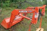 LA301
LA301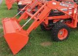 LA302
LA302 LA304
LA304 LA340
LA340 LA344
LA344 LA351
LA351 LA352
LA352 LA364
LA364 LA401
LA401 LA402
LA402 LA434
LA434 LA463
LA463 LA481
LA481 LA482
LA482 LA504
LA504 LA513
LA513 LA514
LA514 LA524
LA524 LA525
LA525 LA534
LA534 LA555
LA555 LA680
LA680 LA681
LA681 LA682
LA682 LA703
LA703 LA714
LA714 LA723
LA723 LA724
LA724 LA764
LA764 LA765
LA765 LA805
LA805 LA844
LA844 LA852
LA852 LA853
LA853 LA854
LA854 LA1002
 LA1055
 LA1065
 LA1153
 LA1154
 LA1251
 LA1301S
 LA1353
 LA1403
 LA1601S
 LA1854
 LA1944
 LA1953
 LA2253
 LM2605