________________________________________________________________________________
Kubota B2050, B2350, B2650 - Transmission
Kubota B2050, B2350, B2650 - Manual
Transmission
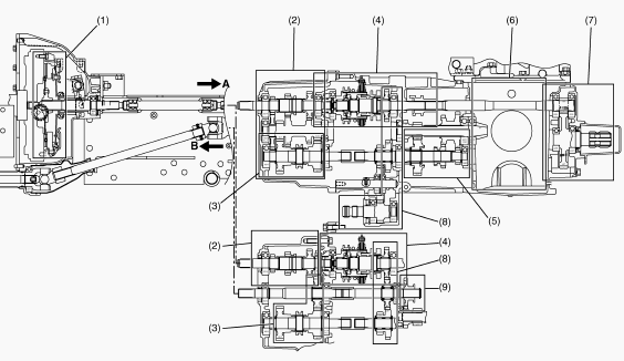
Manual Transmission (without Bi-Speed Turn Model): 1 - Main Clutch
Section, 2 - Main Gear Shift Section, 3 - Shuttle Shift Section, 4 -
Mechanical PTO Clutch Section, 5 - Range Gear Shift Section, 6 -
Differential Gear Section, 7 - Rear PTO Gear Section, 8 - Mid-PTO Gear
Section, 9 - Front Wheel Drive Gear Section, A - From Front Case, B - To
Front Axle
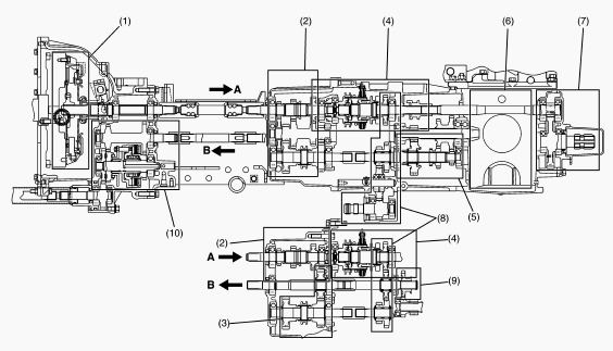
Manual Transmission (with Bi-Speed Turn Model): 1 - Main Clutch Section,
2 - Main Gear Shift Section, 3 - Shuttle Shift Section, 4 - Mechanical
PTO Clutch Section, 5 - Range Gear Shift Section, 6 - Differential Gear
Section, 7 - Rear PTO Gear Section, 8 - Mid-PTO Gear Section, 9 - Front
Wheel Drive Gear Section, 10 - Bi-Speed Turn Gear Section, A - From
Front Case, B - To Bi-Speed Turn Gear Section
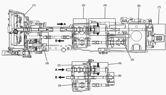
Manual Transmission (with Bi-Speed Turn and without Mid-PTO Model): 1 -
Main Clutch Section, 2 - Main Gear Shift Section, 3 - Shuttle Shift
Section, 4 - Mechanical PTO Clutch Section, 5 - Range Gear Shift
Section, 6 - Differential Gear Section, 7 - Rear PTO Gear Section, 8 -
Front Wheel Drive Gear Section, 9 - Bi-Speed Turn Gear Section, A - From
Front Case, B - To Bi-Speed Turn Gear Section
Main Gear Shift Section
Main shift section consists of three speeds.
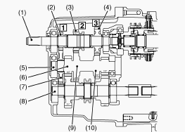
1 - First Shift Shaft, 2 - 13T F1 Gear, 3 - 23T F2 Gear (Shifter), 4 -
29T F3 Gear, 5 - 15T-32T-26T-13T Shaft, 6 - 15T Gear, 7 - 30T F1 Gear, 8
- Shuttle Shaft, 9 - 32T Gear, 10 - 26T Gear
1st Speed Gear - The 23T F2 gear (shifter) (3) slides to the engine
side. The 23T F2 gear (shifter) (3) meshes to the 13T F1 gear (2). The
power is transmitted as follows. First shift shaft (1) - 23T F2 gear
(shifter) (3) - 13T F1 gear (2) - 30T F1 gear (7) - 15T-32T-26T-13T
shaft (5).
2nd Speed Gear - The 23T F2 gear (shifter) (3) meshes to the 32T gear
(9) of the 15T-32T-26T-13T shaft (5). The power is transmitted as
follows. First shift shaft (1) - 23T F2 gear (shifter) (3) - 32T gear
(9) / 15T-32T-26T-13T shaft (5).
3rd Speed Gear - The 23T F2 gear (shifter) (3) slides to the mechanical
PTO clutch side. The 23T F2 gear (shifter) (3) meshes to the 29T F3 gear
(4). The power is transmitted as follows. First shift shaft (1) - 23T F2
gear (shifter) (3) - 29T F3 gear (4) - 26T gear (10) / 15T-32T-26T-13T
shaft (5).
Shuttle Gear Shift Section
The power shifted in the main gear shift section is transmitted from the
15T-32T-26T-13T shaft (2) to the shuttle shaft (3). The shuttle shift
gears are the sliding mesh gears. The reverse shaft is the front wheel
drive shaft (8). The 27T gear (9) on the front wheel drive gear (8) is a
reverse gear.
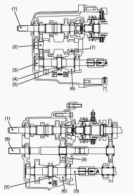
1 - First Shift Shaft, 2 - 15T-32T-26T-13T Shaft, 3 - Shuttle Shaft, 4 -
28T Gear, 5 - Shifter, 6 - 24T Gear, 7 - 13T Gear, 8 - Front Wheel Drive
Shaft, 9 - 27T Gear, F - Forward, R - Reverse, A - To High-Low Range
Gear Section
Forward - When shifting the shuttle lever to “Forward”, the shifter (5)
slides to the 28T gear side. The shifter (5) meshes to the 28T gear (4).
The power is transmitted as follows. 15T-32T-26T-13T shaft (2) / 15T
gear (2) - 28T gear (4) - shifter (5) - shuttle shaft - Hi-Low range
gear section.
Reverse - When shifting the shuttle lever to “Reverse”, the shifter (5)
slides to the 24T gear side. The shifter is transmitted as follows.
15T-32T-26T-13T shaft (2) / 13T gear (7) - 27T gear (9) on the front
wheel drive shaft (8) - 24T gear (6) - shifter (5) - shuttle shaft (3) -
High-low range gear section.
Range gear shift section
Range gear shift lever (1) is located at left side fender. Range gear
shift lever (1) can select three speed range, low speed, mid speed and
high speed. Range gear shift lever (1) and 18T shifter gear (10) are
linked with range shift arm (3) and range shift fork (2) etc. Three
range gear shifts are selected by shifting the 18T shifter gear (10) on
the sub shaft (8) to 17T gear (6) and 25T-31T gear (7) on 6T bevel
pinion shaft (4).
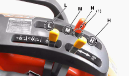
1 - Range Gear Shift Lever, 2 - Range Shift Fork, 3 - Range Shift Arm, 4
- 6T Bevel Pinion Shaft, 5 - 13T Gear (for Front Wheel Drive), 6 - 17T
Gear, 7 - 25T-31T Gear, 8 - Sub Shaft, 9 - 26T Gear, 10 - 18T Shifter
Gear, 11 - 12T Gear, L - LOW Range, M - MID Range, N - Neutral Position,
H - HIGH Range
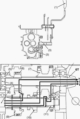
Low Speed Position - Sub shaft (8) - 18T shifter gear (10) - 12T gear
(11) - 31T of 25T-31T gear (7) - 6T bevel pinion shaft (4).
Middle Speed Position - Sub shaft (8) - 18T shifter gear (10) - 25T of
25T-31T gear (7) - 6T bevel pinion shaft (4).
High Speed Position - Sub shaft (8) - 18T shifter gear (10) - 26T gear
(9) - 17T gear (6) - 6T bevel pinion shaft (4).
Kubota B2050, B2350, B2650 Tractor - Power Take Off
Mechanical PTO Clutch
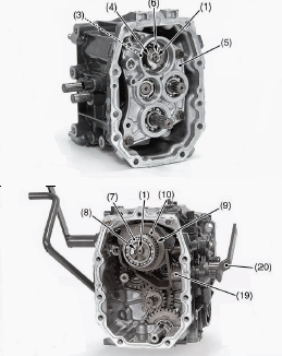
The PTO shift lever (1) is located at left side fender. The PTO
positions are selected to three positions, the “Rear PTO” position (R),
the “Rear PTO/ the mid-PTO” position (R/M) and the “Mid-PTO” position
(M). The PTO section is separated to two sections. The front PTO section
is located in the main speed shift case. The rear PTO is the mechanism
PTO assembly and is located in the transmission case. The shifter (17)
is connected mechanically to the PTO select lever. When the mechanical
PTO clutch lever is shifted to “ON (Engaged)” position, the mechanical
PTO clutch lever sides front and meshes to the one-way clutch spline
boss (21). Since the PTO brake spline boss (12), the power is
transmitted from the one-way clutch spline boss through the shifter (10)
to the PTO brake spline boss (12).
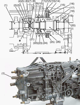
1 - First Shift Shaft, 2 - Collar (1.8), 3 - Overrunning Clutch Spring,
4 - One-way Clutch Cam, 5 - Bearing Holder, 6 - Cir-clip, 7 - Ball
Bearing, 8 - Cir-clip, 9 - One-way Clutch Spline Boss, 10 - Shifter (PTO
ON/OFF), 11 - PTO Brake Spring, 12 - PTO Brake Spline Boss, 13 - Brake
Plate 2, 14 - Brake Disk, 15 - Brake Plate 3, 16 - Brake Plate 1, 17 -
PTO Shifter, 18-25T Mid-gear, 19 - Collar (20), 20 - Ball Bearing, 21 -
Needle Bearing, 22 - Thrust Ball Bearing, 23 - Cir-clip, 24 - Thrust
Collar, 25 - Needle Bearing, 26 - Cir-clip, 27 - PTO Clutch, 28 - PTO
Shift Lever, 29 - PTO ON/OFF Shift Folk, a - One-way Clutch Section, A -
Connected to the PTO Select Lever, R - REAR PTO position, R/M - REAR PTO
/ MID PTO position, M - MID-PTO Position
PTO Brakes
When the mechanical PTO clutch lever is shifted to “OFF (Disengaged)”
position, the shifter slides to the PTO brake spring side. The shifter
does not mesh to the one-way clutch spline boss, and the power is not
transmitted from the one-way clutch spline boss (9) to the PTO brake
spline boss. Since the PTO brake spring pushed the brake prates and the
PTO brake disks, the PTO brake is engaged at this moment.
Kubota B2050, B2350, B2650 Tractor - Rear PTO
When the PTO shift lever is set to “Rear PTO” position (R), the PTO
shifter slides to “Rear PTO” position (R). The PTO shifter meshes to the
spline of the PTO clutch shaft. The power is transmitted from the first
shift shaft to the PTO clutch shaft as follows. First shift shaft -
One-way clutch cam - One-way clutch spline boss - shifter (PTO ON/OFF) -
PTO brake spline boss - PTO shifter - PTO clutch shaft.
Rear PTO / Mid PTO
When the PTO shift lever is set to “Rear PTO/Mid-PTO” position, the PTO
shifter slides to “Rear PTO/Mid-PTO” position (R/M). The PTO shifter
meshes to both the spline of the PTO clutch shaft and the spline of the
25T mid-PTO gear. The power is transmitted from the first shift shaft to
both the rear PTO and the mid-PTO as follows. To Rear PTO: First shift
shaft - One-way clutch cam - One-way clutch spline boss - shifter (PTO
ON/OFF) - PTO brake spline boss - PTO shifter - PTO clutch shaft - to
rear PTO. To Mid PTO: First shift shaft - One-way clutch cam - One-way
clutch spline boss - shifter (PTO ON/OFF) - PTO brake spline boss - PTO
shifter - 25T mid-gear - 26T gear - to mid-PTO.
Mid PTO
When the PTO shift lever is set to “Mid-PTO” position, the PTO shifter
slides to “Mid-PTO” position (M). The PTO shifter meshes to the spline
of the 25T mid-gear. The power is transmitted from the first shift shaft
to the mid-PTO.
Kubota B2050, B2350, B2650 - Clutch
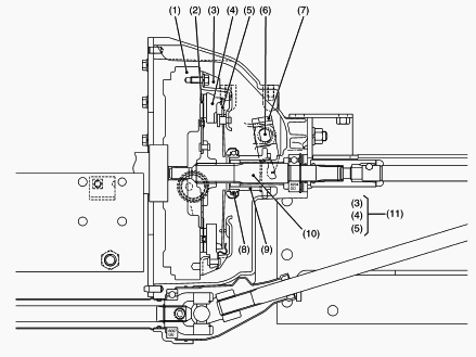
1 - Engine Flywheel, 2 - Clutch Disc, 3 - Clutch Cover, 4 - Pressure
Plate, 5 - Diaphragm Spring, 6 - Clutch Rod, 7 - Clutch Release Fork, 8
- Clutch Release Bearing, 9 - Clutch Release Hub, 10 - Clutch Shaft, 11
- Pressure Plate Assembly
Kubota B2050, B2350, B2650 - Transmission Service
Bi-Speed Turn Clutch
Clutch Disk and Clutch Plate -
Measure the clutch disk thickness with a Vernier calipers. Measure the
clutch plate thickness with a Vernier calipers. If the thickness is less
than the allowable limit, replace it. If the bearing is worn, replace
it. Bi-Speed Turn clutch disk thickness - 1.70 to 1.90 mm (0.067 to
0.075 in). Bi-Speed Turn clutch disk plate thickness - 1.95 to 2.05 mm
(0.0768 to 0.0807 in).
Mechanical PTO Clutch
PTO Clutch Shaft -
Check the needle bearings. Check the needle bearing surfaces of the PTO
clutch shaft. Check the needle bearing surfaces of the one-way clutch
spline boss, the PTO brake spline boss and the 25T mid-PTO gear. If the
PTO clutch shaft is rough or grooved, replace it. If the needle bearing
is wore, replace it. The one-way clutch spline boss, the PTO brake
spline boss or the 25T mid-PTO gear is worn, replace it.
PTO Brake Disk and Brake Plate 1
Measure the PTO brake disk thickness with a Vernier calipers. Measure
the brake plate thickness with a Vernier calipers. If the thickness is
less than the allowable limit, replace it. PTO brake disk thickness -
1.70 to 1.90 mm (0.067 to 0.075 in). Mechanical PTO brake plate 1
thickness - 1.95 to 2.05 mm (0.0768 to 0.0807 in).
Kubota B2050, B2350, B2650 - Mechanical PTO Clutch Assembly
Separating Transmission Case from Differential Case
Remove the transmission mounting bolts and nuts. Separate the
transmission case from the differential case. Install the coupling to
the mechanical PTO clutch shaft. Apply the liquid gasket. Tighten the
transmission mounting bolts and the nuts to the specified torque.
Removing One-Way Clutch Spline Boss
Remove the circlip from the PTO clutch shaft. Remove the one-way clutch
spline boss with the bearing. Remove the needle bearing and the thrust
ball bearing.
Removing PTO ON-OFF Shift Fork and PTO Shift Arm
Remove the circlip from the PTO clutch shaft. Remove the circlip the PTO
ON-OFF arm shaft. Remove the shifter and the PTO clutch spring. Remove
the bolt and the washer from the transmission case. Remove the PTO shift
arm. Install the PTO cotter to the groove of the PTO shifter securely.
Install the ball and the spring to the transmission case using the
special ball guide.
Removing and Disassembling Mechanical PTO Clutch Assembly
Remove the rear PTO shifter from the PTO clutch shaft. Disassemble the
mechanical PTO clutch assembly. Check the mechanical PTO clutch assembly
parts the damage and wear, replace it.
Kubota B2050, B2350, B2650 Tractor - Separating Engine From Clutch housing
Draining Transmission Fluid
Place oil pan underneath the transmission case, and remove the drain
plugs. Drain the transmission fluid. Reinstall the drain plug. Fill new
oil from port after remaining the filling plug up to the upper notch on
the dipstick. After running the engine for new minutes, stop it and
check the oil level again, it low, add oil prescribed level.
Transmission fluid capacity -
Manual transmission (without Bi-Speed Turn) - 15 L. Manual transmission
(with Bi-Speed Turn) - 16.5 L.
Bonnet, Side Cover and Battery Cord
Open the bonnet and remove the front grille. Disconnect the battery
negative cord. Disconnect the head light connectors and remove the
bonnet side covers. When disconnecting the battery cords, disconnect the
grounding cord first. When connecting, positive cord first.
Hydraulic Hoses from Power Steering Cylinder
Disconnect the hydraulic hoses from the power steering cylinder.
Removing the snap pin and disconnect the bi-speed rod.
Fuel -
Disconnect the fuel hose from the fuel filter. Drain the fuel to the
fuel tank completely.
Steering Wheel, Meter Panel, Shuttle Lever and Panel Lower Cover
Remove the steering wheel cap. Remove the steering wheel mounting nut.
Remove the steering wheel with a steering wheel puller. Remove the
accelerator lever grip and the steering boot. Disconnect the hour meter
cable and wiring harness connectors. Remove the meter panel not to
damage with the steering shaft. Remove the shuttle lever. Remove the
panel lower cover.
Fuel Tank
Disconnect the leads from the fuel tank. Disconnect the overflow hoses
from the fuel tank. Remove the shutter plate and the fuel tank.
Key Stop Solenoid and Hydraulic Delivery Pipe
Remove the key stop solenoid connector. Remove the engine stop solenoid
using a small size ratchet handle, the extension joint, the universal
joint and the thinner socket (10 mm). Remove the hydraulic delivery pipe
mounting nuts. Slide the hydraulic delivery pipe. Loosen the hose band.
Disconnect the suction hose from the hydraulic pump. Apply the liquid
gasket to the joint face of the key stop solenoid and the engine.
Steps (4-cylinder Engine, ROPS Model)
Remove the bolts and the nut. Remove the brake spring from the step
(RH). Remove the brake spring and the clutch spring from the step (LH).
Sub-Frames (4-cylinder Engine Model)
Place the rigid jack under the rear axle shaft. Remove the transmission
oil filter cartridge. Loosen the sub-frame mounting bolts. Remove the
sub-frames.
Separating Engine with Front Axle
Reinstall the rear tires. Support the transmission with a disassembling
stand. Hook the engine with a hoist. Place the disassembling stand under
the main frame. Disconnect the power steering hoses. Loose the hydraulic
inlet hose band. Disconnect the hydraulic inlet hose from the hydraulic
pump. Disconnect the hydraulic delivery pipe from the hydraulic pump.
Disconnect the wiring leads from the alternator, the engine oil pressure
switch and the starter motor. Disconnect the wiring harness and the
power steering hoses from the engine body. Remove the docking bolts
between the engine and the front case. Align the spline between the
front wheel drive shaft and the universal joint securely.
Separating the Clutch Assembly
Remove the clutch assembly from the flywheel. Direct the shorter end of
the clutch disc boss toward the flywheel. Apply molybdenum disulphide to
the splines of clutch disc boss. Install the pressure plate, noting the
position of straight pins. Align the center of clutch disc and flywheel
by inserting the clutch center tool. Do not allow grease and oil on the
clutch disc facing.
Clutch and Clutch Release Fork
Remove the external snap ring at the end of clutch rod shaft and remove
the clutch release fork and the release bearing with release bearing
holder.
Set the clutch release fork and the release bearing with the release
folk spring in the correct direction.
________________________________________________________________________________
________________________________________________________________________________________
________________________________________________________________________________________
| KUBOTA TRACTORS SPECIFICATIONS |
________________________________________________________________________________________
________________________________________________________________________________________
________________________________________________________________________________________
________________________________________________________________________________________
________________________________________________________________________________________
________________________________________________________________________________________
________________________________________________________________________________________
________________________________________________________________________________________
________________________________________________________________________________________
________________________________________________________________________________________
________________________________________________________________________________________
________________________________________________________________________________________
________________________________________________________________________________________
________________________________________________________________________________________
________________________________________________________________________________________
| KUBOTA ENGINES DATA AND SERVICE SPECS |
________________________________________________________________________________________
________________________________________________________________________________________
________________________________________________________________________________________
________________________________________________________________________________________
________________________________________________________________________________________
| KUBOTA FRONT END LOADERS |
________________________________________________________________________________________
________________________________________________________________________________________
________________________________________________________________________________________
________________________________________________________________________________________
________________________________________________________________________________________
________________________________________________________________________________________
________________________________________________________________________________________
________________________________________________________________________________________
________________________________________________________________________________________
________________________________________________________________________________________
________________________________________________________________________________________
________________________________________________________________________________________
| KUBOTA TRACTORS TROUBLESHOOTING | ||||
| L235 | L2501 | L2550 | L275 | L3110 |
| L3301 | L35 | L3710 | L3901 | L4310 |
| L5030 | M4700 | M5700 | M6040 | M6800 |
| M8200 | M8540 | M9000 | MX5100 | MX5200 |

 SPECIFICATIONS
 LOADERS
 ENGINES
 MAINTENANCE
 PROBLEMS
 B1241
B1241 B1600
B1600 B1700
B1700 B1750
B1750 B21 Backhoe
 B2150
B2150 B2301
B2301 B2320
B2320 B2530
B2530 B26 Backhoe
 B2601
B2601 B2650HSD
 B3030
B3030 B3350
B3350 B6000
B6000 B6100
B6100 B6200
B6200 B7000
B7000 B7001
B7001 B7100HST
 B7200
B7200 B7500
B7500 B7510
B7510 B7800
B7800 B8200HST
 BX1880
 BX2200
 BX2230
 BX2350
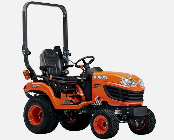 BX2370
 BX23S
BX23S BX25 TLB
 BX2660
 BX2680
 F3680
F3680 L175
L175 L185
L185 L210
L210 L225
L225 L235
L235 L245
L245 L260
L260 L275
L275 L285
L285 L305
L305 GR2120
 L1501
L1501 L2350
L2350 L2550
L2550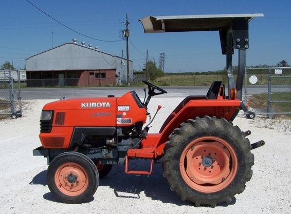 L2800
L2800 L3010
L3010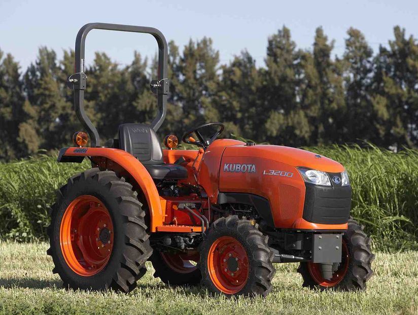 L3200HST
 L3301
L3301 L3560
L3560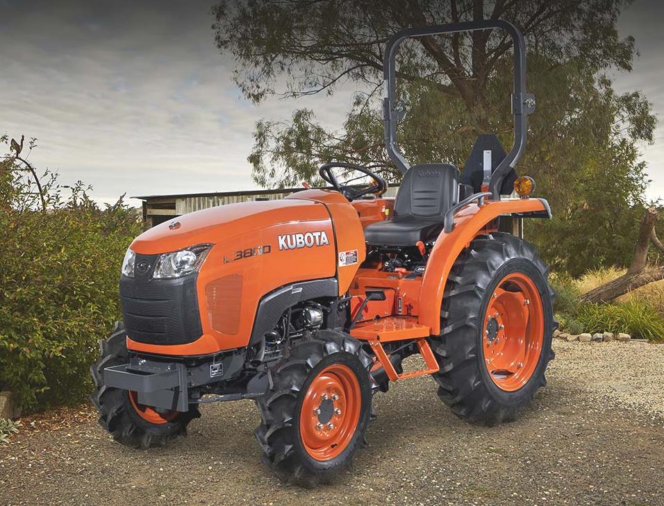 L3800
L3800 L4701
L4701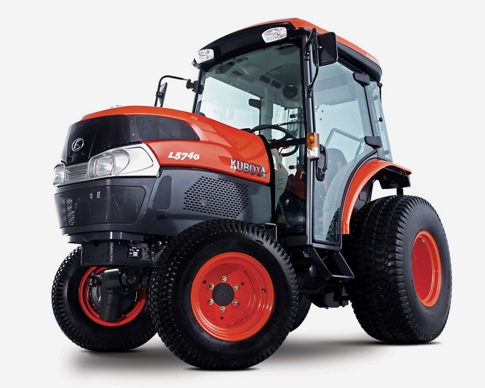 L5740
L5740 M5-091
 M5-111
 M6060
M6060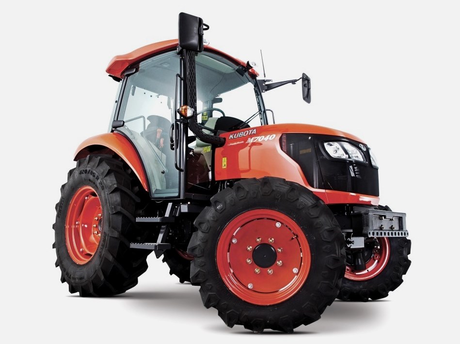 M7040
M7040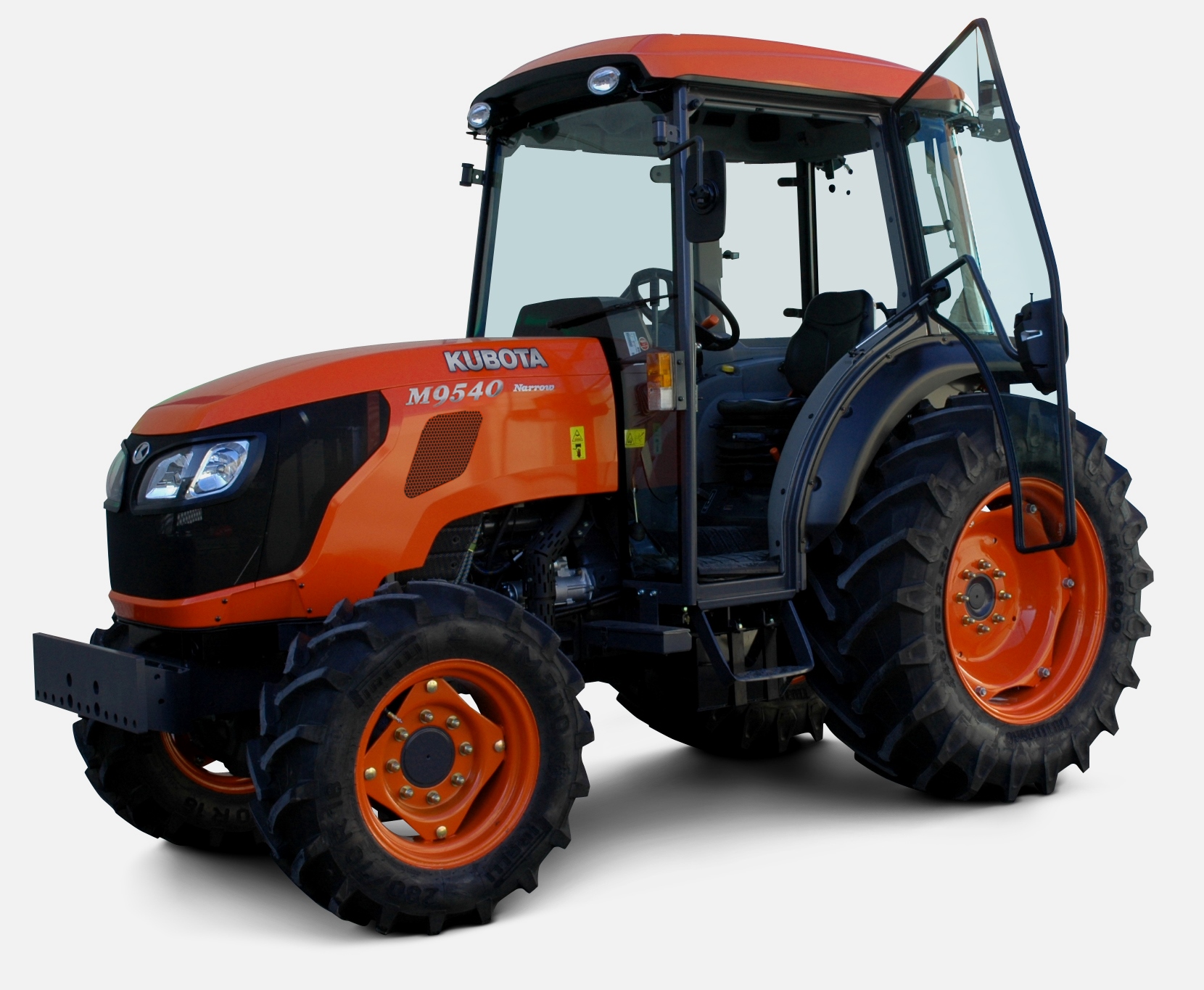 M9540
M9540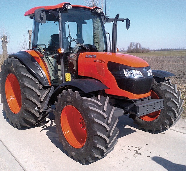 M9960
M9960 MX5100
 D662
D662 D722
D722 D750
D750 D782
D782 D850
D850 D902
D902 D905
D905 D950
D950 D1005
D1005 D1100
D1100 D1105
D1105 D1503
D1503 D1703
D1703 D1803
D1803 V1200
V1200 V1205
V1205 V1305
V1305 V1505
V1505 V2203
V2203 V2403
V2403 Z482
Z482 Z602
Z602 Z750
Z750 Z1100
Z1100 Z1300
Z1300 B1630
B1630 BF400
BF400 BF400G
 LA181
LA181 LA203
LA203 LA211
LA211 LA243
LA243 LA271
LA271 LA272
LA272 LA301
LA301 LA302
LA302 LA304
LA304 LA340
LA340 LA344
LA344 LA351
LA351 LA352
LA352 LA364
LA364 LA401
LA401 LA402
LA402 LA434
LA434 LA463
LA463 LA481
LA481 LA482
LA482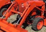 LA504
LA504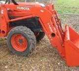 LA513
LA513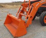 LA514
LA514 LA524
LA524 LA525
LA525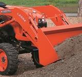 LA534
LA534 LA555
LA555 LA680
LA680 LA681
LA681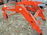 LA682
LA682 LA703
LA703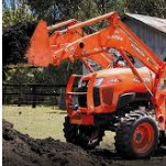 LA714
LA714 LA723
LA723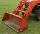 LA724
LA724 LA764
LA764 LA765
LA765 LA805
LA805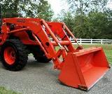 LA844
LA844 LA852
LA852 LA853
LA853 LA854
LA854 LA1002
 LA1055
 LA1065
 LA1153
 LA1154
 LA1251
 LA1301S
 LA1353
 LA1403
 LA1601S
 LA1854
 LA1944
 LA1953
 LA2253
 LM2605