________________________________________________________________________________
Kubota B2100, B21, B7300 - Hydrostatic Transmission
Kubota B21, B2100, B7300 Tractor -
Transmission Components
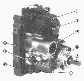
1 - Charge Relief Valve, 2 - Check and High Pressure Relief Valve, 3 -
Trunnion Shaft, 4 - Center Section, 5 - Variable Displacement Piston
Pump, 6 - Charge Pump, 7 - Input Shaft (Pump Shaft), 8 - Housing, 9 -
Fixed Displacement Piston Motor
The hydrostatic transmission consists of a variable displacement piston
pump and a fixed displacement piston motor. Convenient single lever
control permits simple operation of the vehicle, starting, stopping,
increasing or decreasing speeds, changing direction of travel, and even
going up or down hills.
Pump and Motor
Pump and motor cylinder, each containing pistons, are connected by
lines. Cylinders and lines are filled with oil. Pistons ride against
swashplates located in pump and motor. In the pump, as the cylinder
rotates, pistons move across the sloping face of swashplate and slide in
or out of their cylinder bores. The oil, forced out by the pump pistons,
causes the motor pistons to slide out of their cylinder bores. In the
motor, sliding out of the cylinder and moving across the sloping face of
swashplate, the pistons rotate the cylinder.
Oil Flow and Valves
The pump and motor are joined in a closed hydraulic loop and most of oil
circulates within the main oil circuit. A little oil lubricates and
oozes out from the clearance between the moving parts of the case. Then
oil in the main oil circuit of the HST needs to be supplied a want. The
combined oil flow from the power steering circuit and HST charge pump
are flows into the HST for charging. The charge oil aids smooth
operation of piston pump and motor. The charge oil passes through the
oil cooler and transmission oil filter to charge relief valve port. The
rest of oil passes through the charge relief valve into the HST housing.
Oil from the hydraulic cylinder and overflow oil from HST housing return
to the transmission case.
Charge Relief Valve
While pumped and filtered oil flows into the main oil circuit through
the check valves, excessive oil passes to the case through the charge
relief valve.
Check and High Pressure Relief Valve
The check and high pressure relief valves monitor the oil pressure in
each line of the main oil circuit. In neutral, both valves are open and
charging oil enters into the main oil circuit through the valves. At
normal operation, the check valve in the high pressure side is closed
and it pushes and opens the another one. When excessively high pressure
is built up in one line, the high pressure relief valve located in this
line is open and the oil flows into another line.
Control Linkage
The speed control pedal and the trunnion shaft of variable swashplate
are linked with the speed control rod and the trunnion control lever
assembly. As the front footrest of the pedal is depressed, the
swashplate rotates and forward travelling speed increases. Depressing
the rear footrest increases reverse speed. The roller on the trunnion
lever holder with spring seats the detent of the trunnion arm so that
the trunnion lever returns to neutral. Then, the swashplate is returned
to neutral with the trunnion control lever assembly, when the pedal is
released. The damper connected to the speed control pedal restricts the
movement of the linkage to prevent abrupt operation or reversing. The
speed set lever linked to the speed control pedal enables the linkage
not to return to neutral and to keep a certain forward speed while the
speed control pedal is released.
Kubota B2100, B21, B7300 HST - PTO System
Rear-PTO Shift Section
Besides neutral, one kind of power flow are available by operating the
PTO shift lever to shift positions of 17T shifter gear (2) for rear-PTO.
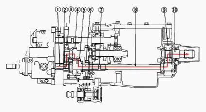
1 - HST Pump Shaft, 2 - 14T Gear, 3 - 27T Gear, 4 - 2nd Gear Shaft with
13T and 18T Gear, 5 - 17T Shifter Gear, 6 - 3rd Shaft, 7 - Coupling, 8 -
5th Shaft with 11T Gear, 9 - 24T Gear, 10 - Rear-PTO Shaft.
Rear-PTO Shift Lever ON position
HST Pump Shaft (1) - 14T Gear (2) - 27T Gear (3) - 2nd Gear Shaft with
13T Gear (4) - 17T Shifter Gear (5) - 3rd Shaft (6) - Coupling (7) - 5th
Shaft with 11T Gear (8) - 24T Gear (9) - Rear-PTO Shaft (10).
Mid-PTO Section
Besides neutral, one kind of power flow are available by operating the
PTO shift lever to shift positions of shifter (5) or 11T shifter gear
(7) for mid-PTO.
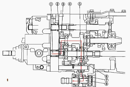
1 - HST Pump Shaft, 2 - 14T Gear, 3 - 27T Gear, 4 - 2nd Gear Shaft with
13T and 18T Gear, 5 - 13T Gear, 6 - 19T Gear, 7 - 11T Shifter Gear, 8 -
Mid-PTO Shaft.
Mid-PTO Shift Lever ON Position
HST Pump Shaft (1) - 14T Gear (2) - 27T Gear (3) - 2nd Gear Shaft with
18T Gear (4) - 13T Gear (5) - 19T Gear (6) - 11T Shifter Gear (7) -
Mid-PTO Shaft (8).
Kubota B21, B2100, B7300 - Clutch
Separating the Clutch Assembly
Remove the clutch assembly from the flywheel. Direct the shorter end of
the clutch disc boss toward the flywheel. Apply molybdenum disulphide to
the splines of clutch disc boss. Install the pressure plate, noting the
position of straight pins. Align the center of clutch disc and flywheel
by inserting the clutch center tool.
Clutch Rod and Clutch Release Fork
Remove the clutch pedal rod. Remove the external snap ring at the end of
clutch rod and remove the clutch release fork and release bearing with
release hub. Set the clutch release fork and release hub with set spring
in the correct direction.
Kubota B21, B2100, B7300 HST - Clutch
Replacement Service
Backlash between Clutch Disc and Clutch Shaft
Mount the clutch disc onto the propeller shaft. Hold the propeller shaft
so that it does not rotate. Slightly move the disc and measure the
displacement around disc edge. If the measurement exceeds the allowable
limit, replace clutch disc. Displacement around disc edge - 2.0 mm
(0.079 in).
Clutch Disc Wear
Measure the depth from clutch disc surface to the top of rivet at least
10 points with a depth gauge. If the depth is less than the allowable
limit, replace. If oil is sticking to the clutch disc, or disc surface
is carbonized, replace clutch disc. Depth to river top - 0.3 mm (0.012
in).
Pressure Plate Flatness
Place a straightedge on the pressure plate and measure clearance with a
feeler gauge at several points. If the clearance exceeds allowable
limit, replace pressure plate. When the pressure plate is worn around
its outside and its inside surface only is in contact with the
straightedge, replace it even if the clearance is within the allowable
limit. Clearance between pressure plate and straightedge - 0.2 mm (0.008
in).
Checking Pressure Plate and Diaphragm
Check the pressure plate and if scratched on its surface, correct with
sandpaper or replace it. Check the diaphragm for cracks and scratches.
If defects are found, replace it.
Checking Clutch Release Bearing
Check the clutch release bearing. If surface is worn excessively, or
abnormal sounds occur, replace it.
Kubota B2100, B21, B7300 Transmission -
Checking And Adjusting
Neutral
Disengage the front wheel drive lever (Drive only rear wheels). Lift the
rear of the tractor so that the rear wheels are off the ground and run
the engine at low idling and drive only rear wheels. Depress the one end
of speed control pedal and release, and do the same at the other end. If
the rear wheels do not stop turning, adjust as following procedure.
Before loosen the neutral adjuster setting screw, be sure to insert the
screw driver to hole of neutral adjuster. This mean prevent to comes out
neutral adjuster at adjusting window.
Adjusting Neutral
Disconnect the brake rod RH. Remove the HST pedal damper. Loosen the
neutral adjuster setting screw. When rear wheels tend to turn forward -
Rotate the neutral adjusting lever clockwise so that the rear wheels
turn reverse. Then rotate it counterclockwise until wheels stop
completely. When rear wheels tend to turn reverse - Rotate the neutral
adjusting lever counterclockwise so that the rear wheels turn forward.
Then rotate it clockwise until wheels stop completely.
Oil Pressure in Hydrostatic Transmission
Clean and clear the work area and fully engage the parking brake.
Measure the following oil pressures using HST adaptors.
Check and High Relief Pressure
Remove the 8 mm (0.31 in.) hex socket head plug from P1 or P2 port (P1
is for forward and P2 is for reverse). Assemble the HST adaptor and
threaded joint with the gasket between them. Install the assembled HST
adaptor and threaded joint to P1 (forward) or P2 (reverse) port. Install
the cable threaded joint in relief valve set pressure tester and high
pressure gauge to threaded joint in order. Run the engine at 2600 rpm.
Place the high-low shift lever in high. Depress the speed control pedal
approx. 10 mm (0.39 in.) which rotates the trunnion shaft 0.087 rad
(5.0°).
Kubota B21, B2100, B7300 - Transmission Case
Disassembly
Charge Pump Housing and Spacer
Remove the charge pump mounting hex. socket head screw, and remove the
charge pump assembly from the HST housing. Remove the charge pump spacer
from the charge pump assembly.
Center Section
Remove the external snap ring and 14T gear. Remove the center section
mounting hex. socket head screw. Lift and remove the center section from
the HST housing. Place a new gasket on the housing. Press the cylinder
block (motor side) by hand then softly reinstall the counter section. Be
careful the pistons for come off from the cylinder block. Install the
snap ring with its rounded edge facing the gear so that its sharp edge
in the groove keep itself in place against the face.
Check and High Pressure Relief Valve
Remove the hex. socket head plug and remove the spring and relief valve
assembly. Take care not to damage the O-ring On the plug.
Cylinder Block Assembly and Thrust Ball Bearing
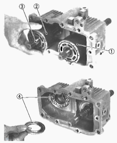
1.Cylinder Block Assembly (Pump Side), 2.Cylinder Block Assembly (Motor
Side), 3.Motor Shaft, 4.Thrust Ball Bearing
Lay the housing on its side. Remove the cylinder block assembly (pump
side) (1). Remove the cylinder block assembly (motor side) (2) with the
motor shaft (3). Remove the thrust ball bearing (4). Apply clean
hydrostatic transmission oil to thrust ball bearing, cylinder block and
piston.
Swashplate
Remove the swashplate from the housing. Remove the thrust plate, thrust
roller bearing and thrust washer from the swashplate. Apply clean
hydrostatic transmission oil to the thrust roller bearing. Place the
swashplate into the housing, align the groove of swashplate and slot
guide by keeping the slot guide from moving with a screw driver.
Slot Guide, Cradle Bearing and Trunnion Arm
Remove the slot guide from the trunnion arm. Remove the cradle bearing
from the housing. Remove the trunnion arm. Remove the oil seal with a
screw driver. Apply clean hydrostatic transmission oil to journal
bearing, trunnion arm and cradle bearing.
Pump Shaft
Remove the internal snap ring. Tap the pump shaft with a plastic hammer
slightly to slide out it from the housing.
Charge Relief Valve
Remove the charge relief valve plug. Remove the spring and charge relief
corn. If shims are placed at the bottom of the relief valve plug bore,
place them as they are. Take care not to damage the a-ring on the relief
plug.
Separating Hydraulic Cylinder and Rear Axle Case
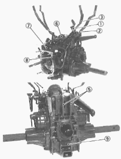
1 - Aux. Speed Change Lever, 2 - Rear-PTO Shift Lever, 3 - Mid-PTO Shift
Lever, 4 - Connecting Plate, 5 - Top Link Bracket, 6 - Hydraulic
Cylinder Assembly, 7 - Differential Lock Pedal Support, 8 - Differential
Lock Pedal, 9 - Drawbar Frame
Remove the external snap ring and remove the auxiliary speed change
lever (1) with rod, rear-PTO shift lever (2) and mid-PTO shift lever
(3). Remove the hook and connecting plate (4). Remove the top link
bracket (5). Remove the hydraulic cylinder mounting screws and dismount
the hydraulic cylinder assembly (6). Disconnect the differential lock
rod and remove the differential lock pedal support (7) with differential
lock pedal (8). Remove the drawbar frame mounting screws and remove the
drawbar frame (9). Apply liquid gasket to joint face of the differential
case and the rear axle case, differential case and the hydraulic
cylinder.
Separating Mid-PTO Case and Transmission Case
Remove the mid-PTO case mounting screws and separate the mid-PTO case
from transmission case. Remove the transmission case mounting screws and
nuts and separate the transmission case from the differential case.
Apply liquid gasket to joint face of the transmission case, differential
case and mid-PTO case.
Bearing Holder
Remove the external snap ring and remove the 27T gear. Remove the
bearing holder mounting screws and remove the bearing holder.
2nd Gear Shaft and 17T Shifter Gear
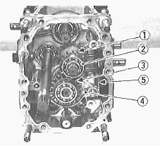
1 - 2nd Gear Shaft, 2 - Bearing, 3 - 17T Shifter Gear, 4 - Shift Fork, 5
- Shift Lever
Remove the 2nd gear shaft (1) with bearings. Remove the bearing (2), 17T
shifter gear (3) and shift fork (4) with shift rod. Remove the shift
lever (5).
Middle Shaft and 3rd Shaft
Tap out the middle shaft and remove the 19T gear with bearing. Draw out
the 3rd shaft with 13T gear. When assembling the 19T gear, face the
chamber side to the rear. When installing the needle bearings into the
13T gear, apply transmission oil to the needle bearings.
Mid-PTO Shaft
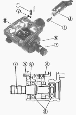
1 - Spring, 2 - Ball, 3 - Shift Arm, 4 - Shifter, 5 - Oil Seal, 6 -
Internal Snap Ring, 7 - Mid-PTO Shaft, 8 - 11T Shifter Gear, 9 - Bearing
Remove the spring (1) and ball (2). Draw out the dowel pi n and remove
the shift arm (3) with shifter (4). Remove the oil seal (5) and internal
snap ring (6). Remove the mid-PTO shaft (7) with 11T shifter gear (8)
and bearings (9). Apply grease to lip and outer of oil seal.
Front Wheel Drive Shaft
Remove the external snap ring and remove the 20T shifter gear. Draw out
the front wheel drive shaft to the front.
4th Gear Shaft and Spiral Bevel Pinion Shaft
Remove the spiral bevel pinion shaft with 15T-29T shifter gear, 13T
gear. Remove the 4th gear shaft with 18T gear. When installing the
spiral bevel pinion shaft, be sure to install the shim.
Kubota B21, B2100, B7300 HST - Transmission
Case Service
Charge Pump
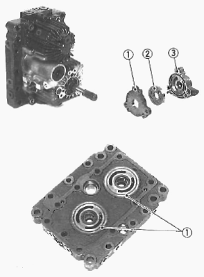
1.Spacer, 2.Gerotor Assembly, 3.Charge Pump Housing
Check the charge pump housing (3), spacer (1) and the gerotor assembly
(2) for scratches and wear. If scratch or worn, replace the charge pump
complete assembly.
Center Section
Check the surface of center section for scratches or wear. If deep
scratch or excessive wear is found, replace the center section.
Check and High Pressure Relief Valve
Check the valve for scratches and damage. Check the valve seat in the
center section for damage. Check the spring for breakage and wear. If
anything unusual, replace the high pressure relief valve complete
assembly.
Cylinder Block Assembly
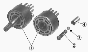
1.Cylinder Block, 2.Spring, 3.Spring Seat, 4.Piston
Check cylinder blocks (1) and pistons (4) for scratches and wear. If
deep scratch or excessive wear is found, replace the cylinder block
assembly. Check that the piston (4), spring (2) and spring seat (3) are
in each cylinder bore. Check the pistons for their free movement in the
cylinder block bores. If the piston or cylinder block bore is scored,
replace the cylinder block assembly.
Thrust Washer, Thrust Roller Bearing and Thrust Plate
Check the thrust roller bearing for scratches and excessive wear. If
worn, replace. Check the thrust plate for scratches and excessive wear.
If worn or scored, replace.
Pump Shaft
Check the seal surface, the bearing surface and the bearing. If the
shaft is rough or groove, replace. If the bearing is worn, replace.
Needle Bearing and Oil Seal
Check the oil seals for damage. Check the needle bearings for wear. If
the oil seals and bearings are worn, replace them.
Charge Relief Valve
Check the charge relief cone and the seat in the housing for damage. If
defects are found, replace them.
Bearing Check
While holding the inner race, push and pull the outer race in all
directions to check for wear and roughness. Apply transmission oil to
the bearing and hold the inner race. For needle bearing, lay the needle
rollers to check for any damage and wear. Replace it if defects are
found.
Clearance between Shift Fork and Shift Gear Groove
Insert the fork into the shift gear groove and measure the clearance
with a feeler gauge. If the clearance exceeds the allowable limit,
replace it. Clearance between shift fork and shift gear groove - 0.10 to
0.35 mm (0.004 to 0.014 in).
Clearance between 13T Gear and 3rd Shaft
Measure the 13T gear I.D. with an inside micrometer, and then 3rd shaft
O.D. with an outside micrometer. Measure the O.D. of two needles in the
needle bearing with an outside micrometer. Clearance is the difference
between the gear I.D. and the sum of shaft O.D. and two needle O.D. If
the clearance exceeds the allowable limit, replace. Clearance between
13T gear and 3rd shaft - 0.007 to 0.046 mm (0.0003 to 0.0018 in). 3rd
shaft O.D. - 21.987 to 22.000 mm (0.8656 to 0.8661 in). 13T gear I.D. -
28.007 to 28.021 mm (1.1026 to 1.1032 in). Needle O.D. - 2.994 to 3.000
mm (0.1179 to 0.1181 in).
Kubota B21, B2100, B7300 - Differential Case
Service
Clearance between Differential Case and Differential Side Gear
Measure the differential side gear boss O.D. with an outside micrometer.
Measure the differential case I.D. and the spiral bevel gear I.D. with
an inside micrometer. If the clearance exceeds the allowable limit,
replace it. Clearance between differential case and differential side
gear - 0.025 to 0.066 mm (0.0016 to 0.0029 in). Differential case I.D. -
32.000 to 32.025 mm (1.2598 to 1.2608 in). Differential side gear O.D. -
31.959 to 31.975 mm (1.2582 to 1.2589 in). Spiral bevel gear I.D. -
32.000 to 32.025 mm (1.2598 to 1.2608 in).
Clearance between Differential Pinion Shaft and Differential Pinion
Measure the differential pinion shaft O.D. with an outside micrometer.
Measure the 'differential pinion I.D. with an inside micrometer. If the
clearance exceeds the allowable limit, replace it. Clearance between
differential pinion shaft and differential pinion 0.016 to 0.045 mm
(0.0006 to 0.0018 in). Differential pinion shaft O.D. - 15.973 to 15.984
mm (0.6289 to 0.6293 in). Differential pinion I.D. - 16.000to 16.018 mm
(0.6299 to 0.6306 in).
Backlash between Differential Pinion and Differential Side Gear
Secure the differential case with a vise. Set the dial indicator (lever
type) with its finger on the tooth of the differential side gear. Press
differential pinion and side gear against the differential case. Hold
the differential pinion and move the differential side, gear to measure
the backlash. If the backlash exceeds the allowable limit, adjust with
differential side gear shims. Backlash between differential pinion and
differential side (Allowable limit) - 0.4mm (0.016 in).
Backlash between Spiral Bevel Pinion and Spiral Bevel Gear
Set the dial indicator (lever type) with its finger on the end of spiral
bevel pinion. Move the spiral bevel pinion back and forth to each end
and measure the side clearance. If the side clearance exceeds the
factory spec., adjust with the shims at front end of spiral bevel
pinion. Set the dial indicator (lever type) with its finger on the tooth
surface of bevel gear. Measure the backlash by fixing the spiral bevel
pinion and moving bevel gear by hand. If the backlash exceeds the
factory spec., adjust with the shims at bearing holder and differential
case. Adjust the backlash properly by repeating the above procedures.
Side clearance of spiral bevel pinion - Less than 0.15 mm (0.006 in).
Backlash between spiral bevel pinion and spiral bevel gear - 0.10 to
0.20mm (0.0039 to 0.0080 in).
Kubota B21, B2100, B7300 Tractor - Rear Axle
The rear axles are the semi floating type with ball bearings (2) between
the rear axle (4) and the rear axle case (3), which supports the rear
wheel load as well as transmitting power to the rear wheels. The
differential (7) automatically controls the revolution of right and left
wheels when the rear wheels encounter unequal road resistance during
turning.
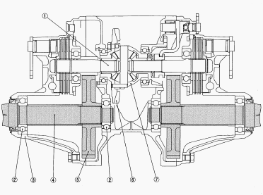
1 - Differential Gear Shaft, 2 - Ball Bearing, 3 - Rear Axle Case, 4 -
Rear Axle, 5 - Spur Gear, 6 - Spiral Bevel Gear, 7 - Differential
Separating Rear Axle Case from Differential Gear Case
Drain the Transmission Fluid
Place oil pans underneath the transmission case. Remove the four drain
plug. Drain the transmission oil. Reinstall the four drain plugs. Fill
up from filling port after removing plug until reaching the gauge. After
running the engine for few minutes, stop it and check the oil level
again. Add the oil to prescribed level if it is not correct level.
Rear Wheel
Place a jack under the transmission case. Loosen the rear wheel cotter
setting bolt and nut. Take out the wheel hub pin. Take out the rear
wheel. When refitting or adjusting a wheel, tighten the bolts to the
following torques then recheck after driving the tractor 200 m (200
yards) and there after daily check service.
Rear Axle Case
Disconnect the differential lock rod. Disconnect the brake rod. Remove
the rear axle case mounting screw. Separate the rear axle case from
differential gear case. Apply liquid gasket to joint face of the rear
axle case and differential gear case after eliminate the water, oil and
stuck liquid gasket.
Separating Hydrostatic Transmission
Tap out the spring pins and remove the universal joint with front wheel
propeller shaft. Remove the neutral adjuster setting screw and loosen
the trunnion control lever mounting bolt and nut. Then remove the
trunnion control lever assembly. Remove the hydrostatic transmission
mounting screws and nuts, and separate the hydrostatic transmission from
the transmission case. When assembling the neutral spring bracket,
adjust the clearance between nut and bracket. Apply liquid gasket to
joint face of the HST and transmission case. When inserting the spring
pins, face their splits in the direction parallel to the universal joint
Differential Gear Case
5th Gear Shaft and Rear-PTO Shaft
Remove the ternal snap ring and one-way clutch cam (Manual Transmission
Type). Remove the rear-PTO cover mounting screw and remove the rear-PTO
cover assembly. Apply liquid gasket to joint face of differential case
and rear-PTO cover. Do not tighten the rear-PTO cover mounting screws
before reassembling the differential case and transmission case.
Removing Differential
Remove the bearing holder mounting screws and remove the differential
bearing holder. Remove the differential assembly. Install the
differential assembly, noting the number of shims in the differential
case left side and differential bearing holder.
Differential Side Gear and Differential Pinion
Put parting marks on the differential pinion and the differential side
gear. Tap out the dowel pin. Remove the differential pinion shaft.
Remove the differential pinion, differential side gear and shim. Install
the differential pinion aligning the parting marks.
________________________________________________________________________________
________________________________________________________________________________________
________________________________________________________________________________________
| KUBOTA TRACTORS SPECIFICATIONS |
________________________________________________________________________________________
________________________________________________________________________________________
________________________________________________________________________________________
________________________________________________________________________________________
________________________________________________________________________________________
________________________________________________________________________________________
________________________________________________________________________________________
________________________________________________________________________________________
________________________________________________________________________________________
________________________________________________________________________________________
________________________________________________________________________________________
________________________________________________________________________________________
________________________________________________________________________________________
________________________________________________________________________________________
________________________________________________________________________________________
| KUBOTA ENGINES DATA AND SERVICE SPECS |
________________________________________________________________________________________
________________________________________________________________________________________
________________________________________________________________________________________
________________________________________________________________________________________
________________________________________________________________________________________
| KUBOTA FRONT END LOADERS |
________________________________________________________________________________________
________________________________________________________________________________________
________________________________________________________________________________________
________________________________________________________________________________________
________________________________________________________________________________________
________________________________________________________________________________________
________________________________________________________________________________________
________________________________________________________________________________________
________________________________________________________________________________________
________________________________________________________________________________________
________________________________________________________________________________________
________________________________________________________________________________________
| KUBOTA TRACTORS TROUBLESHOOTING | ||||
| L235 | L2501 | L2550 | L275 | L3110 |
| L3301 | L35 | L3710 | L3901 | L4310 |
| L5030 | M4700 | M5700 | M6040 | M6800 |
| M8200 | M8540 | M9000 | MX5100 | MX5200 |

 SPECIFICATIONS
 LOADERS
 ENGINES
 MAINTENANCE
 PROBLEMS
 B1241
B1241 B1600
B1600 B1700
B1700 B1750
B1750 B21 Backhoe
 B2150
B2150 B2301
B2301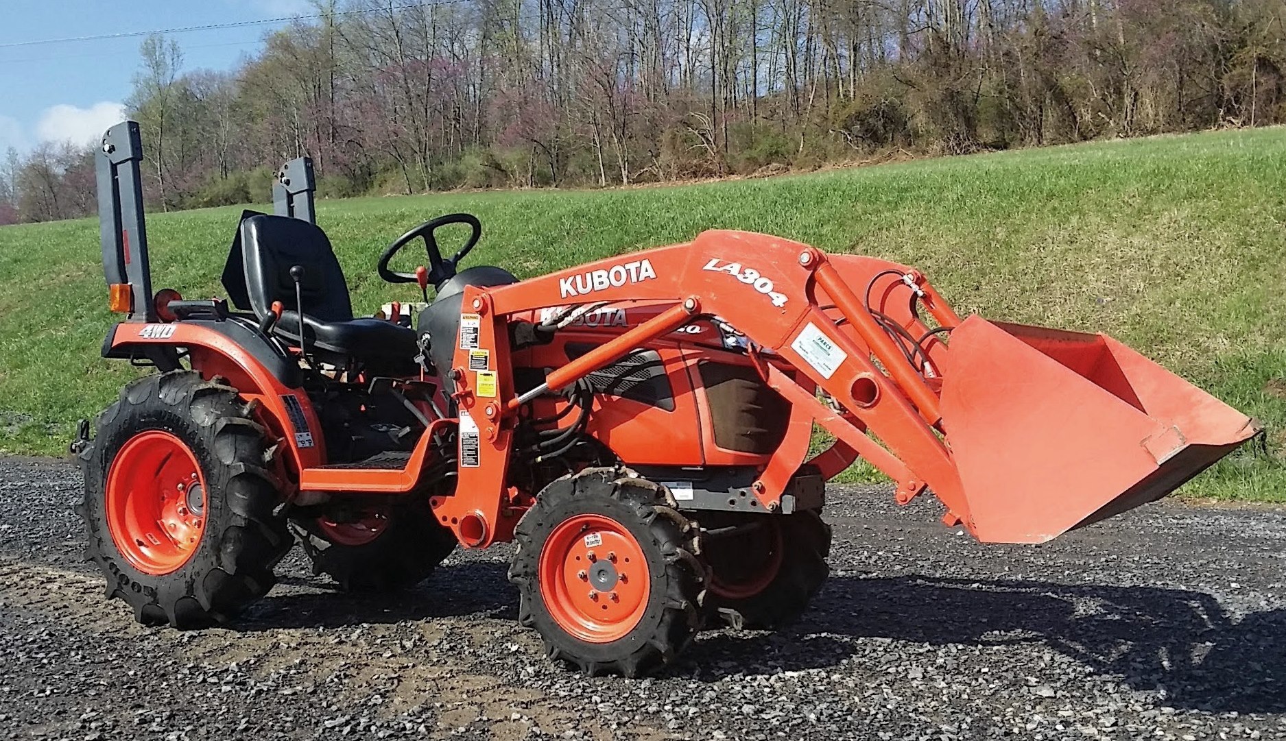 B2320
B2320 B2530
B2530 B26 Backhoe
 B2601
B2601 B2650HSD
 B3030
B3030 B3350
B3350 B6000
B6000 B6100
B6100 B6200
B6200 B7000
B7000 B7001
B7001 B7100HST
 B7200
B7200 B7500
B7500 B7510
B7510 B7800
B7800 B8200HST
 BX1880
 BX2200
 BX2230
 BX2350
 BX2370
 BX23S
BX23S BX25 TLB
 BX2660
 BX2680
 F3680
F3680 L175
L175 L185
L185 L210
L210 L225
L225 L235
L235 L245
L245 L260
L260 L275
L275 L285
L285 L305
L305 GR2120
 L1501
L1501 L2350
L2350 L2550
L2550 L2800
L2800 L3010
L3010 L3200HST
 L3301
L3301 L3560
L3560 L3800
L3800 L4701
L4701 L5740
L5740 M5-091
 M5-111
 M6060
M6060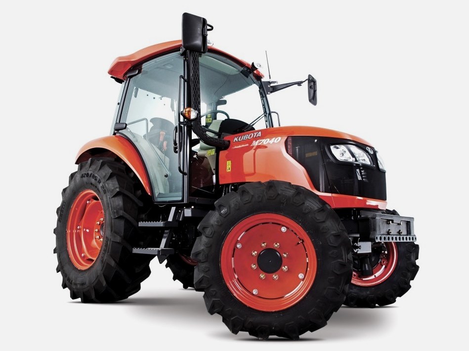 M7040
M7040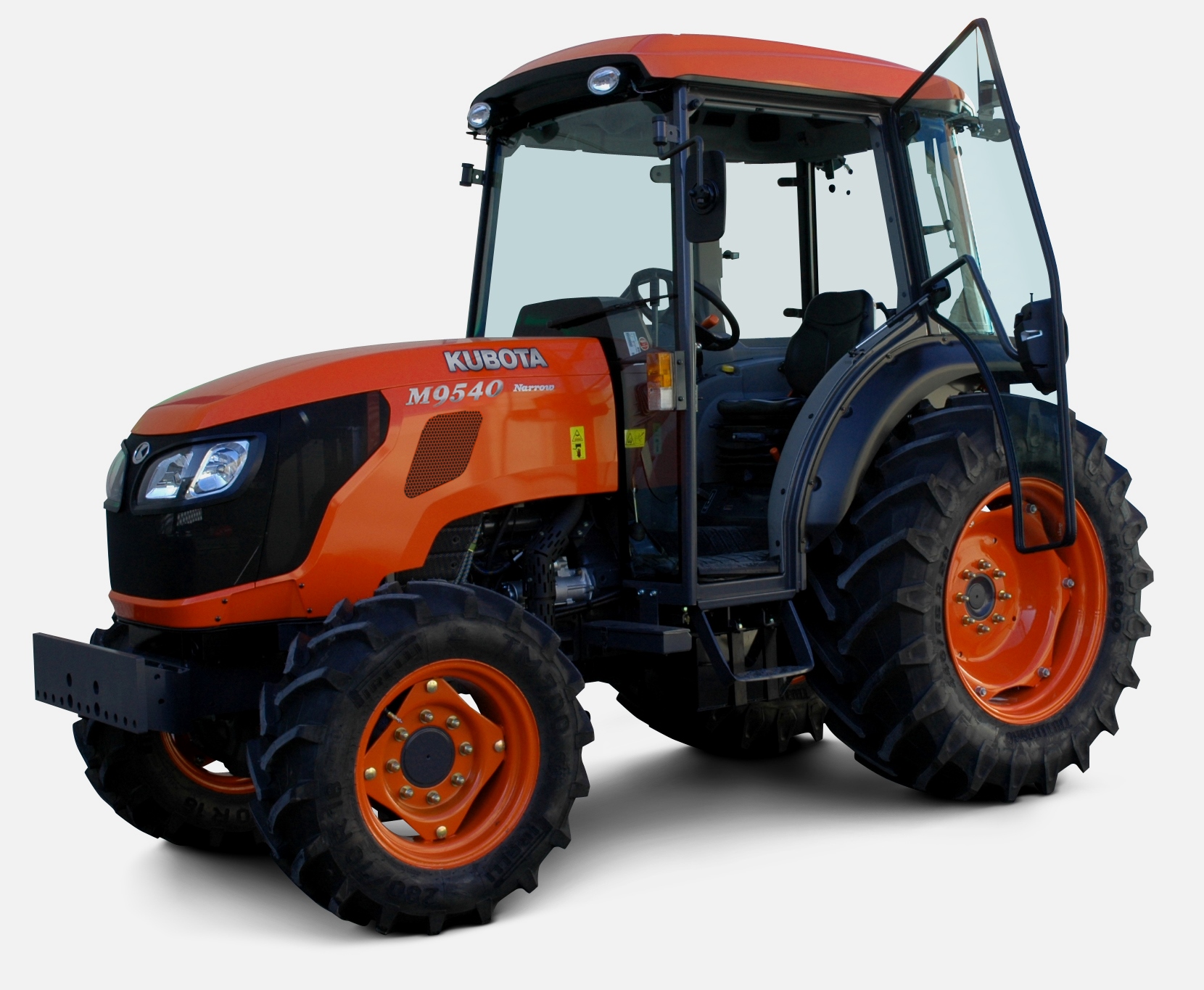 M9540
M9540 M9960
M9960 MX5100
 D662
D662 D722
D722 D750
D750 D782
D782 D850
D850 D902
D902 D905
D905 D950
D950 D1005
D1005 D1100
D1100 D1105
D1105 D1503
D1503 D1703
D1703 D1803
D1803 V1200
V1200 V1205
V1205 V1305
V1305 V1505
V1505 V2203
V2203 V2403
V2403 Z482
Z482 Z602
Z602 Z750
Z750 Z1100
Z1100 Z1300
Z1300 B1630
B1630 BF400
BF400 BF400G
 LA181
LA181 LA203
LA203 LA211
LA211 LA243
LA243 LA271
LA271 LA272
LA272 LA301
LA301 LA302
LA302 LA304
LA304 LA340
LA340 LA344
LA344 LA351
LA351 LA352
LA352 LA364
LA364 LA401
LA401 LA402
LA402 LA434
LA434 LA463
LA463 LA481
LA481 LA482
LA482 LA504
LA504 LA513
LA513 LA514
LA514 LA524
LA524 LA525
LA525 LA534
LA534 LA555
LA555 LA680
LA680 LA681
LA681 LA682
LA682 LA703
LA703 LA714
LA714 LA723
LA723 LA724
LA724 LA764
LA764 LA765
LA765 LA805
LA805 LA844
LA844 LA852
LA852 LA853
LA853 LA854
LA854 LA1002
 LA1055
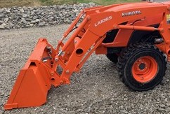 LA1065
 LA1153
 LA1154
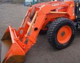 LA1251
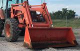 LA1301S
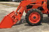 LA1353
 LA1403
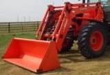 LA1601S
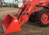 LA1854
 LA1944
 LA1953
 LA2253
 LM2605