
________________________________________________________________________________
Kubota B2150, B9200 - Engine Checking and Service
B2150, B9200 tractors are equipped with a Kubota V1200 4-Cylinder Diesel
Engine.
Kubota B2150, B9200 Engine - Cooling System
Fan Belt Tension
Press the fan belt between fan pulley and pulley with your finger at
force of 10 kgf (98N, 22 lbs). Check if the fan belt deflection is 7 to
9 mm (0.28 to 0.35 in.). If the deflection is not within the factory
specifications, adjust with the tension pulley adjusting nut.
Thermostat's Valve Opening Temperature
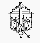
Push down the thermostat valve and insert a string between the valve and
the valve seat. Place the thermostat and a thermometer in a container
with water and gradually heat the water. Hold the string to suspend the
thermostat in the water. When the water temperature rises, the
thermostat valve will open, allowing it to fall down from the string.
Read the temperature at this moment on the thermometer. Continue heating
the water and read the temperature when the valve has risen by about 6
mm (0.236 in.). If the measurement is not acceptable, replace the
thermostat.
Radiator
Radiator Water Leakage - Pour a specified amount of water into the
radiator. Set a radiator tester. Increase water pressure to the
specified pressure of 1.4 kgf/cm2 (137 kPa, 20 psi). Check each section
for water leakage. When water leakage is excessive, replace the
radiator. If water leakage is caused by a small pinhole, correct the
radiator with radiator cement. Radiator Cap Air Leakage - Set a radiator
tester to the radiator cap. Apply the specified pressure of 0.9 kgf/cm2
(98.1 kPa, 12.8 psi). Check if the pressure drop to less than 0.6
kgf/cm2 (59 kPa, 9 psi) in 10 seconds. If the pressure is less than the
factory specification, replace it.
Thermostat and Water Pump
Remove the thermostat cover. Remove the thermostat. Apply a liquid
gasket only at the thermostat cover side of the gasket. Remove the fan
and fan pulley. Remove the water pump from gear case cover. Remove the
water pump flange. Press out the water pump shaft with the impeller on
it. Remove the impeller from the water pump shaft. Remove the mechanical
seal. Replace the mechanical seal with new one.
Checking and Replenish Cooling Water
Remove the radiator cap and check to see that the cooling water level is
just bellow the port. If low, add clean water and antifreeze. Be sure to
close the radiator cap securely. If the cap is loose or improperly
closed, water may leak out and Kubota V1200 engine could overheat. Do
not use an antifreeze and scale inhibitor at the same time.
Checking Fan Belt Tension and Checking Fan
Belt Damage
Check the fan belt for damage. Check if the fan belt is worn and sunk in
the pulley groove. Replace the fan belt if the belt is damaged or nearly
worn out and deeply sunk in the pulley groove. Press the Ian belt
between fan pulley and pulley with your finger at force of 98N (10 kgf,
22 Ibs). Check if the fan belt deflection is 7 to 9 mm (0.28 to 0.35
in.). If the deflection is not within the factory specifications, adjust
with the tension pulley adjusting bolts.
Kubota B2150, B9200 Engine - Fuel System
Injection Timing
Remove the injection pipes. Set the speed control lever for maximum fuel
discharge. Turn the flywheel counterclockwise until fuel flows from the
delivery valve holder. Continue to turn the flywheel slowly, and stop it
as soon as the fuel level at the tip of the delivery valve holder begins
to increase. Check to see if the mark on the flywheel is aligned with
the punch mark. If the timing is out of adjustment, readjust the timing
with shims.
Fuel Tightness of Pump Element
Remove the injection pipe. Install the injection pump pressure tester to
the injection pump. Set the speed control lever to the maximum speed
position. Turn the flywheel ten times or more to increase the pressure.
If the pressure can not reach the allowable limit, replace the pump
element or injection pump assembly.
Fuel Tightness of Delivery Valve
Set a pressure tester to the fuel injection pump. Rotate the flywheel to
increase the pressure to 150 kgf/cm (14.7 MPa, 2133 psi). Align the
plunger with the bottom dead center. Measure the time needed to decrease
the pressure from 150 to 140 kgf/cm2 (14.7 to 13.7 MPa, 2133 to 1990
psi). If the measurement is less than allowable limit, replace the
delivery valve.
Nozzle Injection
Nozzle Injection Pressure - Set the injection nozzle to the nozzle
tester. Slowly move the tester handle to measure the pressure at which
fuel begins jetting out from the nozzle. If the measurement is not
within the factory specifications, disassemble the injection nozzle, and
change adjusting washer until the proper injection pressure is obtained.
Pressure variation with 0.1 mm (0.004 in.) difference of adjusting
washer thickness. Approx. 10kgf/cm2 (981 kPa, 142 psi). Nozzle Spraying
Condition - Set the injection nozzle to a nozzle tester and check the
nozzle spraying condition. If the spraying condition is defective,
replace the nozzle piece. Nozzle Holder - Secure the nozzle retaining
nut with a vise. Remove the nozzle holder, and take out parts inside.
Assemble the nozzle in dean fuel oil. Install the push rod, noting its
direction. After assembling the nozzle, be sure to adjust the fuel
injection pressure.
Fuel Tightness of Needle Valve Seat
Set the injection nozzle to a nozzle tester. Apply a pressure 130kgf/cm
(12.75 MPa, 1849 psi). After keeping the nozzle under this pressure for
10 seconds, check to see if fuel leaks from the nozzle. If fuel should
leak, replace the nozzle piece.
Cleaning Air Filter Element and Fuel Filter
Cleaning Air Filter Element - When dry dust adheres. Use dean dry
compressed air on the inside of the element. Air pressure at the nozzle
must not exceed 690 kPa (7kgf/cm2, 100psi). Maintain reasonable distance
between the nozzle and the filter. Cleaning Fuel Filter - Close the fuel
filter cock. Unscrew the screw ring and remove the cup, and rinse the
inside with kerosene.
Kubota B2150, B9200 Engine - Lubricating
System
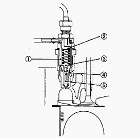
Engine Oil Pressure and Oil Strainer
Engine Oil Pressure - Remove the oil switch and set a pressure tester.
Start the engine. After warming up, measure the oil pressure of both
idling and rated speeds. Oil Strainer - Detach the oil pan by lightly
tapping the groove of the pan with a wooden hammer. Remove the mounting
bolt of oil filter. Detach oil filter, being careful of the O-ring.
Oil Pump
Straighten the claw of the claw washer of the oil pump, and remove the
nut. Draw out the oil pump drive gear with gear puller. Remove the four
oil pump mounting bolts. Detach the oil pump. Rotor Lobe Clearance -
Measure the clearance between lobes of the inner rotor and the outer
rotor with a feeler gauge. If the clearance exceeds the allowable limit,
replace the oil pump rotor assembly. Clearance between Outer Rotor and
Pump Body - Measure the clearance between the outer rotor and the pump
body with a feeler gauge. If the clearance exceeds the allowable limit,
replace the oil pump rotor assembly. Clearance between Rotor and Cover -
Put a strip of press gauge onto the rotor face with grease. Install the
cover and tighten the screws. Remove the cover carefully, and measure
the width of the press gauge with a sheet of gauge. If the clearance
exceeds the allowable limit, replace oil pump rotor assembly.
Checking Engine Oil Level
Level the engine. To check the oil level, draw out the dipstick, wipe it
clean, reinsert it, and draw it out again. Check to see that the oil
level lies between the two notches. If the level is too low, add new oil
to the specified level. When checking the oil level, make sure the
tractor is on a flat surface. It is impossible to check accurately if
the tractor is not level. Check the oil level before starting or more
than 3 minutes after the engine has stopped. At other times, the check
will not be accurate as oil stagnates in certain engine parts. When
using an oil of different maker or viscosity from the previous one,
drain old oil. Never mix two different types of oil.
Changing Engine Oil
After warming up, stop the engine. To change the used oil, remove the
drain plug at the bottom of the engine and drain off the oil completely.
Reinstall the drain plug. Fill the new oil up to the upper notch on the
dipstick. Change the type of engine oil according to the ambient
temperature. Above 25C - SAE 30 or 10W-30, 0°C to 25C - SAE 20 or
10W-30, Below 0C - SAE 10 W or 10W-30.
Changing Engine Oil Filter Cartridge
Remove the oil filter cartridge with a filter wrench. Apply engine oil
to the rubber gasket on the new cartridge. Screw the new cartridge in by
hand. Over-tightening may cause deformation of rubber gasket. After
cartridge has been replaced, engine oil normally decreases a little.
Check the oil level and add new oil to the specified level.
Kubota B2150, B9200 Engine - Cylinder and
Cylinder Head
Cylinder
Cylinder Wear - Measure the I.D. of the cylinder at the six positions
with a cylinder gauge to find the maximum and minimum I.D.'s. Get the
difference (Maximum wear) between the maximum and the minimum I.D.'s. If
the wear exceeds the allowable limit, bore and hone to the oversize
dimension. Visually check the cylinder wall for scratches. If deep
scratches are found, the cylinder should be bored. Cylinder I.D
(V1200-B) - 75.000 to 75.019 mm (2.9528 to 2.9535 in).
Cylinder Head
Cylinder Head Surface Flatness - Thoroughly clean the cylinder head
surface. Place a straightedge on the cylinder head's four sides and two
diagonal. Measure the clearance with a feeler gauge. If the measurement
exceeds the allowable limit, correct it with a surface grinder. Do not
place the straight edge on the combustion chamber. Be sure to check the
valve recessing after correcting. Cylinder Head Flaw - Prepare an air
spray red check. Clean the surface of the cylinder head with detergent.
Spray the cylinder head surface with the red permeated liquid. Leave it
five to ten minutes after spraying. Wash away the red permeated liquid
on the cylinder head surface with the detergent. Spray the cylinder head
surface with white developer. If flawed, it can be identified as red
marks.
Valve Recessing
Clean the cylinder head surface, valve face and valve seat. Insert the
valve into the valve guide. Measure the valve recessing with a depth
gauge. If the measurement exceeds the allowable limit, replace the
valve. If it still exceeds the allowable limit after replacing the
valve, replace the cylinder head. Clearance between Valve Stem and guide
- Remove carbon from the valve guide section. Measure the valve stem
O.D. with an outside micrometer. Measure the valve guide I.D. of the
cylinder head at the most wear part as shown in the figure below with a
small hole gauge. And calculate the clearance. If the clearance exceeds
the allowable limit, replace the valves. If it still exceeds the
allowable limit, replace the valve guide. Push Rod Alignment - Check the
both end of the push rod for cracks, damage and unusual wear. Measure
the bending of the push rod with a dial indicator. If the measurement
exceeds the allowable limit, replace the push rod.
Correcting Valve
Correcting Valve Seat - Slightly correct the seat surface with a 45 or
30 degrees valve seat cutter. Fitting the valve, check the contact
position of the valve face and seat surface with prussian blue. Visual
check - If the valve has been used for a long period, the seat tends to
come in contact with the upper side of the valve face. Grind the upper
surface of the seat with a 0.262 rad (15 degrees) valve seat cutter
until the valve seat touches to the center of the valve face. Grind the
seat with 45/30 degrees valve seat cutter again, and visually recheck
the contact between the valve and seat. Valve Spring Setting Load -
Place the valve spring on a tester and compress it to the same length it
is actually compressed the engine. Read the compression load on the
gauge. If the measurement is less than the allowable limit, replace it.
Replacing Valve
Replacing Valve Guide - Press the used value guide out from the cylinder
head's lower side using a valve guide replacing tool. Apply engine oil
to the outer surface of the new valve guide, and press fit the valve
guide from the cylinder head's upper side until the flange part of the
valve guide contacts the cylinder head. Be careful not to strike valve
guide with a hammer, etc. during replacement. Free Length and Tilt of
Valve Spring - Measure the length A with vernier calipers. If the
measurement is less than the allowable limit, replace. Put the spring on
a surface plate, place a square on the side of the spring, and check to
see if the entire side is in contact with the square. Rotate the spring
and measure the maximum. If the measurement exceeds the allowable limit,
replace. Check the entire surface of the spring for scratches. Replace
it, if any.
Kubota B2150, B9200 - Timing Gear and Camshaft
Timing Gear
Timing Gear Backlash - Set a dial indicator (lever type) with its tip on
the gear tooth. Move the gear to measure the backlash, holding its
mating gear. If the backlash exceeds the allowable limit, check the oil
clearance of the shafts and gear. If the oil clearance is proper,
replace the gear. Clearance between Idle Gear Shaft and Idle Gear
Bushings - Measure the idle gear shaft O.D. with an outside micrometer.
Measure the idle gear bushings I.D. with an inside micrometer, and
calculate the clearance. If the clearance exceeds the allowable limit,
replace the bushing. Replacing Idle Gear Bushings - Press the used
bushings out using a idle gear bushing replacing tool. Press fit new
bushings.
Camshaft
End Play of Camshaft - Pull the cam gear with the camshaft to its end.
Measure the clearance between the cam gear and camshaft stopper. If the
clearance exceeds the allowable limit, replace the camshaft stopper.
Camshaft Alignment - Support the camshaft with V blocks on the surface
plate at both end journals. Set a dial indicator with its tip on the
intermediate journal. Measure the camshaft alignment. If the measurement
exceeds the allowable limit, replace the camshaft. Intake and Exhaust
Cam Height - Measure the height of the cam at its highest point with an
outside micrometer. If the measurement is less than the allowable limit,
replace it. Oil Clearance of Camshaft Journal - Measure the camshaft
journal O.D. with an outside micrometer. Measure the cylinder block bore
I.D. for camshaft with an inside micrometer. Calculate the oil
clearance. If the clearance exceeds the allowable limit, replace the
camshaft.
Kubota B2150, B9200 - Piston and Connecting
Rod
Piston
Piston Pin-Bore I.D. - Measure the LD. of the piston pin-bore in both
the horizontal and vertical directions with a cylinder gauge. If the
measurement exceeds the allowable limit, replace the piston. Oil
Clearance between Piston Pin and Small End Bushing - Measure the O.D. of
the piston pin where it contacts the bushing with an outside micrometer.
Measure the I.D. of the piston pin bushing at the connecting rod small
end with a cylinder gauge. Calculate the oil clearance. If the clearance
exceeds the allowable limit, replace the bushing. If it still exceeds
the allowable limit, replace the piston pin.
Piston Ring
Clearance between Piston Ring and Groove - Remove carbon from the ring
grooves. Measure the clearance between the ring and the groove with a
Feeler gauge or depth gauge. If the clearance exceeds allowable limit,
replace the ring since compression leak and oil shortage result. If the
clearance still exceeds the allowable limit after replacing the ring,
replace the piston. Piston Ring Gap - Insert the piston ring into the
lower part of the liner (the least worn out part) with the piston.
Measure the ring gap with a feeler gauge. If the gap exceeds the
allowable limit, replace the ring.
Connecting Rod
Replacing Connecting Rod Small End Bushing - Press out the small end
bushing with a connecting rod small end bushing replacing tool. Clean a
new small end bushing and bore, and apply engine oil to them. Insert a
new bushing onto the tool and press-fit it. with a press so that the
seam of bushing positions as shown in the figure, until it is flash with
the connecting rod. Drill a hole to the bushing with aligning the oil
hole of connecting rod using 4.0 mm dia. (0.157 in. dia.) drill. Oil
clearance between piston pin and small end bushing - 0.015 to 0.075 mm.
Connecting Rod Alignment - Since the I.D. of the connecting rod small
end bushing is the basis of this check, check the bushing for wear
beforehand. Install the piston pin into the connecting rod. Install the
connecting rod on the connecting rod alignment tool. Put a gauge over
the piston pin and move it against the face plate. If the gauge does not
fit squarely against the face plate, measure the space between the pin
of the gauge and the face plate. If the measurement exceeds the
allowable limit, replace the connecting rod.
Kubota B2150, B9200 - Crankshaft
End Play of Crankshaft
Move the crankshaft to the flywheel side. Set a dial indicator to the
crankshaft. Measure the end play by pulling the crankshaft toward the
crank gear. If the measurement exceeds the allowable limit, replace the
thrust bearings. Crankshaft Alignment - Support the crankshaft with
V-blocks on the surface plate and seta dial indicator with ttstip on the
intermediate journal at right angle. Rotate the crankshaft on the
V-blocks and get the misalignment (half of the measurement). If the
misalignment exceeds the allowable limit, replace the crankshaft.
Oil Clearance between Crank Pin and Crank Pin
Bearing
Clean the crank pin and crank pin bearing. Put a strip of press gauge on
the center of the crank pin in each direction as shown in the figure.
Never insert the press gauge into the crank pin oil hole. Install the
connecting rod cap and tighten the screws to the specified torque, and
remove the cap again. Fasten the crankshaft so that it does not turn.
Measure the amount of the flattening with the scale and get the oil
clearance. If the clearance exceeds the allowable limit, replace the
bearing. When the oil clearance is to be measured by removing the
crankshaft, tighten the connecting rod cap with the specified torque,
then measure the crank pin bearing I.D. with a cylinder gauge or an
inside micrometer. And measure the crank pin O.D. with an outside
micrometer. Calculate the oil clearance.
Crankshaft Sleeve Wear and Replacing
Crankshaft Sleeve
Measure the wear of the crankshaft sleeve using a . surface roughness
tester. If the measurement exceeds the allowable limit, replace the
crankshaft sleeve. Remove the used crankshaft sleeve using a special-use
puller set. Set the sleeve guide C to the crankshaft. Set the stopper C
to the crankshaft. Heat a new sleeve to a temperature between 150 and
200C, and fix the sleeve to the crankshaft. Press fit the sleeve using
the auxiliary socket for pushing.
Crankshaft Bearing
Oil Clearance between Crankshaft Journal and Crankshaft Bearing 1 -
Measure the O.D. of the crankshaft journal with an outside micrometer,
Measure the I.D. of the crankshaft bearing 1 with an inside micrometer.
Calculate the oil clearance. If the clearance exceeds the allowable
limit, replace the crankshaft bearing 1. Replacing Crankshaft Bearing 1
- Press out the bearing 1 with crankshaft bearing 1 replacing tool.
Clean a new bearing 1 and bore, and apply engine oil to them. Press fit
a new bearing 1 using a inserting tool, taking due care to see that the
seam of bearing 1 faces the exhaust manifold side. Oil Clearance between
Crankshaft Journal and Crankshaft Bearing 2 - Clean the crankshaft
journal and crankshaft bearing. Put a strip of press gauge on the center
of the journal. Never insert the press gauge into the oil hole of the
journal. Install the main bearing case and tighten the screws to the
specified torque, and remove the cases again. Measure the amount of the
flattening with the scale and get the oil clearance. If the clearance
exceeds the allowable limit, replace the crankshaft bearing.
________________________________________________________________________________
________________________________________________________________________________________
 SPECIFICATIONS
 LOADERS
 ENGINES
 INSTRUCTIONS
 PROBLEMS
________________________________________________________________________________________
 B2320
B2320 B2630
B2630 B2920
B2920 B3300SU
 BX2360
________________________________________________________________________________________
 L245
L245 L260
L260 L275
L275 L285
L285 L305
L305________________________________________________________________________________________
________________________________________________________________________________________
 D662
D662 D722
D722 D750
D750 D782
D782 D850
D850________________________________________________________________________________________
 LA302
LA302 LA304
LA304 LA340
LA340 LA344
LA344 LA351
LA351________________________________________________________________________________________
 BX2660
 L2501
L2501 L3240
L3240 L3540
L3540 L3940
L3940________________________________________________________________________________________
 D902
D902 D905
D905 D950
D950 D1005
D1005 D1100
D1100________________________________________________________________________________________
________________________________________________________________________________________
 B1630
B1630 BF400
BF400 BF400G
 LA181
LA181 LA203
LA203________________________________________________________________________________________
 LA211
LA211 LA243
LA243 LA271
LA271 LA272
LA272 LA301
LA301________________________________________________________________________________________
 L175
L175 L185
L185 L210
L210 L225
L225 L235
L235________________________________________________________________________________________
 D1105
D1105 D1503
D1503 D1703
D1703 D1803
D1803 V1200
V1200________________________________________________________________________________________
 L4400
L4400 L4600
L4600 L5040
L5040 L5740
L5740 MX4700
________________________________________________________________________________________
 LA352
LA352 LA364
LA364 LA401
LA401 LA402
LA402 LA403
LA403________________________________________________________________________________________
 LA434
LA434 LA463
LA463 LA481
LA481 LA482
LA482 LA504
LA504________________________________________________________________________________________
 V1205
V1205 V1305
V1305 V1505
V1505 V2203
V2203 V2403
V2403________________________________________________________________________________________
 B2710
B2710 BX23S
BX23S B3350
B3350 BX1880
 L4701
L4701________________________________________________________________________________________
 LA513
LA513 LA514
LA514 LA524
LA524 LA525
LA525 LA534
LA534________________________________________________________________________________________
 LA555
LA555 LA680
LA680 LA681
LA681 LA682
LA682 LA703
LA703________________________________________________________________________________________
 Z482
Z482 Z602
Z602 Z750
Z750 Z1100
Z1100 Z1300
Z1300________________________________________________________________________________________
 M100GX
 M135GX
 M6040
M6040 M8540
M8540 M95X
M95X________________________________________________________________________________________
 LA714
LA714 LA723
LA723 LA724
LA724 LA764
LA764 LA765
LA765________________________________________________________________________________________
 LA805
LA805 LA844
LA844 LA852
LA852 LA853
LA853 LA854
LA854________________________________________________________________________________________
 M5-091
 BX2680
 MX5200
 BX2380
 L3901
L3901________________________________________________________________________________________
 LA1002
 LA1055
 LA1065
 LA1153
 LA1154
________________________________________________________________________________________
 LA1251
 LA1301S
 LA1353
 LA1403
 LA1601S
________________________________________________________________________________________
 LA1854
 LA1944
 LA1953
 LA2253
 LM2605