________________________________________________________________________________
Kubota B2301, B2311, B2231 - Transmission
Kubota B2301, B2311, B2231 - Transmission
Assembly Parts
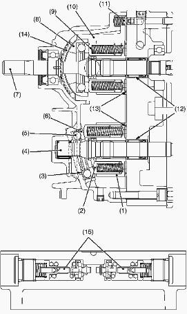
1-Cylinder Block (Motor), 2-Piston, 3-Thrust Collar, 4-Motor Shaft,
5-Thrust Ball Bearing, 6-Thrust Collar, 7-Pump Shaft, 8-Swashplate,
9-Piston, 10-Cylinder Block (Pump), 11-Charge Relief Valve, 12-Needle
Bearing, 13-Valve Plate, 14-Cradle Bearing, 15-Check and High Pressure
Relief Valve,
Range Gear Shift
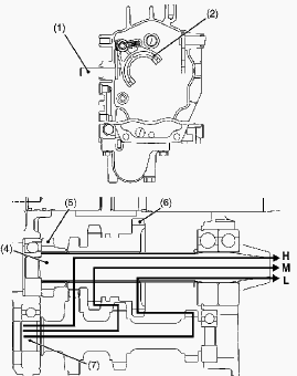
1. Range Gear Shift Lever, 2. Range Shift Fork, 3. Range Shift Arm, 4.
6T Bevel Pinion Shaft, 5. 13T Gear (for Front Wheel Drive), 6.
14T-21T-29T Gear, 7. 23T-16T-14T Sub Shaft, L - LOW Range, M - MID
Range, H - HIGH Range
Range gear shift lever (1) is located at left side fender. Range gear
shift lever (1) can select three speed range, low speed, mid speed and
high speed. Range gear shift lever (1) and 14T-21T-29T gear (6) are
linked with range shift arm (3) and range shift fork (2) etc. Three
range gear shifts are selected by shifting the 14T-21T-29T gear (6) on
6T bevel pinion shaft to 23T-16T-14T sub shaft (7).
Low Speed Position: 14T of 23T-16T-14T Sub Shaft (7) - 29T of
14T-21T-29T Gear (6) - 6T Bevel Pinion Shaft (4).
Middle Speed Position: 16T of 23T-16T-14T Sub Shaft (7) - 21T of
14T-21T-29T Gear (6) - 6T Bevel Pinion Shaft (4).
High Speed Position: 23T of 23T-16T-14T Sub Shaft (7) - 14T of
14T-21T-29T Gear (6) - 6T Bevel Pinion Shaft (4).
Front Wheel Drive Section
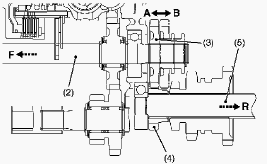
1 - Front Wheel Drive Lever, 2 - Front Wheel Drive Shaft, 3 - 20T
Shifter Gear, 4 - 13T Gear, 5 - 6T Bevel Pinion Shaft, A - 4WD Position,
B - 2WD Position, F - Power to Front Wheels, R - Power to Rear Wheels
Front wheel drive lever (1) is located at the right side fender. Front
wheel drive lever (1) and shifter are linked. 20T shifter gear (3) is
located on the front wheel drive shifter (2). 2-wheel drive or 4-wheel
drive is selected by changing the position of 20T shifter gear (3)
reverse or forward. When the font wheel drive lever (1) is set to "4
Wheel Drive" position, 20T shifter gear (3) slides forward, meshes the
13T gear (4) on the 6T bevel pinion shaft (5). In this state, power from
the 6T bevel pinion shaft (5) is transmitted through 20T shifter gear
(3) to the front wheel drive shaft (2) and the front wheels.
Kubota B2301, B2311, B2231 Tractor - Independent PTO
Independent PTO Clutch
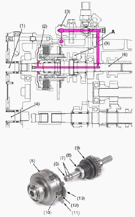
1 - HST Pump Shaft, 2 - Independent PTO Clutch, 3 - Independent PTO
Control Valve, 4 - HST Motor Shaft, 5 - Case, 6 - PTO Clutch Shaft, 7 -
Seal, 8 - Bearing, 9 - Shifter, 10 - Clutch Discs and Plates, 11 - Brake
Plate 4, 12 - Brake Disc, 13 - Brake Plate 2
Independent PTO clutch (2) is located behind the HST pump shaft (1) in
the transmission case. Independent PTO clutch (2) is operated with
pressured hydraulic oil forced from the independent PTO control valve
(3). When independent PTO lever is shifted to "ENGAGED" position,
hydraulic oil is forced through the transmission case inner passage (A)
and PTO clutch shaft (6) to PTO clutch. In this state, power from HST
pump shaft is transmitted through independent PTO clutch (2) to
independent PTO clutch shaft (6). When independent PTO lever is shifted
to "DISENGAGED" position, hydraulic oil is not forced to the PTO clutch.
In this state, power from HST pump shaft (1) is not transmitted to
independent PTO clutch shaft (6).
Independent PTO Control Valve Checking
Disconnect the OPC switch connector and remove the seat. Remove the
plate. Remove the 3-point hitch lowering speed knob. Remove the plug
with a hexagon wrench. Install the adapter to the independent PTO
control valve. Connect the cable and the pressure gauge to the adapter.
Reassemble the plate. Start the engine and set at the maximum speed.
(Pressure at "ENGAGED" position) Move the independent PTO lever to
"ENGAGED" position A. Measure the pressure. (Pressure at "DISENGAGED"
position). Move the independent PTO lever to position B. Measure the
pressure. If the pressure is not the factory specifications, adjust
setting pressure with (the adjusting) shims. Independent PTO valve
setting pressure (ENGAGED position) - 1.1 to 1.5 MPa (160 to 218 psi).
Independent PTO valve setting pressure (DISENGAGED position) - 0 MPa (0
psi).
Kubota B2301, B2311, B2231 Independent PTO Troubleshooting
PTO Clutch Slip
Operating pressure is low - Check PTO control valve setting pressure.
Inspect clutch disc or plate. Replace PTO clutch or other parts.
Independent PTO control valve malfunctioning - Check PTO control valve
setting pressure. Inspect or replace poppet or PTO control valve.
Clutch disc or drive plate excessively worn - Check PTO control valve
setting pressure. Inspect or replace clutch disc or plate.
Deformation of piston or return plate - Inspect return plate or piston.
Replace return plate or piston.
PTO Shaft Does Not Rotate
PTO clutch malfunctioning Solution order - Check PTO control valve
setting pressure. Replace PTO clutch or other parts.
PTO Clutch Operating Pressure is Low
Transmission oil improper or insufficient - Check transmission oil.
Relief valve malfunctioning - Replace poppet.
PTO Clutch Drags
Brake plate excessively worn - Replace brake plate. Return spring weaken
or broken - Inspect or replace return spring.
Kubota B2301, B2311, B2231 Hydrostatic Transmission - Checking And
Adjusting
Charge Relief Pressure

Remove the cover. Remove the plug from P1 port (reverse) or P2 port
(forward). Install the adaptor to P1 port or P2 port. Install the cable
and low pressure gauge to the adaptor. Start the engine and warm the oil
before testing. Change the range gear shift lever to "NEUTRAL" position.
Operate engine at the rated speed. Release the foot from the HST pedal.
Read the low pressure gauge to measure the charge relief pressure. If
the measurement is not same as factory specification, check the charge
relief valve and the related hydraulic components. Low pressure gauge is
2.9 MPa (30 kgf/cm2, 427 psi) full scale. Charge pressure - 0.4 to 0.6
MPa / 60 to 80 psi. Checking port plug - 29 to 44 Nm / 21.7 to 32.5
lbf-ft.
High Pressure Relief Valve (Reverse)
Remove the cover. Remove the plug from P1 port (reverse). Install the
adaptor to P1 port. Install the cable and high pressure gauge. Start the
engine and warm the oil before testing. Check to see that parking brake
is applied. Place the range gear shift lever to "HIGH" position. Operate
the engine at the rated speed. Depress the rear side pedal of the HST
pedal. Read the high pressure gauge to measure the high pressure relief
valve pressure. If the measurement is not the same as factory
specification, check the check and high pressure relief valve assembly.
High pressure gauge is 40 MPa (400 kgf/cm2, 5800 psi) full scale. Oil
temperature: 50 C (122 F). Check and high relief pressure - 23 to 25 MPa
/ 3400 to 3600 psi. Checking port plug - 29 to 44 Nm / 21.7 to 32.5
lbf-ft.
High Pressure Relief Valve (Forward)
Remove the cover. Remove the plug from P2 port (forward). Install the
adaptor to P2 port. Install the cable and high pressure gauge. Start the
engine and warm the oil before testing. Check to see that parking brake
is applied. Place the range gear shift lever to "HIGH" position. Operate
the engine at the rated speed. Depress the front side pedal of the HST
pedal. Read the high pressure gauge to measure the high pressure relief
valve pressure. If the measurement is not same as factory specification,
check the check and high pressure relief valve assembly.
Kubota B2301, B2311, B2231 - PTO Clutch Case and Front Wheel Drive Shaft
Separating Transmission Case and PTO Clutch Case
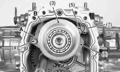
1 - Transmission Case, 2 - Differential Case, 3 - PTO Clutch Case, 4 -
PTO Brake Plate 4 Mounting Bolt, 5 - PTO Brake Plate 4, 6 - PTO Brake
Plate 2, 7 - Transmission Case Groove, A - Position, B - Position
Remove the transmission case mounting bolts. Separate the transmission
case from the differential case. Remove the PTO brake plate 4 mounting
bolt. Install the PTO brake plate 4 to the transmission case groove
securely.
Bevel Pinion Shaft
Remove the bevel pinion shaft assembly and range gear shaft assembly
from the transmission case. Remove the spacer. Install the spacer to the
transmission case. Install the bevel pinion shaft assembly and range
gear shaft assembly. Transmission case mounting bolt (M10) and nut -
39.3 to 44.1 Nm / 29.0 to 32.5 lbf-ft. Hydraulic cylinder mounting bolt
(M10) and nut - 39.3 to 44.1 Nm / 29.0 to 32.5 lbf-ft.
Sub Gear Shaft Assembly
Remove the circlip from the sub gear shaft. Remove the sub gear shaft
assembly from the transmission case.
4WD Shaft
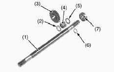
1.4WD Shaft, 2.Collar, 3.26T Gear, 4.Needle Bearing, 5.Collar,
6.Circlip, 7.Ball Bearing
Remove the circlip from the 4WD shaft. Remove the 4WD gear from the 4WD
shaft. Remove the 4WD shaft with the 26T gear. Remove the 26T gear and
the ball bearing.
4WD Shift Lever
Remove the bolt and the washer with rubber. Install the 4WD gear to the
4WD shaft. Install the 4WD shaft arm to the 4WD gear. Install the
O-rings to the 4WD shift arm.
Kubota B2301, B2311, B2231 Tractor - Differential Gear Section
Rear Axle Case and Rear PTO Cover
Remove the rear axle mounting bolts. Remove the left rear axle case and
the right rear axle case from the differential case. Remove the rear PTO
cover mounting bolts and the rear PTO cover. Apply liquid gasket to the
joint surface of the rear axles cases and the rear PTO cover.
Differential Bearing Holder (RH)
Remove the differential holder mounting bolts. Remove the differential
holder and shims. 0.2 mm (0.008 in.) shim / 0.5 mm (0.020 in.) shim.
Rear axle case (LH and RH) mounting bolt for aluminum material (M10) -
39.3 to 44.1 Nm / 29.0 to 32.5 lbf-ft. Rear PTO cover mounting bolt for
aluminum material (M10) - 39.3 to 44.1 Nm / 29.0 to 32.5 lbf-ft.
Differential bearing holder mounting bolt for aluminum material (M8) -
17.7 to 20.5 Nm / 13.1 to 15.1 lbf-ft.
Differential Gear Assembly
Remove the internal circlip from the differential case. Remove the
shims. Remove the differential gear assembly from the differential case.
When reassembling: 0.5 mm (0.020 in.), shim 0.6 mm (0.024 in.), shim 0.7
mm (0.028 in.), shim 0.8 mm (0.031 in.).
Differential Side Gear and Differential Pinion
Put parting marks on the differential pinion and the differential side
gear. Tap out the dowel pin. Remove the differential pinion shaft.
Remove the differential pinion, differential side gear and shim. Install
the differential pinion and differential side gear, aligning the parting
marks.
Kubota B2301, B2311, B2231 Tractor - Hydrostatic Transmission Service
Pump Shaft
Pull out the pump shaft from the HST housing case. Check the oil seal
surface, the bearing surface and the bearing. If the shaft is rough or
grooved, replace it. If the bearing is worn, replace it.
Cylinder Block Face
Check the polished face of cylinder block for scoring. If scored,
replace cylinder block assembly.
Valve Swash Plate Bearing Face
Check the swash plate bearing for scratches and excessive wear. If worn
or scored, replace it. Apply liquid lock to the screw.
Thrust Collars, Thrust Ball Bearing and Swash Plate Surface
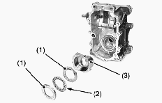
1-Thrust Collar, 2-Thrust Ball Bearing, 3-Swash Plate
Check the thrust collar for scratches and excessive wear. If worn or
scored, replace it. Check the thrust ball bearing surface for scratches
and excessive wear. If worn or scored, replace it. Check the swash plate
for scratches and excessive wear. If worn or scored, replace it.
Thrust collars and Thrust Ball Bearing (Motor Side)
Check the thrust collars for scratches and excessive wear. If worn or
scored, replace it. Check the thrust ball bearing for scratches and
excessive wear. If worn or scored, replace it.
Center Section Oil Seals and Bearings
Check the oil seals for damage. Check the needle bearings for wear. If
the needle bearings and oil seals are worn, replace all seals and needle
bearings. After checking, coat the bearing with hydrostatic transmission
oil and the oil seal lip with grease. Tightening torque: Screw (M3) -
1.5 Nm / 1.1 lbf-ft.
Check and High Pressure Relief Valve
Check the valve plug and valve for scratches and damage. Check the valve
seat in the port block for damage. Check the spring for breakage and
wear. If anything unusual, replace the check and high pressure relief
valve assembly.
Charge Relief Valve
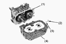
1-HST Housing, 2-Spring, 3-Poppet, 4-Center Section
Check the spring for breakage and wear. If it is unusual, replace it.
Cylinder Block Bore and Pistons
Check the pistons for their free movement in the cylinder block bores.
If the piston or the cylinder block bore is scored, replace cylinder
block assembly. Do not interchange pistons between pump and motor
cylinder block. Pistons and cylinder blocks are matched.
Kubota B2301, B2311, B2231 - Independent PTO Clutch Service
Checking Bearing
Hold the inner race, and push and pull the outer race in all directions
to check for wear and roughness. Apply transmission fluid to the
bearing, and hold the inner race. Then, turn the outer race to check
rotation. If there is any problem, replace it. Valve plug - 59 to 78 Nm
/ 44 to 57 lbf-ft. Clearance between piston and bore - 0.02 to 0.03 mm /
0.0008 to 0.001 in.
Clutch Disc Wear
Measure the clutch disc thickness with vernier calipers. If the
thickness is less than the allowable limit, replace it.
Steel Plate and Pressure Plate Wear
Measure the steel plate thickness with vernier calipers. Measure the
pressure plate thickness with vernier calipers. If the thickness is less
than the allowable limit, replace.
Piston Return Spring Free Length and Tension
Measure the free length of the piston return spring with vernier
calipers. Place the piston return spring on a spring compression tester
and compress to the specified length, and read the gauge. If the
measurement is less than the allowable limit, replace.
________________________________________________________________________________
________________________________________________________________________________________
________________________________________________________________________________________
| KUBOTA TRACTORS SPECIFICATIONS |
________________________________________________________________________________________
________________________________________________________________________________________
________________________________________________________________________________________
________________________________________________________________________________________
________________________________________________________________________________________
________________________________________________________________________________________
________________________________________________________________________________________
________________________________________________________________________________________
________________________________________________________________________________________
________________________________________________________________________________________
________________________________________________________________________________________
________________________________________________________________________________________
________________________________________________________________________________________
________________________________________________________________________________________
________________________________________________________________________________________
| KUBOTA ENGINES DATA AND SERVICE SPECS |
________________________________________________________________________________________
________________________________________________________________________________________
________________________________________________________________________________________
________________________________________________________________________________________
________________________________________________________________________________________
| KUBOTA FRONT END LOADERS |
________________________________________________________________________________________
________________________________________________________________________________________
________________________________________________________________________________________
________________________________________________________________________________________
________________________________________________________________________________________
________________________________________________________________________________________
________________________________________________________________________________________
________________________________________________________________________________________
________________________________________________________________________________________
________________________________________________________________________________________
________________________________________________________________________________________
________________________________________________________________________________________
| KUBOTA TRACTORS TROUBLESHOOTING | ||||
| L235 | L2501 | L2550 | L275 | L3110 |
| L3301 | L35 | L3710 | L3901 | L4310 |
| L5030 | M4700 | M5700 | M6040 | M6800 |
| M8200 | M8540 | M9000 | MX5100 | MX5200 |

 SPECIFICATIONS
 LOADERS
 ENGINES
 MAINTENANCE
 PROBLEMS
 B1241
B1241 B1600
B1600 B1700
B1700 B1750
B1750 B21 Backhoe
 B2150
B2150 B2301
B2301 B2320
B2320 B2530
B2530 B26 Backhoe
 B2601
B2601 B2650HSD
 B3030
B3030 B3350
B3350 B6000
B6000 B6100
B6100 B6200
B6200 B7000
B7000 B7001
B7001 B7100HST
 B7200
B7200 B7500
B7500 B7510
B7510 B7800
B7800 B8200HST
 BX1880
 BX2200
 BX2230
 BX2350
 BX2370
 BX23S
BX23S BX25 TLB
 BX2660
 BX2680
 F3680
F3680 L175
L175 L185
L185 L210
L210 L225
L225 L235
L235 L245
L245 L260
L260 L275
L275 L285
L285 L305
L305 GR2120
 L1501
L1501 L2350
L2350 L2550
L2550 L2800
L2800 L3010
L3010 L3200HST
 L3301
L3301 L3560
L3560 L3800
L3800 L4701
L4701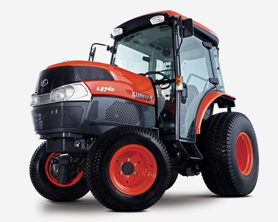 L5740
L5740 M5-091
 M5-111
 M6060
M6060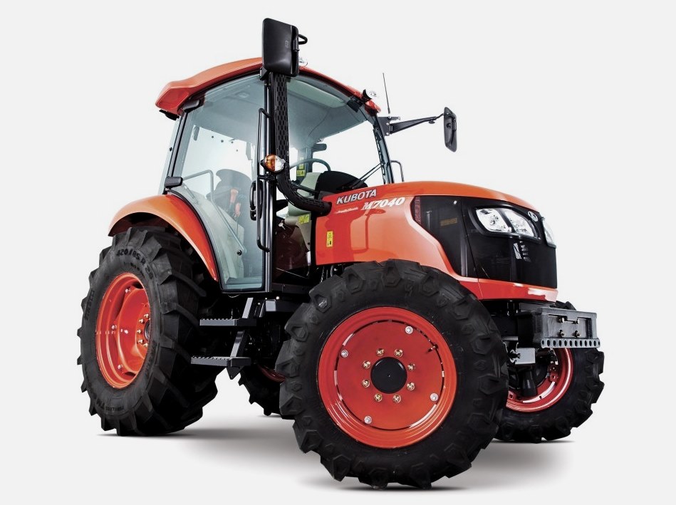 M7040
M7040 M9540
M9540 M9960
M9960 MX5100
 D662
D662 D722
D722 D750
D750 D782
D782 D850
D850 D902
D902 D905
D905 D950
D950 D1005
D1005 D1100
D1100 D1105
D1105 D1503
D1503 D1703
D1703 D1803
D1803 V1200
V1200 V1205
V1205 V1305
V1305 V1505
V1505 V2203
V2203 V2403
V2403 Z482
Z482 Z602
Z602 Z750
Z750 Z1100
Z1100 Z1300
Z1300 B1630
B1630 BF400
BF400 BF400G
 LA181
LA181 LA203
LA203 LA211
LA211 LA243
LA243 LA271
LA271 LA272
LA272 LA301
LA301 LA302
LA302 LA304
LA304 LA340
LA340 LA344
LA344 LA351
LA351 LA352
LA352 LA364
LA364 LA401
LA401 LA402
LA402 LA434
LA434 LA463
LA463 LA481
LA481 LA482
LA482 LA504
LA504 LA513
LA513 LA514
LA514 LA524
LA524 LA525
LA525 LA534
LA534 LA555
LA555 LA680
LA680 LA681
LA681 LA682
LA682 LA703
LA703 LA714
LA714 LA723
LA723 LA724
LA724 LA764
LA764 LA765
LA765 LA805
LA805 LA844
LA844 LA852
LA852 LA853
LA853 LA854
LA854 LA1002
 LA1055
 LA1065
 LA1153
 LA1154
 LA1251
 LA1301S
 LA1353
 LA1403
 LA1601S
 LA1854
 LA1944
 LA1953
 LA2253
 LM2605