________________________________________________________________________________
Kubota B2620, B2630, B2920 - Hydrostatic Transmission
Kubota B2620, B2630, B2920 - Hydrostatic
Transmission Components
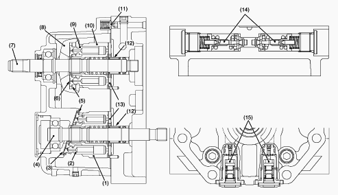
1-Cylinder Block (Motor), 2-Piston, 3-Thrust Collar, 4-Motor Shaft,
5-Retainer Plate, 6-Thrust Collar, 7-Pump Shaft, 8-Variable Swashplate,
9-Piston, 10-Cylinder Block (Pump), 11-Charge Relief Valve, 12-Needle
Bearing, 13-Valve Plate, 14-Check and High Pressure Relief Valve,
15-Neutral Valve
Kubota B2620, B2630, B2920 HST - Control
Linkage
Cruise Control
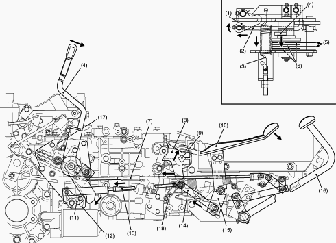
1-Release Lever 1, 2-Cruise Release Rod, 3-Cruise holding Spring,
4-Cruise Control Lever, 5-Friction Plate, 6-Friction Disk, 7-Release
Rod, 8-Neutral Holder, 9-Trunnion Shaft, 10-HST Pedal, 11-Control Lever
Arm 2, 12-Cruise Control Base, 13-Cruise Rod, 14-HST Plate, 15-HST
Lever, 16-Brake Pedal, 17-Return Spring, 18-Return Spring
Cruise control system mainly consists of cruise control lever holding
section and cruise control releasing section. When the cruise control
lever (4) is set to the desired position, the bottom end of the cruise
control lever turns clockwise. The control lever (4) pushes the control
lever arm 2 (11). The control lever arm 2 (11) pulls the cruise rod
(13). The cruise rod (13) pulls the neutral holder (8). The HST plate
(14) is pulled by the cruise rod (13). Since the neutral holder (8)
turns clockwise, the trunnion shaft (9) directly attached to the neutral
holder (8) turns clockwise. On the other hand, since the HST plate (14)
pulls the HST lever (15) and the HST pedal (10). The HST pedal (10) is
turned to the front side. On the other hand, since there is friction
force between the friction plates (5) and the friction disks(6), the
cruise control lever (4) is held at the desired cruise position until
the brake pedals will be depressed by an operator.
Kubota B2620, B2630, B2920 Hydrostatic
Transmission Troubleshooting
System Will Not Operate in Either Direction
Oil level is low - Check oil level or fill oil to proper level.
Speed control pedal linkage defective - Repair linkage.
Charge pressure is too low - Replace oil filter cartridge. Check charge
pressure. Inspect or flush charge relief valve.
Check and high pressure relief valve doesn't move smoothly -
Inspect/replace check and high pressure relief valve.
Neutral valve defective - Inspect or replace neutral valve.
Component parts defective - Replace hydrostatic transmission assembly.
Kubota B2620HST, B2630, B2920 Transmission
Overheat
Low transmission oil level - Fill oil to proper level.
Radiator net clogged - Clean radiator net.
Excessive machine load - Reduce machine load
Improper charge pressure - Check high relief pressure. Replace
transmission oil filter cartridge. Check and high pressure relief valve.
Machine Will not Stop in Neutral Position
Speed control linkage is out of adjustment or sticking - Repair or
replace linkage. Adjust neutral adjuster.
Neutral valve defective - Inspect or replace neutral valve.
System Operates in One Direction Only
Speed control linkage defective - Repair or replace linkage.
Check and high pressure relief valve defective - Replace high pressure
relief valve.
Noise From Front Case
Clutch shaft spline worn - Replace.
Bearing Worn - Replace.
Gear worn or broken - Replace.
Bi-Speed Turn clutch damaged - Replace.
Noise From Front Transmission
Transmission oil insufficient - Refill.
Gear worn or broken - Replace.
Improper backlash between spiral bevel pinon and bevel gear - Adjust.
Improper backlash between differential pinion and differential side gear
- Adjust.
Bearings worn - Replace.
PTO clutch damaged - Repair or replace.
Kubota B2620, B2630, B2920 Tractor -
Transmission Case
Checking Bearing
Hold the inner race, and push and pull the outer race in all directions
to check for wear and roughness. Apply transmission fluid to the
bearing, and hold the inner race. Then, turn the outer race to check
rotation. If there is any defect, replace it.
Clearance between Shift Fork and Shift Gear
Groove
Insert the fork into the shift gear groove and measure the clearance
with a feeler gauge. If the clearance exceeds the allowable limit,
replace it. Clearance between shift fork and shift gear groove - 0.10 to
0.35 mm (0.004 to 0.014 in). Allowable limit - 0.5 mm (0.020 in).
Backlash between Spiral Bevel Pinion and
Spiral Bevel Gear
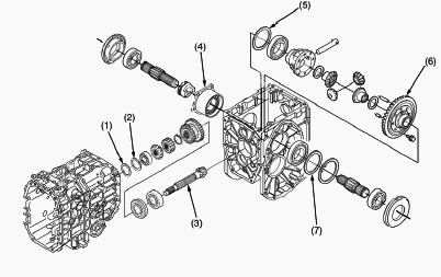
1 - Shim, 2 - Shim, 3 - Spiral Bevel Pinion, 4 - Bearing Holder, 5 -
Shim, 6 - Spiral Bevel Gear, 7 - Shim
Set the dial indicator (lever type) with its finger on the end of spiral
bevel pinion (3). Move the spiral bevel pinion back and forth to each
end and measure the side clearance. If the side clearance exceeds the
factory specifications, adjust with the shims (2) at front end of spiral
bevel pinion. Set the dial indicator (lever type) with its finger on the
tooth surface of bevel gear. Measure the backlash by fixing the spiral
bevel pinion (2) and moving bevel gear (5) by hand. If the backlash
exceeds the factory specifications, adjust with the shims (2), (7) at
bearing holder (4) and differential case. Adjust the backlash properly
by repeating the above procedure. Movement of spiral bevel pinion shaft
at shaft directions - Approx. 0 mm (0 in). Backlash between spiral bevel
pinion and spiral bevel gear - 0.10 to 0.30 mm (0.0039 to 0.0012 in).
Thickness of shims (1) - 0.2 mm (0.008 in.) 1.4 mm (0.055 in.).
Thickness of shims (5), (7) - 0.2 mm (0.008 in.) 0.5 mm (0.020 in.).
Kubota B2620HST, B2630, B2920 Tractor - PTO
Clutch Case
Separating Differential case and PTO Clutch
Case
Remove the transmission case mounting bolts. Separate the transmission
case from the differential case. Remove the PTO brake plate 4 mounting
bolt. Install the PTO brake plate 4 to the transmission case groove
securely.
Bevel Pinion Shafts
Bevel Pinion Shaft 1 - Remove the bevel pinion shaft assembly from the
transmission case. Remove the spacer. Install the spacer to the
transmission case. Install the bevel pinion shaft assembly. Bevel Pinion
Shaft 2 - Gear teeth number are changed by the tractor models. Check the
gear teeth number and assemble the bevel pinion shaft assembly. B2620HST
M/T (4WD/2WD) - 13T / 12T. B2630 (4WD/2WD) - 13T / 15T. B2920 (4WD/2WD)
- 14T / 15T.
Range Gear Shaft Assembly
Remove the cir-clip from the range gear shaft. Remove the spring pin
from the shift arm lever. Remove the range gear shaft assy and the fork
rod from the transmission case.
Range Gear Shaft and Gears
Remove the ball bearing from the rang gear shaft. Remove the 12T gear,
the 18T gear and the 26T gear. Install the range shift arm to the range
shift fork securely. Install the O-rings to the range shift arm.
Front Wheel Drive Shaft
4WD Shaft - Remove the cir-clip from the 4WD shaft. Remove the 4WD gear
from the 4WD shaft. Remove the 4WD shaft with the 26T gear. Remove the
26T gear and the ball bearing. 4WD Shaft Lever - Remove the bolt and the
washer with rubber. Install the 4WD gear to the 4WD shaft. Install the
4WD shaft arm to the 4WD gear. Install the O-rings to the 4WD shift arm.
Rear PTO Shifter and Rear PTO Arm
Remove the rear PTO shifter from the PTO clutch shaft. Remove the spring
pin from the rear PTO arm. Remove the PTO clutch shaft and the PTO
shifter as an assembly. Install the rear PTO arm to the transmission
case. After installing the PTO shifter to the PTO clutch shaft, install
the rear PTO arm to the rear PTO shifter. Install the O-rings to the
rear PTO arm. Install the PTO lever to the rear PTO arm. Install the
spring pin to the rear PTO arm.
Installing PTO Shifter
Install the spring and the ball to the transmission. Push the ball by
finger from the inside of the transmission case. Push the PTO shift arm
ball guide into the transmission case. Push the PTO shift arm ball guide
with the PTO shift arm. Install the PTO cotter to the PTO shift arm.
Align the PTO cotter to the groove of the PTO shifter.
Kubota B2620, B2630, B2920 Transmission -
Checking And Adjusting
Charge Pressure
Remove the lowering speed adjusting knob and the seat under cover.
Remove the plug from reverse port or forward port. If the plug is tight
to remove, warm up the plug by a hair driver etc. Install the adaptor to
reverse port or forward port. Install the cable and low pressure gauge
to the adaptor. Range gear shift position - Neutral. HST pedal -
Neutral. Start the engine and warm the oil before testing. Change the
range gear shift lever to "NEUTRAL" position. Run the engine at the
rated speed. Release the foot from the HST pedal. Read the low pressure
gauge to measure the charge relief pressure. If the measurement is not
same as factory specification, check the charge relief valve and the
related hydraulic components. Charge pressure - 0.4 to 0.6 MPa.
High Pressure Relief Valve Pressure
(Reverse/Forward)
Remove the lowering speed adjusting knob and the seat under cover.
Remove the plug from reverse/forward port. Install the adaptor to
reverse/forward port. Install the cable and high pressure gauge. Range
gear shift position - High. HST pedal - Reverse. Brake pedal -
Depressed. Start the engine and warm the oil before testing. Check to
see that parking brake is applied. Place the range gear shift lever to
"HIGH" position. Run the engine at the rated speed. Depress the rear
side pedal of the HST pedal. Read the high pressure gauge to measure the
high pressure relief valve pressure. If the measurement is not the same
as factory specification, check the check and high pressure relief valve
assembly. Check and high pressure relief valve (Oil temperature at 40 to
60C) - 33.9 to 34.8 MPa.
Cruise Control Adjustment
Before adjusting the cruise control adjustment, adjust the brake pedal
free travel securely. Brake pedal free travel - 30 to 40 mm (1.18 to
1.57 in.) on the pedal. Keep the free travel in the right and the left
brake pedals equal. Check the cruise control is operated properly. The
cruise control lever is returned to “OFF” position when depressing two
brake pedals simultaneously. The cruise control lever is still kept at
“ON” position when depressing one side brake pedal. If the cruise
control is not operated properly as two conditions mentioned above,
adjust the cruise control as follows. Depress the speed control pedal
fully, and set the cruise control lever to “ON” position. Remove the
rear wheel. When the cruise control lever is not returned to “OFF”
position properly by depressing both brake pedals, after connecting both
the left and the right brake pedals. Shorten the release rod until the
cruise control is returned to “OFF” position. When the cruise control
lever is not kept at “ON” position by depressing the one side brake
pedal after disconnecting the brake pedal lock from the right brake
pedal. Lengthen the release rod until the cruise control is kept at “ON”
position. Release rod length (B2620, B2630 / B2930 - 534 mm (21.0 in) /
594 mm (23.4 in).
________________________________________________________________________________
________________________________________________________________________________________
________________________________________________________________________________________
| KUBOTA TRACTORS SPECIFICATIONS |
________________________________________________________________________________________
________________________________________________________________________________________
________________________________________________________________________________________
________________________________________________________________________________________
________________________________________________________________________________________
________________________________________________________________________________________
________________________________________________________________________________________
________________________________________________________________________________________
________________________________________________________________________________________
________________________________________________________________________________________
________________________________________________________________________________________
________________________________________________________________________________________
________________________________________________________________________________________
________________________________________________________________________________________
________________________________________________________________________________________
| KUBOTA ENGINES DATA AND SERVICE SPECS |
________________________________________________________________________________________
________________________________________________________________________________________
________________________________________________________________________________________
________________________________________________________________________________________
________________________________________________________________________________________
| KUBOTA FRONT END LOADERS |
________________________________________________________________________________________
________________________________________________________________________________________
________________________________________________________________________________________
________________________________________________________________________________________
________________________________________________________________________________________
________________________________________________________________________________________
________________________________________________________________________________________
________________________________________________________________________________________
________________________________________________________________________________________
________________________________________________________________________________________
________________________________________________________________________________________
________________________________________________________________________________________
| KUBOTA TRACTORS TROUBLESHOOTING | ||||
| L235 | L2501 | L2550 | L275 | L3110 |
| L3301 | L35 | L3710 | L3901 | L4310 |
| L5030 | M4700 | M5700 | M6040 | M6800 |
| M8200 | M8540 | M9000 | MX5100 | MX5200 |

 SPECIFICATIONS
 LOADERS
 ENGINES
 MAINTENANCE
 PROBLEMS
 B1241
B1241 B1600
B1600 B1700
B1700 B1750
B1750 B21 Backhoe
 B2150
B2150 B2301
B2301 B2320
B2320 B2530
B2530 B26 Backhoe
 B2601
B2601 B2650HSD
 B3030
B3030 B3350
B3350 B6000
B6000 B6100
B6100 B6200
B6200 B7000
B7000 B7001
B7001 B7100HST
 B7200
B7200 B7500
B7500 B7510
B7510 B7800
B7800 B8200HST
 BX1880
 BX2200
 BX2230
 BX2350
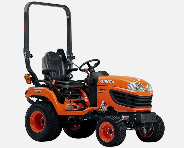 BX2370
 BX23S
BX23S BX25 TLB
 BX2660
 BX2680
 F3680
F3680 L175
L175 L185
L185 L210
L210 L225
L225 L235
L235 L245
L245 L260
L260 L275
L275 L285
L285 L305
L305 GR2120
 L1501
L1501 L2350
L2350 L2550
L2550 L2800
L2800 L3010
L3010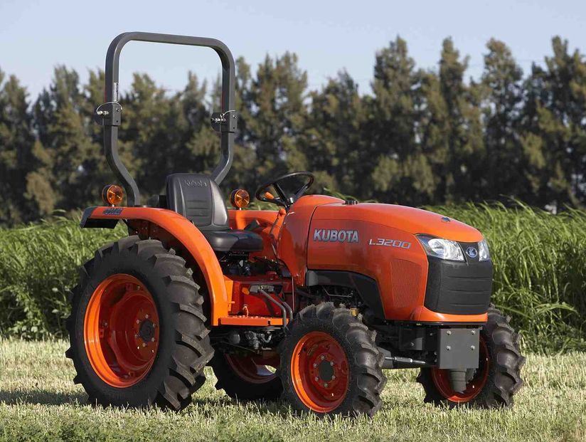 L3200HST
 L3301
L3301 L3560
L3560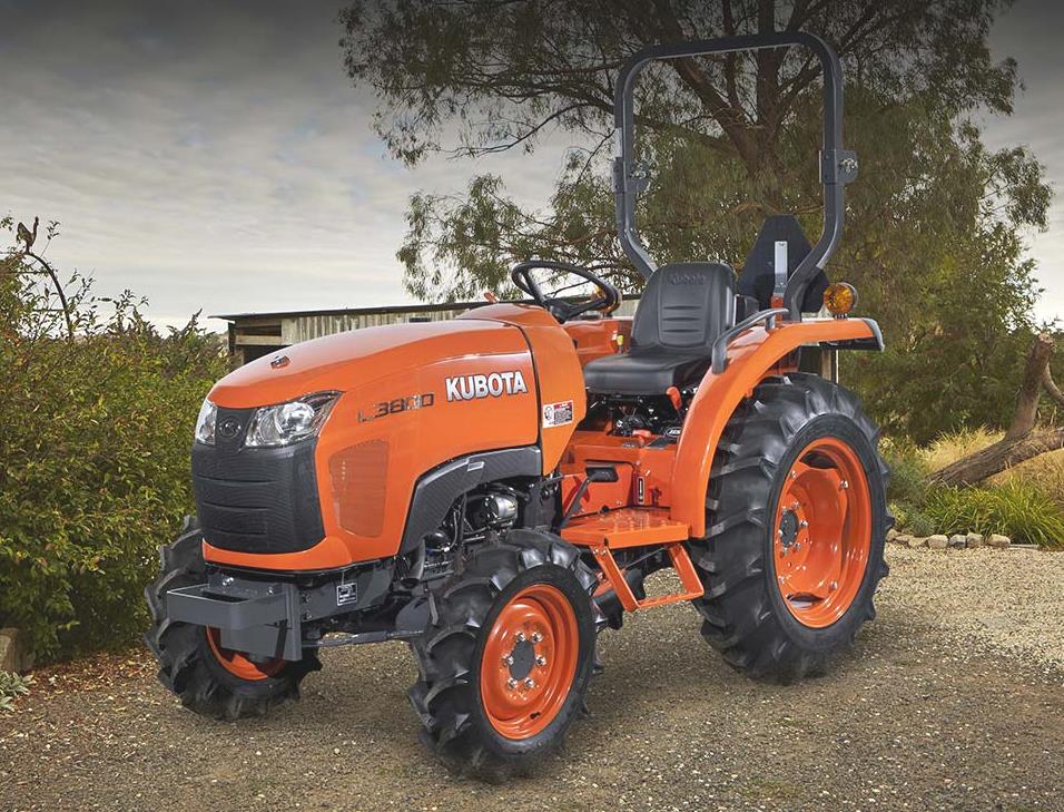 L3800
L3800 L4701
L4701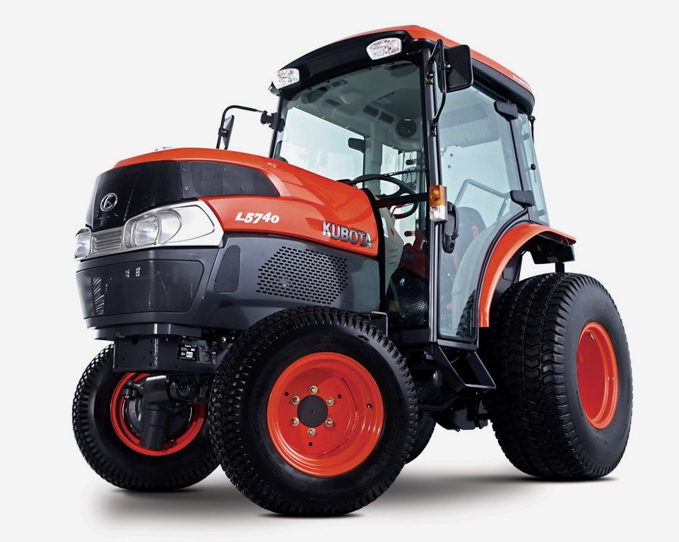 L5740
L5740 M5-091
 M5-111
 M6060
M6060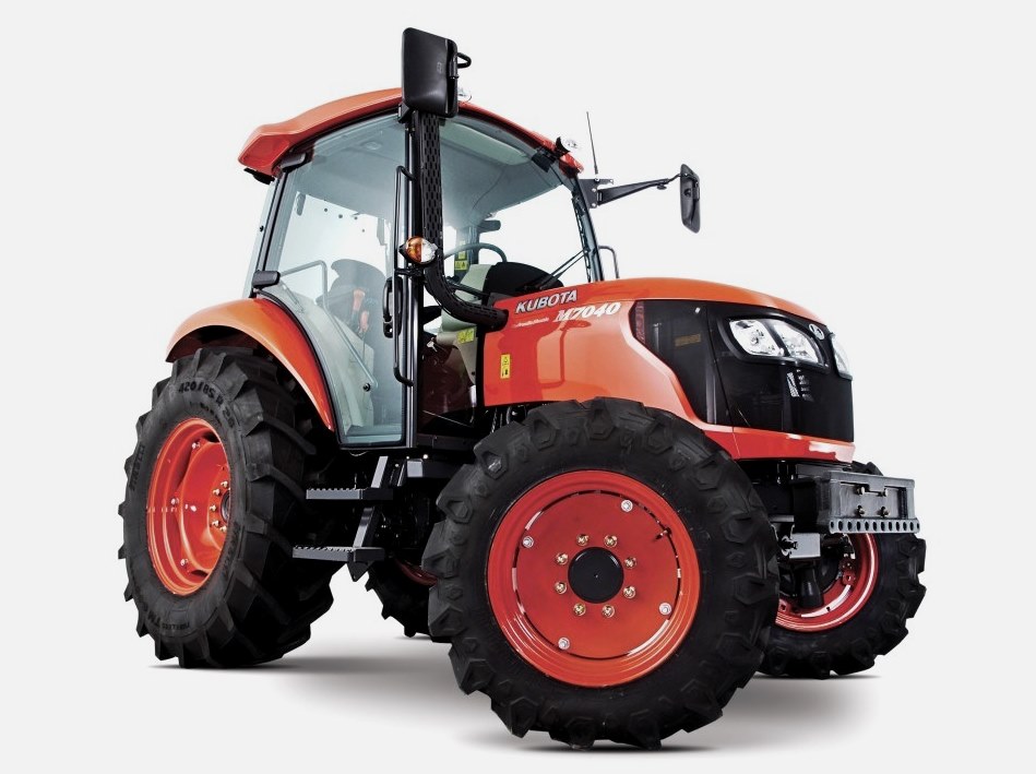 M7040
M7040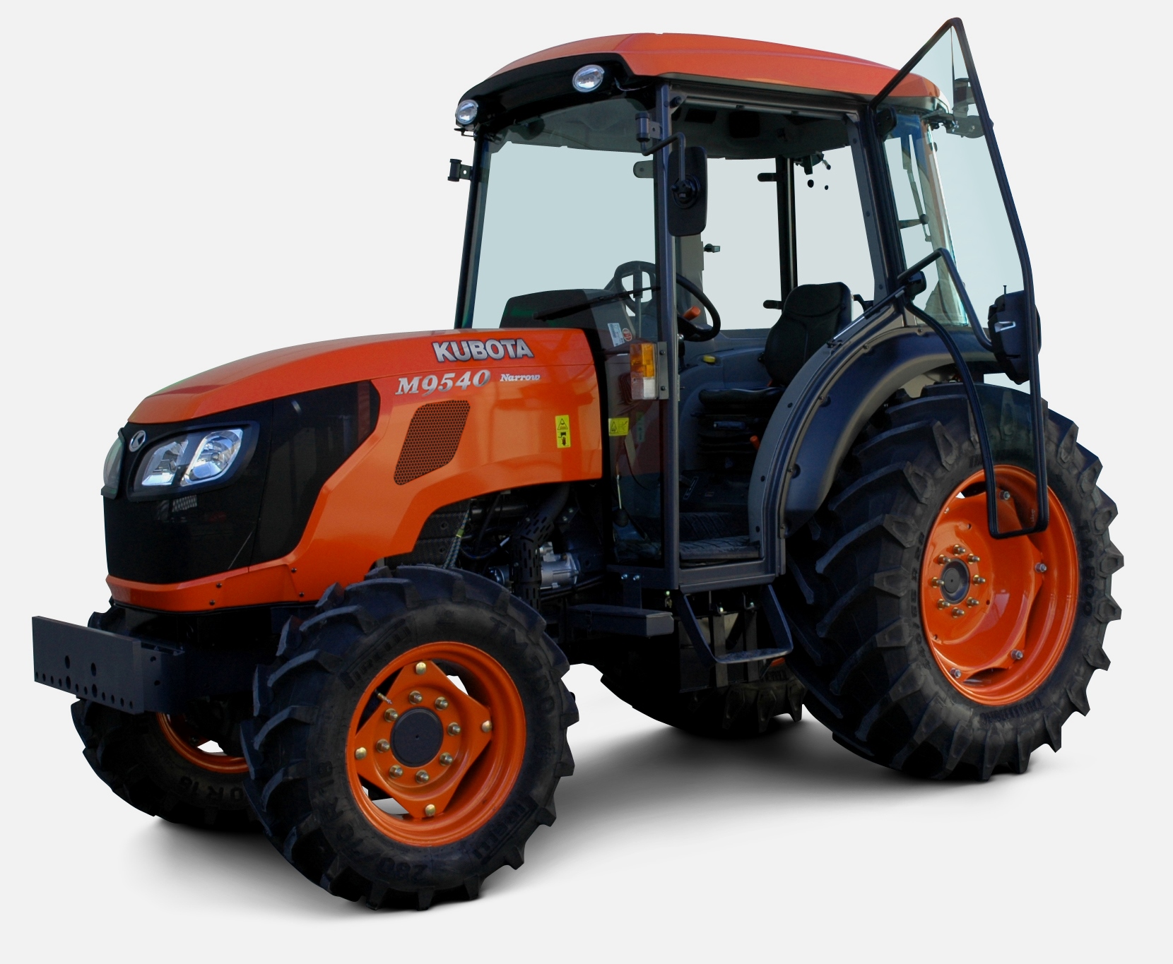 M9540
M9540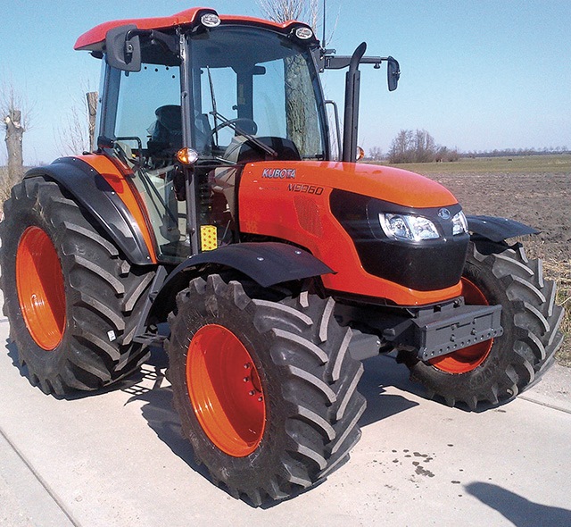 M9960
M9960 MX5100
 D662
D662 D722
D722 D750
D750 D782
D782 D850
D850 D902
D902 D905
D905 D950
D950 D1005
D1005 D1100
D1100 D1105
D1105 D1503
D1503 D1703
D1703 D1803
D1803 V1200
V1200 V1205
V1205 V1305
V1305 V1505
V1505 V2203
V2203 V2403
V2403 Z482
Z482 Z602
Z602 Z750
Z750 Z1100
Z1100 Z1300
Z1300 B1630
B1630 BF400
BF400 BF400G
 LA181
LA181 LA203
LA203 LA211
LA211 LA243
LA243 LA271
LA271 LA272
LA272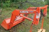 LA301
LA301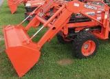 LA302
LA302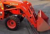 LA304
LA304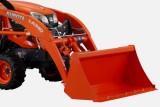 LA340
LA340 LA344
LA344 LA351
LA351 LA352
LA352 LA364
LA364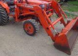 LA401
LA401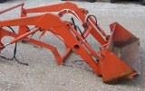 LA402
LA402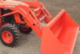 LA434
LA434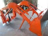 LA463
LA463 LA481
LA481 LA482
LA482 LA504
LA504 LA513
LA513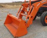 LA514
LA514 LA524
LA524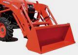 LA525
LA525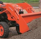 LA534
LA534 LA555
LA555 LA680
LA680 LA681
LA681 LA682
LA682 LA703
LA703 LA714
LA714 LA723
LA723 LA724
LA724 LA764
LA764 LA765
LA765 LA805
LA805 LA844
LA844 LA852
LA852 LA853
LA853 LA854
LA854 LA1002
 LA1055
 LA1065
 LA1153
 LA1154
 LA1251
 LA1301S
 LA1353
 LA1403
 LA1601S
 LA1854
 LA1944
 LA1953
 LA2253
 LM2605