
________________________________________________________________________________
Kubota B2650, B2920 - Engine Service
B2650, B2920 tractors are equipped with a Kubota D1305 3-Cylinder Diesel
Engine.
Kubota B2650, B2920 - Engine Separating
Hood, Side Cover and Battery Cord
Open the hood and remove the front grille. Disconnect the battery
grounding cord. Disconnect the head light connectors and remove the hood
and side covers.
Steering Wheel
Remove the steering wheel cap. Remove the steering wheel mounting nut
and remove the steering wheel with a steering wheel puller. Steering
wheel mounting - 29.4 to 49.0 Nm. Tightening torque nut - 3.0 to 5.0
kgfm.
Meter Panel and Panel Under Cover
Open the meter panel and disconnect the meter panel connector and
hour-meter cable. Then remove the meter panel. Disconnect the
combination switch connector, main switch connector and hazard switch
connector. Tap out the spring pin and remove the hand accelerator lever.
Remove the panel under cover.
Fuel Tank
Disconnect the fuel hose at the fuel filter side, then drain fuel
completely. Remove the fuel tank frame stay. Disconnect the hazard unit,
starter relay and regulator connectors and remove the lead wire for fuel
gauge. Remove the fuse box. Disconnect the overflow hoses of fuel line.
Remove the tank frame with fuel tank. Disconnect the hydraulic pipes and
remove the battery stay with oil cooler. Disconnect the 2P connector and
remove the engine stop solenoid.
Propeller Shaft Cover and Coupling
Loosen the clamp and slide the propeller shaft cover to the rear. Tap
out the spring pin and then slide the coupling to the rear. Apply grease
to the splines of the propeller shaft and coupling.
Universal Joint and Bearing Holder
Loosen the Clamp and slide the universal joint cover to the rear. Tap
out the spring pins and then slide the universal joint to the rear.
Remove the bearing holder with propeller shaft and universal joint.
Apply grease to the splines of the propeller shaft and universal joint.
When inserting the spring pins, face their splits in the direction
parallel to the universal joint.
Drag Link
Remove the cotter pin and loosen the slotted nut. Disconnect the drag
link with a pitman arm puller from the knuckle arm. Do not loosen the
slotted nut to align the hole.
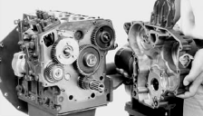
Separating the Kubota D1305 Engine from Clutch
Housing
Disconnect the three point hitch delivery pipe and suction hose.
Disconnect the glow plug lead wire and thermo sensor lead wire. And then
disconnect the connector for dynamo and starter motor lead wire. Place
the jack under the center frame. Hoist the engine by the chain at the
engine hook. Remove the engine mounting screws and separate the engine
from the clutch housing. Apply liquid gasket to joint face of the engine
and clutch housing.
Separating Front Axle Assembly
Disconnect the radiator hoses. Remove the muffler pipe. Hoist the engine
by the chain at the engine hook. Remove the front axle frame mounting
screws and separate the front axle assembly from the engine. Clutch
cover mounting - 23.5 to 27.5 Nm. Tightening torque screw - 2.4 to 2.8
kgfm.
Outer Parts
Remove the hydraulic pump. Remove the clutch assembly. Direct the
shorter end of the clutch disc boss toward the flywheel. Apply
molybdenum disulphide to the splines of clutch disc boss. Insert the
pressure plate noting the position of straight pins. Be sure to align
the center of disc and flywheel by inserting the clutch center tool. Do
not allow grease and oil on the clutch disc facing.
Kubota B2650, B2920 - Engine Maintenance
Changing Engine Oil
Start and warm up the engine for approx. 5 minutes. Place an oil pan
underneath the engine. To drain the used oil, remove the drain plug at
the bottom of the engine and drain the oil completely. Screw in the
drain plug. Fill new oil up to upper line on the dipstick. When using an
oil of different manufacture or viscosity from the previous one, remove
all of the old oil. Never mix two different types of oil.
Replacing Engine Oil Filter Cartridge
Remove the oil filter cartridge with the filter wrench. Apply a slight
coat of oil onto the cartridge gasket. To install the new cartridge,
screw it in by hand. Over tightening may cause deformation of rubber
gasket. After the new cartridge has been replaced, the engine oil
normally decrease a little. Thus see that the engine oil does not leak
through the seal and be sure to read the oil level on the dipstick.
Then, replenish the engine oil up to the specified level.
Kubota D1305 - Cleaning Air Cleaner Element
Remove the air cleaner cover and primary element. Clean the primary
element if: When dry dust adheres to the element, blow compressed air
from the inside turning the element. Pressure of compressed air must be
under 686 kPa (7 kgf/cm2, 99 psi). When carbon or oil adheres to the
element, soak the element in detergent for 15 minutes then wash it
several times in water, rinse with clean water and dry it naturally.
After element is fully dried, inspect inside of the element with a light
and check if it is damaged or not. When replacing the air cleaner
primary element, replace the secondary element as well: Once a year or
after every six times of cleaning, whichever comes first.
Cleaning Fuel Filter
This job should not be done in the field, but in a clean place. Loosen
and remove the fuel filter bowl, and rinse the inside with kerosene.
Take out the filter element and dip it in the kerosene to rinse. After
cleaning, reassemble the fuel filter, keeping out dust and dirt. Bleed
the fuel system. When the fuel filter bowl has been removed, fuel stops
flowing from the fuel tank. If the fuel tank is almost full, however,
the fuel will flow back from the fuel return pipe to the fuel filter.
Before the above checking, make sure the fuel tank is less than
half-full.
Kubota B2650, B2920 Engine - Cylinder Head and
Valves
Dynamo, Fan Belt and Muffler
Remove the dynamo and fan belt. Remove the cooling fan and fan pulley.
Remove the air cleaner assembly and stay. Remove the muffler. Check to
see that there are no cracks on the belt surface. After reassembling the
fan belt, be sure to adjust the fan belt tension.
Cylinder Head Cover and Injection Pipes
Remove the head cover cap nuts. Remove the cylinder head cover. Loosen
the screws on the pipe clamps. Detach the injection pipes. Check to see
if the cylinder head cover gasket is not defective. Sent compressed air
into the pipes to blowout dust. Then, reassemble the pipes in the
reverse order.
Kubota B2650, B2920 - Nozzle Holder Assembly
and Glow Plug
Remove the overflow pipe assembly. Remove the nozzle holder assemblies.
Remove the copper gasket and heat seal. Remove the lead from the glow
plugs. Remove the glow plugs. Replace the copper gasket and heat seal
with new one.
Nozzle Heat Seal Service Removal Procedure
Use a plus (phillips head) screw driver that has a Dia. which is bigger
than the heat seal hole (Approx. 6 mm) 1/4 in. Drive screw driver
lightly into the heat seal hole. Turn screw driver three or four times
each way. While turning the screw driver, slowly pull the heat seal out
together with the copper gasket. If the heat seal drops, repeat the
above procedure. Heat seal and copper gasket must be changed when the
injection nozzle is removed for cleaning or for service.
Rocker Arm and Push Rod
Remove the rocker arm bracket nuts. Detach the rocker arm assembly.
Remove the push rods. When putting the push rods onto the tappets, check
to see if their ends are properly engaged with the grooves. After
installing the rocker arm, be sure to adjust the valve clearance. Rocker
arm bracket nut tightening torque - 21.6 to 26.5 Nm (15.9 to 19.5
ft-Ibs).
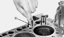
Kubota D1305 Cylinder Head
Loosen the pipe clamp, and remove the water return pipe. Remove the
cylinder head screw in the order. Lift up the cylinder head to detach.
Remove the cylinder head gasket and O-ring. Replace the cylinder head
gasket with a new one. Securely fit the O-ring to the pipe pin. Tighten
the cylinder head screws after applying sufficient oil. Tighten the
cylinder head screws gradually screw in the order. Tighten them
uniformly, or the head may deform in the long run. Retighten the
cylinder head screws after running the engine for 30 minutes. Cylinder
head screw tightening torque - 63.7 to 68.6 Nm (47.0 to 50.6 ft-Ibs).
Tappets
Remove the tappets from the crankcase. Visually check the contact
between tappets and cams for proper rotation. If defect is found,
replace tappets. Before installing the tappets, apply engine oil thinly
around them. Do not change the combination of tappet and tappet guide.
Valves
Remove the valve caps. Remove the valve spring collet, pushing the valve
spring retainer by valve spring replacer. Remove the valve spring
retainer, valve spring and valve stem seal. Remove the valve. Wash the
valve stem and valve guide hole, and apply engine oil sufficiently.
After installing the valve spring collets, lightly tap the stem to
assure proper fit with a plastic hammer.
Kubota B2650, B2920 - Timing Gears, Camshaft
and Fuel Camshaft
Fan Drive Pulley
Set the stopper to the flywheel. Remove the fan drive pulley screw. Draw
out the fan drive pulley with a puller. Fan drive pulley retaining
tightening torque 235.4 to 245.2 Nm (173.6 to 180.8 ft-Ibs).
Fuel Pump, Hour Meter Gear Case and Water Pump
Remove the fuel pump. Remove the hour meter gear case. Remove the water
pump flange. Before installing the hour meter gear case gasket, apply
liquid gasket to the both side.
Gear Case
Remove the gear case. Remove the crankshaft collar and O-rings. Replace
the gear case gasket with a new one. Be sure to set four O-rings inside
the gear case and the O-ring on the crankshaft. Apply a thin film of
engine oil to the oil seal, and install it, noting the lip come off.
Length of the gear case mounting screws.
Speed Control Plate
Remove the speed control plate and governor lever from the governor
springs 1 and 2. Securely catch the governor springs 1 and 2 on the
governor lever. Apply a liquid gasket to both sides of the speed control
plate gasket.
Injection Pump
Remove the injection pump mounting screws and nuts. Align the control
rack pin with the notch on the crankcase, then remove the injection
pump. Remove the injection pump timing shims. In principle, the
injection pump should not be disassembled. Securely fit the control rack
pin to the grooves of the fork lever and thrust lever. The sealant is
applied to both sides of the shim (soft metal gasket shim). The liquid
gasket is not required for assembling. Addition or reduction of shims
(0.05 mm, 0.0020 in.) delays or advances the injection timing by approx.
0.0087 rad. (0.5°). In disassembling and replacing, be sure to use the
same number of new shims with the same thickness.
Kubota B2650, B2920 - Fuel Camshaft
Remove the fuel camshaft stopper. Draw out the fuel camshaft and
injection pump gear. Remove the fuel feed pump cam from the injection
pump gear. Apply engine oil thinly to the fuel camshaft before
installation. Check to see each aligning marks of cam and gear are
aligned.
Governor Shaft
Remove the external snap ring from the governor shaft. Pull out the
governor shaft. Make sure assembling the external snap ring of the
governor shaft. Check the governor shaft for smooth rotation. When
replacing the ball bearing of governor shaft, securely fit the ball
bearing to the crankcase, apply an adhesive to the set screw, and fasten
the screw until its tapered part contacts the circumferential end of the
ball bearing.
Fork Lever
Remove the start spring. Remove the fork lever shaft cover. Pull out the
fork lever shaft, and remove the spacer, bearing, fork levers 1 and 2.
Apply a liquid gasket to the both sides of the fork lever shaft cover,
and fit the fork lever shaft cover with the "UP" mark facing upwards.
Securely fit the start spring.
Camshaft and Idle Gear 1
Remove the external snap ring, and then remove the idle gear 1. Remove
the camshaft stopper mounting screw, and pull out the camshaft. When
installing the idle gear 1, be sure to align the alignment marks on the
gears. Securely fit the external snap ring and stopper.
Kubota B2650, B2920 - Piston and Connecting
Rod
Oil Pan and Oil Strainer
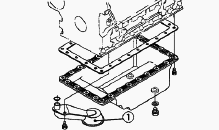
Remove the oil pan mounting screws. Remove the oil pan by lightly
tapping the rim of the pan with a wooden hammer. Remove the oil
strainer. After cleaning the oil strainer, check to see that the filter
mesh in clean, and install it. Visually check the O-ring, apply engine
oil, and install it. Securely fit the O-ring to the oil strainer. Apply
a liquid gasket to the oil pan. To avoid uneven tightening, tighten oil
pan mounting screws in diagonal order from the center. Scrape off the
old adhesive completely. Wipe the sealing surface clean using waste
cloth soaked with gasoline. Now apply new adhesive 3 to 5 mm (0.12 to
0.20 in.) thick all over the contact surface. Apply the adhesive also on
the center of the flange as well as on the inner wall of each bolt hole.
Cut the nozzle of the "liquid gasket" container at its second notch.
Apply "liquid gasket" about 5 mm (0.20 in.) thick. Within 20 minutes
after the application of fluid sealant, reassemble the components. Wait
then for about 30 minutes, and pour oil in the crankcase.
Connecting Rod Cap
Remove the connecting rod caps. Align the marks (a) with each other.
(Face the marks toward the injection pump.). Apply engine oil to the
connecting rod screws and lightly screw it in by hand, then tighten it
to the specified torque. If the connecting rod screw won't be screwed in
smoothly, clean the threads. If the connecting rod screw is still hard
to screw in, replace it. Connecting rod screw tightening torque - 41.2
to 46.1 Nm (30.3 to 33.9 ft-Ibs).
Pistons
Turn the flywheel and bring the piston to top dead center. Draw out the
piston upward by lightly tapping it from the bottom of the crankcase
with the grip of a hammer. Draw out the other piston in the same method
as above. Before inserting the piston into the cylinder, apply enough
engine oil to the piston. When inserting the piston into the cylinder,
face the mark on the connecting rod to the injection pump.
Piston Ring and Connecting Rod
Remove the piston rings using a piston ring tool. Remove the piston pin,
and separate the connecting rod from the piston. When installing the
ring, assemble the rings so that the manufacturer's mark near the gap
faces the top of the piston. When installing the oil ring onto the
piston, place the expander joint on the opposite side of the oil ring
gap. Apply engine oil to the piston pin. When installing the connecting
rod to the piston, immerse the piston in 80C oil for 10 to 15 minutes
and insert the piston pin to the piston. When installing the connecting
rod to the piston, align the mark on the connecting rod to the arrow's
direction of casting mark on the piston. Mark the same number on the
connecting rod and the piston so as not to change the combination.
Kubota B2650, B2920 - Engine Crankshaft
Flywheel
Fit the stopper to the flywheel. Remove the flywheel screws and then
remove the flywheel. Fit the flywheel giving care to the position of the
knock pin. Apply engine oil to the threads and the undercut surface of
the flywheel bolt and fit the bolt. Flywheel screw tightening torque
53.9 to 58.8 Nm (39.8 to 43.4 ft-Ibs).
Bearing Case Cover
Remove the bearing case cover mounting screws. First, remove inside
screws and then outside screws. Screw two removed screws into the screw
hole of bearing case cover to remove it. Fit the bearing case gasket and
the bearing case cover gasket with correct directions. Install the
bearing case cover to position the casting mark "UP" on it upward. Apply
engine oil to the oil seal lip and take care that it is not rolled when
installing. Tighten the bearing case cover mounting screws with even
force on the diagonal line.
Kubota D1305 - Crankshaft Assembly
Remove the main bearing case screw. Pull out the crankshaft assembly.
Take care to protect crankshaft bearing from scratches caused by the
crank gear, etc. (Wrap the gear in vinyl tape, etc.). Clean the oil
passage of the crankshaft with compressed air. Apply oil to the main
bearing case screw. Install the crankshaft assembly, aligning the screw
hole of main bearing case with the screw hole of crankcase. Clean the
oil passage of the crankshaft with compressed air. Main bearing case
screw tightening torque - 49.0 to 53.9 Nm (36.2 to 39.8 ft-Ibs).
Main Bearing Case Assembly
Remove the two main bearing case screws 1, and remove the main bearing
case assembly, being careful with the thrust bearing and crankshaft
bearing 2. Remove the main bearing case assembly 1, 2 and 3 as above.
Clean the oil passage in the main bearing case. Apply clean engine oil
on the bearings. Install the main bearing case assemblies in the
original positions. Since diameters of main bearing case vary, install
them in order of makings from the gear case side. Match the alignment
numbers on the main bearing case. When installing the main bearing case
1, 2, and 3, face the mark "FLYWHEEL" to the flywheel. Install the
thrust bearing with its oil groove facing outward. Confirm that the main
bearing case moves smoothly after tightening the main bearing case screw
1 to 29.4 to 34.3 Nm.
________________________________________________________________________________
________________________________________________________________________________________
 SPECIFICATIONS
 LOADERS
 ENGINES
 INSTRUCTIONS
 PROBLEMS
________________________________________________________________________________________
 B2320
B2320 B2630
B2630 B2920
B2920 B3300SU
 BX2360
________________________________________________________________________________________
 L245
L245 L260
L260 L275
L275 L285
L285 L305
L305________________________________________________________________________________________
________________________________________________________________________________________
 D662
D662 D722
D722 D750
D750 D782
D782 D850
D850________________________________________________________________________________________
 LA302
LA302 LA304
LA304 LA340
LA340 LA344
LA344 LA351
LA351________________________________________________________________________________________
 BX2660
 L2501
L2501 L3240
L3240 L3540
L3540 L3940
L3940________________________________________________________________________________________
 D902
D902 D905
D905 D950
D950 D1005
D1005 D1100
D1100________________________________________________________________________________________
________________________________________________________________________________________
 B1630
B1630 BF400
BF400 BF400G
 LA181
LA181 LA203
LA203________________________________________________________________________________________
 LA211
LA211 LA243
LA243 LA271
LA271 LA272
LA272 LA301
LA301________________________________________________________________________________________
 L175
L175 L185
L185 L210
L210 L225
L225 L235
L235________________________________________________________________________________________
 D1105
D1105 D1503
D1503 D1703
D1703 D1803
D1803 V1200
V1200________________________________________________________________________________________
 L4400
L4400 L4600
L4600 L5040
L5040 L5740
L5740 MX4700
________________________________________________________________________________________
 LA352
LA352 LA364
LA364 LA401
LA401 LA402
LA402 LA403
LA403________________________________________________________________________________________
 LA434
LA434 LA463
LA463 LA481
LA481 LA482
LA482 LA504
LA504________________________________________________________________________________________
 V1205
V1205 V1305
V1305 V1505
V1505 V2203
V2203 V2403
V2403________________________________________________________________________________________
 B2710
B2710 BX23S
BX23S B3350
B3350 BX1880
 L4701
L4701________________________________________________________________________________________
 LA513
LA513 LA514
LA514 LA524
LA524 LA525
LA525 LA534
LA534________________________________________________________________________________________
 LA555
LA555 LA680
LA680 LA681
LA681 LA682
LA682 LA703
LA703________________________________________________________________________________________
 Z482
Z482 Z602
Z602 Z750
Z750 Z1100
Z1100 Z1300
Z1300________________________________________________________________________________________
 M100GX
 M135GX
 M6040
M6040 M8540
M8540 M95X
M95X________________________________________________________________________________________
 LA714
LA714 LA723
LA723 LA724
LA724 LA764
LA764 LA765
LA765________________________________________________________________________________________
 LA805
LA805 LA844
LA844 LA852
LA852 LA853
LA853 LA854
LA854________________________________________________________________________________________
 M5-091
 BX2680
 MX5200
 BX2380
 L3901
L3901________________________________________________________________________________________
 LA1002
 LA1055
 LA1065
 LA1153
 LA1154
________________________________________________________________________________________
 LA1251
 LA1301S
 LA1353
 LA1403
 LA1601S
________________________________________________________________________________________
 LA1854
 LA1944
 LA1953
 LA2253
 LM2605