
________________________________________________________________________________
Kubota B3030, B3350, B3150, B7800 - Engine Maintenance
B3030, B3350, B3150, B7800 tractors are equipped with a Kubota V1505
4-cylinder diesel engine.
Kubota B3030, B3350, B3150, B7800 - Separating
Engine
Bonnet, Front Grille, Side Covers and ROPS
Open the bonnet. Remove the pin and the plain washer. Remove the wiring
harness from the bonnet. Remove the hood. Remove the front grille and
the side covers. Remove the ROPS. Install the bush to the bonnet
securely. Install the hood. Don't damage the bonnet when installing it.
Battery
Disconnect the battery negative cable first. Disconnect the battery
positive cable second. Remove the battery. Remove the front hitch.
Hydraulic Hoses from Power Steering Cylinder
Disconnect the hydraulic hoses from the power steering cylinder.
Removing the snap pin and disconnect the bi-speed rod.
Steering Wheel, Meter Panel, Shuttle Lever and
Panel Lower Cover
Remove the steering wheel cap. Remove the steering wheel mounting nut.
Remove the steering wheel with a steering wheel puller. Remove the
accelerator lever grip and the steering boot. Disconnect the hour meter
cable and wiring harness connectors. Remove the meter panel not to
damage with the steering shaft. Remove the shuttle lever. Remove the
panel lower cover. Tighten the steering wheel mounting nut securely.
Fuel Tank
Disconnect the leads from the fuel tank. Disconnect the overflow hoses
from the fuel tank. Remove the shutter plate and the fuel tank.
Key Stop Solenoid and Hydraulic Delivery Pipe
Remove the key stop solenoid connector. Remove the engine stop solenoid
using a small size ratchet handle, the extension joint, the universal
joint and the thinner socket (10 mm). Remove the hydraulic delivery pipe
mounting nuts. Slide the hydraulic delivery pipe. Loosen the hose band.
Disconnect the suction hose from the hydraulic pump. Apply the liquid
gasket to the joint face of the key stop solenoid and the engine.
Final Separating Engine
Reinstall the rear tires. Support the transmission with a disassembling
stand. Hook the engine with a hoist. Place the disassembling stand under
the main frame. Disconnect the power steering hoses. Loose the hydraulic
inlet hose band. Disconnect the hydraulic inlet hose from the hydraulic
pump. Disconnect the hydraulic delivery pipe from the hydraulic pump.
Disconnect the wiring leads from the alternator, the engine oil pressure
switch and the starter motor. Disconnect the wiring harness and the
power steering hoses from the engine body. Remove the docking bolts
between the engine and the front case. Align the spline between the
front wheel drive shaft and the universal joint securely. Tighten the
docking bolts between the engine and the front case securely. Remove the
exhaust pipe. Disconnect the radiator hoses. Remove the front axle frame
mounting bolts. Separate the front axle from the engine.
Kubota B3030, B3350, B3150, B7800 - Engine
Components
Compression Pressure
Run the engine until it is warmed up. Stop the engine and disconnect the
2P connector from the engine stop solenoid. Remove the air cleaner, the
muffler and all injection nozzles. Set a compression tester with the
adaptor to the nozzle hole. While cranking the engine with the starter,
measure the compression pressure. Repeat steps 4 through 6 for each
cylinder. If the measurement is below the allowable limit, apply a small
amount of oil to the cylinder wall through the nozzle hole and measure
the compression pressure again. If the compression pressure is still
less than the allowable limit, check the top clearance, valve and
cylinder head. If the compression pressure increases after applying oil,
check the cylinder wall and piston rings. Check the compression pressure
with the specified valve clearance. Always use a fully charged battery
for performing this test. Variances in cylinder compression values
should be under 10 0/0. Compression pressure - 2.84 to 3.24 MPa (412 to
469 psi). Allowable limit - 2.26 MPa (327 psi).
Top Clearance
Remove the cylinder head. (Do not attempt to remove the cylinder head
gasket.). Move the piston up, and stick a strip of fuse (1.5 mm dia./
0.059 in. dia.), 5 to 7 mm long / 0.197 to 0.276 in. long) on the piston
head at three positions with grease so as to avoid the intake and
exhaust valves and the combustion chamber ports. Lower the piston, and
install the cylinder head and tighten the cylinder head screws to the
specified torque. Turn the crankshaft until the piston exceeds its top
dead center. Remove the cylinder head, and measure the thickness of the
squeezed fuses. If the measurement is not within the factory
specifications, check the oil clearance between the crankpin and
crankpin bearing and between the piston pin and small end bushing. After
checking the top clearance, be sure to assemble the cylinder head with a
new cylinder head gasket. Top clearance - 0.55 to 0.70 mm (0.0217 to
0.0276 in).
Valve Clearance
Valve clearance must be checked and adjusted when engine is cold. Remove
the head cover, the glow plugs and the timing window cover on the clutch
housing. Align the "1TC" mark line on the flywheel and center of timing
window so that the No. 1 piston comes to the compression or overlap top
dead center. Check the following valve clearance marked using a feeler
gauge. If the clearance is not within the factory specifications, adjust
with the adjusting screw. Valve Clearance - 0.145 to 0.185 mm (0.0057 to
0.0073 in).
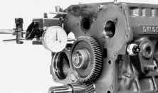
Kubota V1505 - Timing Gear
Set a dial indicator (lever type) with its tip on the gear tooth. Move
the gear to measure the backlash, holding its mating gear. If the
backlash exceeds the allowable limit, check the oil clearance of the
shafts and the gear. If the oil clearance is proper, replace the gear.
Backlash between idle gear 1 and crank gear 0.032 to 0.115 mm / 0.00120
to 0.00453 in.
Backlash between idle gear 1 and cam gear 0.036 to 0.114 mm / 0.00142 to
0.00449 in.
Backlash between idle gear 1 and injection pump gear 0.034 to 0.116 mm /
0.00134 to 0.00457 in.
Backlash between idle gear 1 and idle gear 2 0.033 to 0.117 mm / 0.0013
to 0.0046 in.
Backlash between idle gear 2 and governor gear 0.030 to 0.117 mm /
0.00118 to 0.00461 in.
Idle Gear Side Clearance - Set a dial indicator with its tip on the idle
gear. Measure the side clearance by moving the idle gear to the front
and rear. If the measurement exceeds the allowable limit, replace the
idle gear collar. Idle gear side clearance - 0.050 to 0.150 mm (0.0020
to 0.0059 in). Idle Gear 2 Side Clearance - Set a dial indicator with
its tip on the idle gear. Measure the side clearance by moving the idle
gear to the front and rear. If the measurement exceeds the allowable
limit, replace the idle gear collar. Idle gear 2 side clearance - 0.20
to 0.51 mm (0.0079 to 0.0201 in).
Cylinder Wear
Measure the I.D. of the cylinder at the six positions with a cylinder
gauge to find the maximum and minimum I.D.'s. Get the difference
(Maximum wear) between the maximum and the minimum I.D.'s. If the wear
exceeds the allowable limit, bore and hone to the oversize dimension.
Visually check the cylinder wall for scratches. If deep scratches are
found, the cylinder should be bored. Cylinder liner I.D. - 78.000 to
78.019 mm / 3.01086 to 3.07161 in.
Kubota B3030, B3350, B3150, B7800 -
Lubricating System
Changing Engine Oil
Start and warm up the engine for approx. 5 minutes. Place an oil pan
underneath the engine. To drain the used oil, remove the drain plug at
the bottom of the engine and drain the oil completely. Screw in the
drain plug. Fill new oil up to upper line on the dipstick. When using an
oil of different manufacture or viscosity from the previous one, remove
all of the old oil. Never mix two different types of oil.
Replacing Engine Oil Filter Cartridge
Remove the oil filter cartridge with the filter wrench. Apply a slight
coat of oil onto the cartridge gasket. To install the new cartridge,
screw it in by hand. Over tightening may cause deformation of rubber
gasket. After the new cartridge has been replaced, the engine oil
normally decrease a little. Thus see that the engine oil does not leak
through the seal and be sure to read the oil level on the dipstick.
Then, replenish the engine oil up to the specified level.
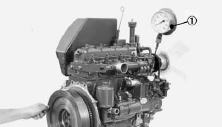
Engine Oil Pressure
Remove the engine oil pressure switch, and set a oil pressure tester.
Start the engine. After warming up, measure the oil pressure of both
idling and rated speeds.
Oil Pump
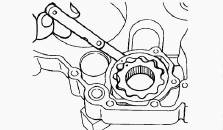
Rotor Lobe Clearance - Measure the clearance between lobes of the inner
rotor and the outer rotor with a feeler gauge. If the clearance exceeds
the factory specifications, replace the oil pump rotor assembly.
Clearance between Outer Rotor and Pump Body - Measure the clearance
between the outer rotor and the pump body with a feeler gauge. If the
clearance exceeds the factory specifications, replace the oil pump rotor
assembly. Clearance between Rotor and Cover - Put a strip of plastigage
onto the rotor face with grease. Install the cover and tighten the
screws. Remove the cover carefully, and measure the amount of the
flattening with the scale and get the clearance. If the clearance
exceeds the factory specifications, replace oil pump rotor assembly.
Kubota B3030, B3350, B3150, B7800 - Cooling
System
Fan Belt
Fan Belt Tension - Measure the deflection, depressing the belt halfway
between the fan drive pulley and alternator pulley at specified force
(98 N, 10 kgf, 22 Ibs). If the measurement is not within the factory
specifications, loosen the alternator mounting screws and relocate the
alternator to adjust. Deflection - 7 to 9 mm / 0.28 to 0.35 in. Fan Belt
Damage and Wear - Check the fan belt for damage. If the fan belt is
damaged, replace it. Check if the fan belt is worn and sunk in the
pulley groove. If the fan belt is nearly worn out and deeply sunk in the
pulley groove, replace it.
Radiator
Radiator Water Leakage - Pour a specified amount of water into the
radiator. Set a radiator tester and raise the water pressure to the
specified pressure. Check the radiator for water leaks. For water leak
from the pinhole, replace the radiator or repair with the radiator
cement. When water leak is excessive, replace the radiator. Radiator Cap
Air Leakage - Set a radiator tester on the radiator cap. Apply the
specified pressure (88 kPa, 0.9 kgf/cm2, 13 psi), and measure the time
for the pressure to fall to 59 kPa (0.6 kgf/cm2, 9 psi). If the
measurement is less than the factory specification, replace the radiator
cap. Checking Radiator Hose and Hose Clamp - Check to see if radiator
hoses are properly fixed every 200 hours of operation or six months,
whichever comes first. If hose clamps are loose or water leaks, tighten
bands securely. Replace hoses and tighten hose clamps securely, if
radiator hoses are swollen, hardened or cracked. Replace hoses and hose
clamps every 2 years or earlier if checked and found that hoses are
swollen, hardened or cracked.
Flush Cooling System and Changing Coolant
Stop the engine and let cool down. To drain the coolant, open the
radiator drain cock, and remove radiator cap. The radiator cap must be
removed to completely drain the coolant. After all coolant is drained,
close the drain plug. Fill with clean water and cooling system cleaner.
Follow directions of the cleaner instruction. After flushing, fill with
clean water and anti-freeze until the coolant level is just below the
port. Start and operate the engine for few minutes. Stop the engine.
Check coolant level and add coolant if necessary. Install the radiator
cap securely.
Thermostat Assembly
Remove the thermostat cover mounting screws, and remove the thermostat
cover. Remove the thermostat assembly. Apply a liquid gasket only at the
thermostat cover side of the gasket.
Water Pump Assembly
Loosen the alternator mounting bolts, and remove the fan belt. Remove
the fan and fan pulley. Remove the water pump assembly from the gear
case cover. Remove the water pump flange. Press out the water pump shaft
with the impeller on it. Remove the impeller from the water pump shaft.
Remove the mechanical seal. Apply a liquid gasket to the both sides of
gasket. Replace the mechanical seal with new one.
Kubota B3030, B3350, B3150, B7800 - Fuel
System
Cleaning Air Cleaner Element
Remove the air cleaner cover and primary element. Clean the primary
element if: When dry dust adheres to the element, blow compressed air
from the inside turning the element. Pressure of compressed air must be
under 686 kPa (7 kgf/cm2, 99 psi). When carbon or oil adheres to the
element, soak the element in detergent for 15 minutes then wash it
several times in water, rinse with clean water and dry it naturally.
After element is fully dried, inspect inside of the element with a light
and check if it is damaged or not. When replacing the air cleaner
primary element, replace the secondary element as well: Once a year or
after every six times of cleaning, whichever comes first.
Cleaning Fuel Filter
This job should not be done in the field, but in a clean place. Loosen
and remove the fuel filter bowl, and rinse the inside with kerosene.
Take out the filter element and dip it in the kerosene to rinse. After
cleaning, reassemble the fuel filter, keeping out dust and dirt. Bleed
the fuel system. When the fuel filter bowl has been removed, fuel stops
flowing from the fuel tank. If the fuel tank is almost full, however,
the fuel will flow back from the fuel return pipe to the fuel filter.
Before the above checking, make sure the fuel tank is less than
half-full.
Checking Fuel Line
Check to see that all line and hose clamps are tight and not damaged. If
hoses and clamps are found worn or damaged, replace or repair them at
once. The fuel line is made of rubber and ages regardless of period of
service. Replace the fuel pipe together with the clamp every two years
and securely tighten. However if the fuel pipe and clamp are found
damaged or deteriorated earlier than two years, then change or remedy.
After the fuel line and clamp have been changed, bleed the fuel system.
Checking Intake Air Line
Check to see that hoses and hose clamps are tight and not damaged. If
hoses and clamps are found worn or damaged, replace or repair them at
once.
Kubota V1505 - Bleeding Fuel System
Air must removed: When the fuel filter or lines are removed. When tank
is completely empty. After the tractor has not been used for a long
period of time. Bleeding procedure is as follows: Fill the fuel tank
with fuel. Start the engine and run for about 30 seconds, and then stop
the engine.
Injection Timing
Remove the injection pipes. Remove the engine stop solenoid, push in the
control rack of the injection pump by 5 mm (0.2 in.) and hold it at that
position. Turn the flywheel counterclockwise (facing the flywheel) until
fuel flows from the delivery valve holder. Continue to turn the flywheel
slowly, and stop it as soon as the fuel level at the tip of the delivery
valve holder begins to increase. Check to see if the timing angle lines
on the flywheel is aligned with the alignment mark. If the injection
timing is out of adjustment, readjust the timing with shims.
Fuel Tightness of Pump Element
Remove the engine stop solenoid. Remove the injection pipes and glow
plugs. Install the injection pump pressure tester to the injection pump.
Set the speed control lever to the maximum speed position. Turn the
flywheel ten times or more to increase the pressure. If the pressure can
not reach the allowable limit, replace the pump element or injection
pump assembly. Fuel tightness of pump element - 14.7 MPa (2133 psi).
Fuel Valve
Fuel Tightness of Delivery Valve - Remove the engine stop solenoid.
Remove the injection pipes and glow plugs. Set a pressure tester to the
fuel injection pump. Turn the flywheel and raise the pressure to approx.
14.7 MPa (150 kgf/cm2, 2133 psi). Now turn the flywheel back about half
a turn (to keep the plunger free). Maintain the flywheel at this
position and clock the time taken for the pressure to drop from 14.7 to
13.7 MPa (from 150 to 140 kgf/cm2, from 2133 to 1990 psi). Measure the
time needed to decrease the pressure from 14.7 to 13.7 MPa (from 150 to
140 kgflcm2 , from 2133 to 1990 psi). If the measurement is less than
allowable limit, replace the delivery valve. Valve Seat Tightness - Set
the injection nozzle to a nozzle tester. Raise the fuel pressure, and
keep at 12.75 MPa (130 kgflcm2, 1849 psi) for 10 seconds. If any fuel
leak is found, replace the nozzle piece.
Kubota B3030, B3350, B3150, B7800 - V1505
Engine Problems
Low compression
Low cylinder compression will result in insufficient heat being
generated to ignite the fuel and cause hard starting. This is more of a
problem with Kubota V1505 engines. A cold engine compression test should
be performed. Compression should be between 20 to 35 bars, although it’s
more important to have equal pressures, no more than ± 3 bar (50 psi)
between cylinders. Anything below this will cause starting problems.
Low fuel pressure
Low fuel pressure could be either poor fuel supply to the injectors or
the injectors are worn and not holding the fuel pressure. The best way
to diagnose this is to look at the fuel supply in 3 areas. Low pressure
supply from the tank to the fuel injection pump. The supply from the
tank to the injection pump via the lift pump should be about 2 to 5 bar
(30 to 70 psi). Fuel is delivered from the injection pump to the
injectors at approx. 175 atmos. Once the fuel is delivered to the
injectors at the relevant pressure it must lift the needle and spray
finely atomized fuel into the cylinder.
Low cranking speed or Faulty battery
If the Kubota B3030, B3350, B3150, B7800 engine turns over too slowly,
the injection pump can’t generate enough fuel pressure, and the piston
speed will be too low to generate a high enough air temperature to
initiate combustion, causing hard starting problems. This is usually in
the colder months especially if the battery is run down, the tractor has
been left sitting or if the battery terminals are corroded. The battery
should be kept fully charged and all connections in good order.
Thermostart or Glow plugs faulty
The engine relies on the thermostart or glow plugs (If fitted), to heat
the air in the combustion chamber while the engine is being cranked.
Problems in this area will cause starting problems, uneven running and
white smoke when the engine is cold.
Poor or low fuel supply
If there isn’t enough fuel in the tank or there’s a problem with the
fuel pipes being split or kinked the fuel supply can be restricted. The
fuel tank cap breather can sometimes be blocked causing a vacuum in the
tank.
Contaminated fuel
Poor quality fuel and water in the fuel can cause injection pump and
injector failure. Filters and sediment bowls must be changed and drained
regularly. Diesel contaminated with other fuels is a fairly common
problem. Most pump and injectors failures are due to fuel related
issues.
Kubota B3030, B3350, B3150, B7800 - Air in
fuel
Loose or faulty fuel pipe connections can allow air to be drawn into the
system, but dirty fuel filters or a faulty filter head assembly may also
cause fuel supply issues and hard starting. The bolt with the
restriction hole must be in place between the leak off pipe and the
filter head to build up back pressure in the injection pump, the leak
off return pipe must go the bottom of the fuel tank.
Fuel filter or fuel pipes blocked
Dirty fuel containers/tanks/fuel can cause filters in the tank, lift
pump and main filter to become blocked. They must be cleaned or changed
on a regular basis.
Faulty injectors
The greatest cause of injector failure is due to the injectors having
worn needles and nozzles or a build up of carbon. This can cause a poor
spray pattern or fuel Dribble. This results in hard or poor starting.
The injectors should be serviced or replaced at regular intervals.
Diesel additives can help to clean injectors and fuel systems. Over time
the injector springs can weaken.
Fuel pump faulty
Known faults in the pump are: Split diaphragms and leaking, loose or
displaced non-return valves. If the pump is faulty there will be a Low
fuel pressure problem, a split diaphragm will dilute the engine oil with
diesel.
Blocked or Dirty air cleaner
A blocked or dirty air cleaner element can severely restrict air flow to
the Kubota V1505 engine. Whether it’s an oil bath or dry element air
cleaner it must be serviced at regular intervals.
Black Smoke
Faulty injectors. Faulty injector pump. Dirty or blocked air cleaner.
Turbocharger faulty. Problems within the cylinder head or inlet valves
not seating due to a build up of carbon. Over fueling.
White Smoke
Injection pump timing incorrect. Fuel starvation to the injection pump.
Low engine compression. Water in the fuel. Water entering the combustion
chamber. Faulty head gaskets and cracked cylinder liners and heads are a
common cause of water entering the cylinder.
Blue Smoke
Worn cylinder liners or piston rings. Piston rings sticking. Faulty
valves stem seals. Engine over full with engine oil. Dilution of the
engine oil with fuel. Wrong Grade of oil, Too thin. The engine not being
Worked hard enough, all diesel engines need hard work otherwise the
cylinder bores can become Glazed.
________________________________________________________________________________
________________________________________________________________________________________
 SPECIFICATIONS
 LOADERS
 ENGINES
 INSTRUCTIONS
 PROBLEMS
________________________________________________________________________________________
 B2320
B2320 B2630
B2630 B2920
B2920 B3300SU
 BX2360
________________________________________________________________________________________
 L245
L245 L260
L260 L275
L275 L285
L285 L305
L305________________________________________________________________________________________
________________________________________________________________________________________
 D662
D662 D722
D722 D750
D750 D782
D782 D850
D850________________________________________________________________________________________
 LA302
LA302 LA304
LA304 LA340
LA340 LA344
LA344 LA351
LA351________________________________________________________________________________________
 BX2660
 L2501
L2501 L3240
L3240 L3540
L3540 L3940
L3940________________________________________________________________________________________
 D902
D902 D905
D905 D950
D950 D1005
D1005 D1100
D1100________________________________________________________________________________________
________________________________________________________________________________________
 B1630
B1630 BF400
BF400 BF400G
 LA181
LA181 LA203
LA203________________________________________________________________________________________
 LA211
LA211 LA243
LA243 LA271
LA271 LA272
LA272 LA301
LA301________________________________________________________________________________________
 L175
L175 L185
L185 L210
L210 L225
L225 L235
L235________________________________________________________________________________________
 D1105
D1105 D1503
D1503 D1703
D1703 D1803
D1803 V1200
V1200________________________________________________________________________________________
 L4400
L4400 L4600
L4600 L5040
L5040 L5740
L5740 MX4700
________________________________________________________________________________________
 LA352
LA352 LA364
LA364 LA401
LA401 LA402
LA402 LA403
LA403________________________________________________________________________________________
 LA434
LA434 LA463
LA463 LA481
LA481 LA482
LA482 LA504
LA504________________________________________________________________________________________
 V1205
V1205 V1305
V1305 V1505
V1505 V2203
V2203 V2403
V2403________________________________________________________________________________________
 B2710
B2710 BX23S
BX23S B3350
B3350 BX1880
 L4701
L4701________________________________________________________________________________________
 LA513
LA513 LA514
LA514 LA524
LA524 LA525
LA525 LA534
LA534________________________________________________________________________________________
 LA555
LA555 LA680
LA680 LA681
LA681 LA682
LA682 LA703
LA703________________________________________________________________________________________
 Z482
Z482 Z602
Z602 Z750
Z750 Z1100
Z1100 Z1300
Z1300________________________________________________________________________________________
 M100GX
 M135GX
 M6040
M6040 M8540
M8540 M95X
M95X________________________________________________________________________________________
 LA714
LA714 LA723
LA723 LA724
LA724 LA764
LA764 LA765
LA765________________________________________________________________________________________
 LA805
LA805 LA844
LA844 LA852
LA852 LA853
LA853 LA854
LA854________________________________________________________________________________________
 M5-091
 BX2680
 MX5200
 BX2380
 L3901
L3901________________________________________________________________________________________
 LA1002
 LA1055
 LA1065
 LA1153
 LA1154
________________________________________________________________________________________
 LA1251
 LA1301S
 LA1353
 LA1403
 LA1601S
________________________________________________________________________________________
 LA1854
 LA1944
 LA1953
 LA2253
 LM2605