________________________________________________________________________________
Kubota B3150, B3200, B3350 - Transmission and PTO
Kubota B3150, B3200, B3350 Transmission -
Hydraulic Circuit
Hydrostatic Transmission
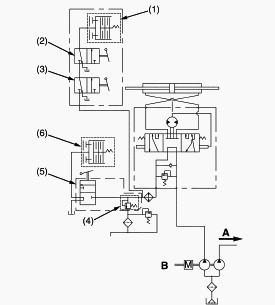
1 - Bi-Speed Turn Clutch, 2 - Bi-Speed Turn Valve 2, 3 - Bi-Speed Turn
Valve 1, 4 - Regulating Valve, 5 - Independent PTO Valve, 6 -
Independent PTO Clutch, A - To 3-Points Hitch, B - HST
Manual Transmission
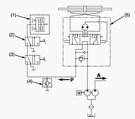
1 - Bi-Speed Turn Clutch, 2 - Bi-Speed Turn Valve 2, 3 - Bi-Speed Turn
Valve 1, 4 - Regulating Valve, 5 - Power Steering Controller, A - To
3-Points Hitch, P - From Pump Port
Kubota B3150, B3200, B3350 Transmission - Oil
Flow And Valves
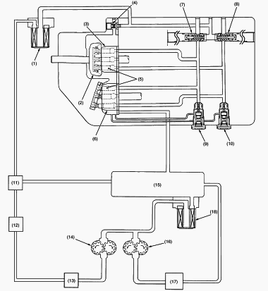
1 - Oil Filter Cartridge (for HST), 2 - Swashplate, 3 - Cylinder Block
(for Pump), 4 - Charge Relief Valve, 5 - Piston, 6 - Cylinder Block (for
Motor), 7 - Check and High Pressure Relief Valve (for Forward), 8 -
Check and High Pressure Relief Valve (for Reverse), 9 - Neutral Valve
(for Forward), 10 - Neutral Valve (for Reverse), 11 - Independent PTO
Control Valve, 12 - Oil Cooler, 13 - Power Steering, 14 - Hydraulic Pump
(for Power Steering, Independent PTO, HST), 15 - Oil Tank, 16 -
Hydraulic Pump (for 3-points Hitch), 17 - Hydraulic Control Valve (for
3-points Hitch), 18 - Oil Filter Cartridge
The pump and the motor are joined in a closed hydraulic circuit. Most of
oil circulates with in the main oil circuit. A little oil lubricates and
oozes out from the clearance between the moving parts in the case. Then
oil in the main oil circuit of the HST needs to be supplied a want. So
all of oil fed from hydraulic pump flow to hydraulic transmission for
charging and cooling. The charge oil aids smooth operation of pistons
for pump and motor. The charge oil passed to charge relief valve port.
The rest of oil passed through the charge relief valve into the HST
housing. And overflow oil from HST housing return to the transmission
case.
Neutral
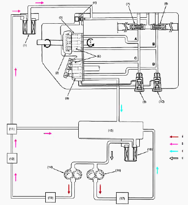
1 - Oil Filter Cartridge (for HST), 2 -
Swashplate, 3 - Cylinder Block (for Pump), 4 - Charge Relief Valve, 5 -
Piston, 6 - Cylinder Block (for Motor), 7 - Check and High Pressure
Relief Valve (for Forward), 8 - Check and High Pressure Relief Valve
(for Reverse), 9 - Neutral Valve (for Forward), 10 - Neutral Valve (for
Reverse), 11 - Independent PTO Control Valve, 12 - Oil Cooler, 13 -
Power Steering, 14 - Hydraulic Pump (for Power Steering, Independent
PTO, HST), 15 - Oil Tank, 16 - Hydraulic Pump (for 3-points Hitch), 17 -
Hydraulic Control Valve (for 3-points Hitch), 18 - Oil Filter Cartridge,
A - Pump A Port, B - Pump B Port, C - Motor C Port, D - Motor D Port, a
- High Pressure Oil, b - Low Pressure Oil, c - Free Oil, d - Suction Oil
When the speed control pedal (HST pedal) is in "Neutral", the variable
swashplate is right-angles to the pump pistons. And the pump pistons
only rotate with cylinder block (pump) without reciprocating. Since the
oil is not being pumped to the motor, the cylinder block (motor) is
stationary. And the output shaft does not rotate.
Forward
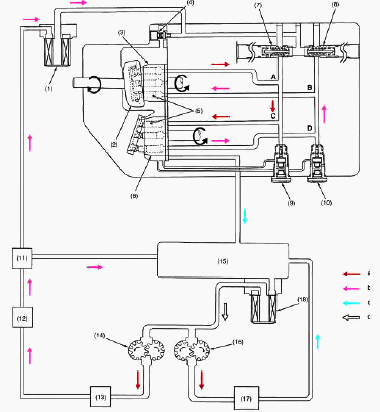
1 - Oil Filter Cartridge (for HST), 2 -
Swashplate, 3 - Cylinder Block (for Pump), 4 - Charge Relief Valve, 5 -
Piston, 6 - Cylinder Block (for Motor), 7 - Check and High Pressure
Relief Valve (for Forward), 8 - Check and High Pressure Relief Valve
(for Reverse), 9 - Neutral Valve (for Forward), 10 - Neutral Valve (for
Reverse), 11 - Independent PTO Control Valve, 12 - Oil Cooler, 13 -
Power Steering, 14 - Hydraulic Pump (for Power Steering, Independent
PTO, HST), 15 - Oil Tank, 16 - Hydraulic Pump (for 3-points Hitch), 17 -
Hydraulic Control Valve (for 3-points Hitch), 18 - Oil Filter Cartridge,
A - Pump A Port, B - Pump B Port, C - Motor C Port, D - Motor D Port, a
- High Pressure Oil, b - Low Pressure Oil, c - Free Oil, d - Suction Oil
When the speed control pedal (HST pedal) is stepped on and set to
"Forward", the variable swashplate is tilted as shown in figure above.
As the pump cylinder block rotates with the input shaft, oil is forced
out of pump port A at high pressure. As pressure oil from the pump
cylinder block enters to motor port C, the pistons, which align with
port C, are pushed against the swashplate and slide down the inclined
surface. Then the output shaft rotates with the motor cylinder block.
This drives the machine forward and the angle of pump swashplate
determines the output speed. As the motor cylinder block continues to
rotate, oil is forced out of motor port D at low pressure and retunes to
the pump port B.
Reverse
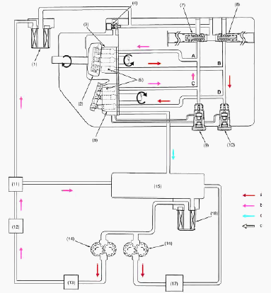
1 - Oil Filter Cartridge (for Hydrostatic
Transmission), 2 - Swashplate, 3 - Cylinder Block (for Pump), 4 - Charge
Relief Valve, 5 - Piston, 6 - Cylinder Block (for Motor), 7 - Check and
High Pressure Relief Valve (for Forward), 8 - Check and High Pressure
Relief Valve (for Reverse), 9 - Neutral Valve (for Forward), 10 -
Neutral Valve (for Reverse), 11 - Independent PTO Control Valve, 12 -
Oil Cooler, 13 - Power Steering, 14 - Hydraulic Pump (for Power
Steering, Independent PTO, HST), 15 - Oil Tank, 16 - Hydraulic Pump (for
3-points Hitch), 17 - Hydraulic Control Valve (for 3-points Hitch), 18 -
Oil Filter Cartridge, A - Pump A Port, B - Pump B Port, C - Motor C
Port, D - Motor D Port, a - High Pressure Oil, b - Low Pressure Oil, c -
Free Oil, d - Suction Oil
When the speed control pedal (HST pedal) is stepped on and set to
"Reverse", the variable swashplate is tilted as shown in figure above.
As the pump cylinder block rotates with the input shaft, oil is forced
out of pump port B at high pressure. As pressure oil from the pump
cylinder block enters to motor port D, the pistons, which align with
port D, are pushed against the swashplate and slide down the inclined
surface. Then the output shaft rotates with the motor cylinder block.
This drives the machine reward and the angle of pump swashplate
determines the output speed. As the motor cylinder block continues to
rotate, oil is forced out of motor port C at low pressure and retunes to
the pump port A.
Kubota B3150, B3200, B3350 Tractor -
Transmission Linkage
Cruise Control Linkage (Tractors with Cab)
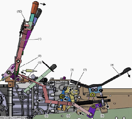
1 - Cruise Control Lever, 2 - Cruise Link Lever, 3 - Cruise Rear Rod, 4
- Cruise Front Rod, 5 - Neutral Holder, 6 - HST Plate, 7 - Trunnion
Shaft, 8 - HST Lever, 9 - HST Pedal, 10 - Release Lever
Cruise control system mainly consists of cruise control lever holding
section and cruise control releasing section. When the cruise control
lever (1) is set to the desired position, the bottom end of the cruise
link lever (2) turns clockwise. The control lever (1) pulls the cruise
rear rod (3). The cruise rear rod (3) pulls the cruise front rod (4).
The cruise front rod (4) pulls the neutral holder (5). The HST plate (6)
is pulled by the cruise front rod (4). Since the neutral holder (5)
turns clockwise, the trunnion shaft (7) directly attached to the neutral
holder (5) turns clockwise. On the other hand, since the HST plate (6)
pulls the HST lever (8) and the HST pedal (9). The HST pedal (9) is
turned to the front side. On the other hand, since release lever (10)
engage with tooth of lever guide RH, the cruise control lever (1) is
held at the desired cruise position until the brake pedals will be
depressed by an operator.
Cruise Control Release
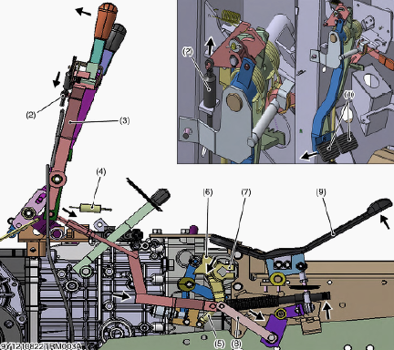
1 - Brake Pedal, 2 - Cruise Cable, 3 - Cruise Control Lever, 4 - Return
Spring, 5 - Return Spring, 6 - Neutral Holder, 7 - Trunnion Shaft, 8 -
HST Plate, 9 - HST Pedal
Cruise control release is done by depressing the brake pedals (1). When
an operator depresses the brake pedal (1), the cruise cable (2) is
pulled by the brake pedals (1). At the time, the cruise control lever
(3) is free. The cruise control lever (3) is returned to "NEUTRAL"
position by the return spring (4). On the other hand, the return spring
(5) pulls the neutral holder (6). The neutral holder (6) and the
trunnion shaft (7) turns counterclockwise. Since the neutral holder (6)
is connected to the HST plate (8), the HST plate (8) is pushed to the
front side. The HST plate (8) pushes the HST pedal (9) to return to
"NEUTRAL" position.
Cruise Control Linkage (ROPS Models)
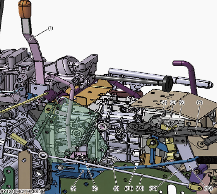
1 - Cruise Control Lever, 2 - Cruise Lock 1, 3 - Release Wire, 4 -
Roller, 5 - Neutral Holder, 6 - Trunnion Shaft, 7 - HST Pedal, 8 - Brake
Pedal, 9 - Cruise Lock 2, 10 - Brake Rod, 11 - Cruise Rod, 12 - HST
Plate, 13 - Hydrostatic Transmission Lever
When depressing the HST pedal (7) to "Forward", the HST lever (13), the
cruise rod (11) and the cruise lock 2 (9) moves forward. And when the
cruise control lever (1) is set to the desired position, the cruise lock
1 (2) is locked to the cruise lock 2 (9) and travelling speed is held to
the desired speed.
When depressing the brake pedals, the release wire (3), the cruise
control lever (1) and the cruise lock 1 (2) moves back. And the cruise
lock 1 (2) release from the cruise lock 2 (9). Cruise lock is changed
from "ON" to "OFF" position. Since the cruise lock is kept "OFF", the
neutral holder turns counterclockwise, and the roller is returned to
"Neutral" position. The HST pedal (7) also returns to "Neutral" position
and the tractor stops.
Kubota B3150, B3200, B3350 Tractor -
Independent PTO
Hydraulic Circuit
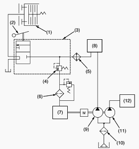
1 - PTO Clutch, 2 - Independent PTO Lever, 3 - Independent PTO Control
Valve, 4 - Relief Valve, 5 - Oil Cooler, 6 - Oil Filter Cartridge (for
HST), 7 - HST, 8 - Power Steering, 9 - Hydraulic Pump (for HST, Power
Steering and Independent PTO), 10 - Oil Filter Cartridge, 11 - Hydraulic
Pump (3-Points Hitch), 12 - 3-Points Hitch
Independent PTO Control Valve
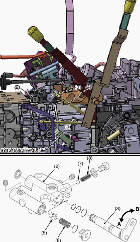
1 - Transmission Case, 2 - Independent PTO Control Valve, 3 - PTO Arm, 4
- Control Rod, 5 - Poppet, 6 - Spring, 7 - Ball, 8 - Spring, A - PTO arm
"OFF" position, B - PTO arm "ON" position
Independent PTO control valve (2) is located at transmission case (1).
The independent PTO control valve (2) consists of PTO arm (3), poppet
(5), ball (7) and etc. The PTO arm (3) is connected to control rod (4)
and the independent PTO lever. The PTO arm (3) is moved to "OFF" or "ON"
position by the independent PTO lever. Oil passage in the PTO arm (3) is
turned by the independent PTO lever. When the PTO arm (3) is moved to
"OFF" position, oil in the independent PTO control valve does not flow
to the oil passage. When the PTO arm (3) is moved to "ON" position, oil
in the independent PTO control valve flow to the oil passage. Poppet (5)
and spring (6) operate as a relief valve.
Independent PTO Lever Engaged
When the independent PTO lever is shifted to the "ENGAGED" position, the
PTO arm (3) is turned to "ON" position. Hydraulic oil from P port flows
through oil passage (7) of the PTO arm (3), oil passage S1 in the
transmission case (6) and oil passage S2 in the PTO clutch shaft (5) to
the PTO clutch (4). Since the piston of the PTO clutch (4) is pushed by
pressurized oil, clutch discs and clutch plates are pushed, and the PTO
clutch (4) is engaged.
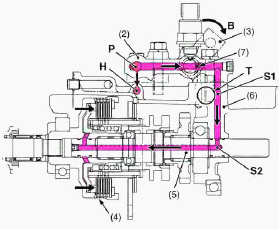
2 - Independent PTO Control Valve, 3 - PTO Arm, 4 - PTO Clutch, 5 - PTO
Clutch Shaft, 6 - Transmission Case, 7 - Oil Passage (in the PTO Arm), P
- Pump Port, H - HST Port, T - Tank Port, S1 - Oil Passage (in the
Transmission Case), S2 - Oil Passage (in the PTO Clutch Shaft)
Independent PTO Lever Disengaged
When the independent PTO lever is shifted to the "DISENGAGED" position,
the PTO arm (3) is turned to "OFF" position. Hydraulic oil is stopped at
the PTO arm (3). This oil flows to the HST port. Oil in the PTO clutch
(4) and the PTO clutch shaft (5) drains through oil passage S2, S1 and T
port to the transmission case.
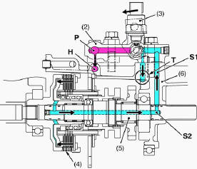
2 - Independent PTO Control Valve, 3 - PTO Arm, 4 - PTO Clutch, 5 - PTO
Clutch Shaft, 6 - Transmission Case, P - Pump Port, H - HST Port, T -
Tank Port, S1 - Oil Passage (in the Transmission Case), S2 - Oil Passage
(in the PTO Clutch Shaft)
Kubota B3150, B3200, B3350 Transmission -
Checking And Adjusting
Readjustment of Relief Valve (HST doesn't work due to its
loose hex. socket head screw)
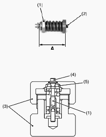
1 - Relief Valve Assembly, 2 - Hexagon Socket Head Screw, 3 - Relief
Valve Assembling Tool, 4 - Poppet, 5 - Valve Seat
Measure the pre-adjustment distance "A". Compress the spring of the
relief valve with a relief valve assembling tool (3). Then, find the
distance "A" by turning the poppet (4) with a screwdriver. The distance
"A" changes by about 0.5 mm (0.0197 in.) per one turn of the poppet (4).
Repeat the same operation a few times to find the distance "A" as it is
difficult to acquire at the first time. After finding the distance "A",
hold the setscrew (6) to a vice and fasten the hexagon socket head screw
(2) with specified torque. On this occasion, use a copper plate, etc.
for the vice jaws not to damage the setscrew (6). Install the relief
valve in the HST. Check the relief pressure. The distance "A" is for
refresh only. Make sure to check the relief pressure after readjustment.
The pressure changes by 1.47 MPa (213.3 psi) per 0.1 mm (0.0039 in.) in
distance "A". Relief valve readjusting pressure - 31.4 to 35.3 MPa (4551
to 5120 psi). Distance "A" - 37.9 to 38.0 mm (1.4921 to 1.4960 in).
Kubota B3150, B3200, B3350 - Hydrostatic
Transmission Service
Motor Shaft and Pump Shaft
Pull out the pump shaft from the HST housing case. Check the oil seal
surface the bearing surface and the bearing. If the shaft is rough or
grooved, replace it. If the bearing is worn, replace it. Motor Shaft -
Pull out the motor shaft from the HST housing case. Check the oil seal
surface the bearing surface and the bearing. If the shaft is rough or
grooved, replace it. If the bearing is worn, replace it.
Cylinder Block Bore and Pistons
Lift all the pistons gently with the retainer plate. Check the pistons
for their free movement in the cylinder block bores. If the piston or
the cylinder block bore is scored, replace cylinder block assembly. Do
not interchange pistons between pump and motor cylinder block. Pistons
and cylinder blocks are matched. Piston Slipper and Retainer Plate -
Check the slipper for flatness. If rounded, replace piston. Measure the
thickness of piston slipper. If the measurement is less than the
allowable limit, replace the piston. Check the lubricant hole for
clogging. Thickness of slipper - 3.00 mm (0.118 in).
Cylinder Block Face and Trunnion Shaft Cover
Check the polished face of cylinder block for scoring. If scored,
replace cylinder block assembly. Check the spring for breakage. If
broken, replace cylinder block assembly. Trunnion Shaft Cover - Check
the bearing for scratches and excessive wear. If worn or scored, replace
it. Check the oil seal and the O-rings for damage.
Valve Plate and Center Section Face
Check the engagement of the valve plate and the anchor pin. Pushing the
valve plate against the anchor pin, lift it to remove. Check the valve
plate for foreign particles. Clean the valve plate and dry with
compressed air. Check the valve plate for scratches, wear and erosion.
If worn or scored, replace it.
Thrust Plates and Bearing Surface
Check the thrust plate for scratches and excessive wear. If worn or
scored, replace it. Check the bearing surface of trunnion shaft
(swashplate) for scratches and excessive wear. If worn or scored,
replace it.
Center Section Oil Seals and Bearings
Check the oil seals for damage. Check the needle bearings for wear. If
the needle bearings and oil seals are worn, replace all seals and needle
bearings. After checking, coat the bearing with hydrostatic transmission
oil and the oil seal lip with grease.
Check and High Pressure Relief Valve
Check the valve plug and valve for scratches and damage. Check the valve
seat in the port block for damage. Check the spring for breakage and
wear. If anything unusual, replace the check and high pressure relief
valve assembly.
Neutral Valve and Charge Relief Valve
Check the holes of the valve body and the neutral valve for clogging. If
clogged, open hole with compressed air. Replace the O-rings and the
backup ring for scratches and damage. Check the springs for breakage and
wear. If the valve surface is scored, replace it. If anything is
unusual, replace it. Charge Relief Valve - Check the spring for breakage
and wear. If it is unusual, replace it.
Cylinder Block Bore and Pistons
Lift all the pistons gently with the retainer plate. Check the pistons
for their free movement in the cylinder block bores. If the piston or
the cylinder block bore is scored, replace cylinder block assembly.
Clearance between piston and bore - 0.02 mm (0.0008 in). Allowable limit
- 0.04 mm (0.0016 in).
Kubota B3150, B3200, B3350 - Independent PTO
Clutch Service
Bearing Check
Hold the inner race, and push and pull the outer race in all directions
to check for wear and roughness. Apply transmission fluid to the
bearing, and hold the inner race. Then, turn the outer race to check
rotation. If there is any defect, replace it.
Clutch Disc Wear
Measure the clutch disc thickness with vernier calipers. If the
thickness is less than the allowable limit, replace it. Clutch disc wear
- 1.70 to 1.90 mm (0.067 to 0.075 in). Allowable limit - 1.55 mm (0.061
in).
Steel Plate and Pressure Plate Wear
Measure the steel plate thickness with vernier calipers. Measure the
pressure plate thickness with vernier calipers. If the thickness is less
than the allowable limit, replace. Steel plate wear (without hole) -
0.95 to 1.05 mm (0.0374 to 0.0413 in). Allowable limit - 0.8 mm (0.031
in). Steel plate wear (with holes, with holes and rubber plugs) - 1.15
to 1.25 mm (0.045 to 0.049 in). Allowable limit - 1.10 mm (0.043 in).
Pressure plate wear - 1.95 to 2.05 mm (0.0768 to 0.0807 in). Allowable
limit - 1.8 mm (0.071 in).
Piston Return Spring Free Length and Tension
Measure the free length of the piston return spring with vernier
calipers. Place the piston return spring on a spring compression tester
and compress to the specified length, and read the gauge. If the
measurement is less than the allowable limit, replace. Piston / return
spring free length - 34.5 mm (1.36 in). Piston return spring tension -
614.2 N / 17.8 mm.
________________________________________________________________________________
________________________________________________________________________________________
________________________________________________________________________________________
| KUBOTA TRACTORS SPECIFICATIONS |
________________________________________________________________________________________
________________________________________________________________________________________
________________________________________________________________________________________
________________________________________________________________________________________
________________________________________________________________________________________
________________________________________________________________________________________
________________________________________________________________________________________
________________________________________________________________________________________
________________________________________________________________________________________
________________________________________________________________________________________
________________________________________________________________________________________
________________________________________________________________________________________
________________________________________________________________________________________
________________________________________________________________________________________
________________________________________________________________________________________
| KUBOTA ENGINES DATA AND SERVICE SPECS |
________________________________________________________________________________________
________________________________________________________________________________________
________________________________________________________________________________________
________________________________________________________________________________________
________________________________________________________________________________________
| KUBOTA FRONT END LOADERS |
________________________________________________________________________________________
________________________________________________________________________________________
________________________________________________________________________________________
________________________________________________________________________________________
________________________________________________________________________________________
________________________________________________________________________________________
________________________________________________________________________________________
________________________________________________________________________________________
________________________________________________________________________________________
________________________________________________________________________________________
________________________________________________________________________________________
________________________________________________________________________________________
| KUBOTA TRACTORS TROUBLESHOOTING | ||||
| L235 | L2501 | L2550 | L275 | L3110 |
| L3301 | L35 | L3710 | L3901 | L4310 |
| L5030 | M4700 | M5700 | M6040 | M6800 |
| M8200 | M8540 | M9000 | MX5100 | MX5200 |

 SPECIFICATIONS
 LOADERS
 ENGINES
 MAINTENANCE
 PROBLEMS
 B1241
B1241 B1600
B1600 B1700
B1700 B1750
B1750 B21 Backhoe
 B2150
B2150 B2301
B2301 B2320
B2320 B2530
B2530 B26 Backhoe
 B2601
B2601 B2650HSD
 B3030
B3030 B3350
B3350 B6000
B6000 B6100
B6100 B6200
B6200 B7000
B7000 B7001
B7001 B7100HST
 B7200
B7200 B7500
B7500 B7510
B7510 B7800
B7800 B8200HST
 BX1880
 BX2200
 BX2230
 BX2350
 BX2370
 BX23S
BX23S BX25 TLB
 BX2660
 BX2680
 F3680
F3680 L175
L175 L185
L185 L210
L210 L225
L225 L235
L235 L245
L245 L260
L260 L275
L275 L285
L285 L305
L305 GR2120
 L1501
L1501 L2350
L2350 L2550
L2550 L2800
L2800 L3010
L3010 L3200HST
 L3301
L3301 L3560
L3560 L3800
L3800 L4701
L4701 L5740
L5740 M5-091
 M5-111
 M6060
M6060 M7040
M7040 M9540
M9540 M9960
M9960 MX5100
 D662
D662 D722
D722 D750
D750 D782
D782 D850
D850 D902
D902 D905
D905 D950
D950 D1005
D1005 D1100
D1100 D1105
D1105 D1503
D1503 D1703
D1703 D1803
D1803 V1200
V1200 V1205
V1205 V1305
V1305 V1505
V1505 V2203
V2203 V2403
V2403 Z482
Z482 Z602
Z602 Z750
Z750 Z1100
Z1100 Z1300
Z1300 B1630
B1630 BF400
BF400 BF400G
 LA181
LA181 LA203
LA203 LA211
LA211 LA243
LA243 LA271
LA271 LA272
LA272 LA301
LA301 LA302
LA302 LA304
LA304 LA340
LA340 LA344
LA344 LA351
LA351 LA352
LA352 LA364
LA364 LA401
LA401 LA402
LA402 LA434
LA434 LA463
LA463 LA481
LA481 LA482
LA482 LA504
LA504 LA513
LA513 LA514
LA514 LA524
LA524 LA525
LA525 LA534
LA534 LA555
LA555 LA680
LA680 LA681
LA681 LA682
LA682 LA703
LA703 LA714
LA714 LA723
LA723 LA724
LA724 LA764
LA764 LA765
LA765 LA805
LA805 LA844
LA844 LA852
LA852 LA853
LA853 LA854
LA854 LA1002
 LA1055
 LA1065
 LA1153
 LA1154
 LA1251
 LA1301S
 LA1353
 LA1403
 LA1601S
 LA1854
 LA1944
 LA1953
 LA2253
 LM2605