________________________________________________________________________________
Kubota B5100, B5200 - Mechanical Transmission
Kubota B5100, B5200 Tractor - Six-Speed
Transmission

1.Knob, 2.Shift lever, 3.Cover, 4.Snap ring, 5.Spring, 6.Bushing,
7.Check plate bolt, 8.O-ring, 9.Gasket, 10.Rod guide pin, 11.Shift
cover, 12.Check plate, 13.Washer, 14.Castle nut, 15.Cotter key, 16.Pin,
17.Shift fork, 18.Ball, 19.Spring, 20.Cotter key, 21.Rail, 22.O-ring,
23.Tab washer, 24.Cap screw, 25.Rail, 26.Shift fork, 27.Ball, 28.Spring,
29.Lever, 30.O-ring, 31.Plate, 32.Grip, 33.Range shift lever, 34.Pin,
35.Rail, 36.Shift fork, 37.Ball, 38.Spring, 39.Cotter key, 40.Lever,
41.O-ring, 42.Plate, 43.Front-wheel drive select lever, 44.Grip, 45.Pin,
46.Plug, 47.Cover plate
Main shift lever (2) selects gear positions through an H-pattern. When
range shift lever (33) is placed in the low range position (up
position), reverse one and forward one, two and three are attainable.
When range shift lever (33) is placed in the high range position (down
position), reverse two and forward four, five and six are attainable.
Kubota B5100, B5200 - Clutch
housing/Transmission Case Split
Drain transmission/hydraulic system fluid into a suitable container.
Raise hood and disconnect battery cable from negative battery post.
Remove air cleaner assembly and right side cover. Disconnect throttle
linkage. Close fuel shut-off valve at fuel filter, then disconnect fuel
supply line from fuel pump. Remove line connecting fuel tank to fuel
filter at filter port and plug openings to prevent fuel spillage. Remove
fuel filter assembly. Detach hydraulic lines as needed. Remove bolts and
nuts connecting step plates to fenders.
Detach brake pedal rod and differential lock rod
from under step plate. If so equipped, disconnect flasher lamp wiring at
rear fenders. Support rear of tractor. Attach a hoist with suitable
holding fixtures to clutch housing. Remove nuts securing clutch housing
to transmission case, then separate components. Reassembly is reverse
order of splitting procedure. Tighten nuts securing clutch housing to
transmission case to 61-107 Nm (45-79 ft-lbs.) torque. Capacity of
transmission/hydraulic system is 8.5 liters (2.21 gal.) or 11.5 liters
(3 gal.). Refill with the following transmission/hydraulic fluid or a
suitable equivalent.
Kubota B5100, B5200 Transmission - Remove And
Reinstall
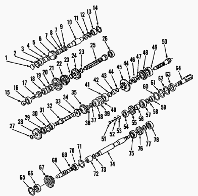
1. Cap, 2. Snap ring, 3. Bearing, 4. Bushing, 5. Thrust washer, 6. Gear,
7. Needle bearings, 8. Spacer, 9. Thrust washer, 10. Reverse shaft, 11.
Shim, 12. Thrust washer, 13. Needle bearing, 14. Snap ring, 15. Oil
seal, 16. Bearing, 17. Input shaft, 18. Bearing, 19. Spacer, 20.
Bearing, 21. Gear, 22. Gear, 23. Snap ring, 24. Gear, 25. Fourth shaft,
26. Bearing, 27. Snap ring, 28. Gear, 29. Bearing, 30. Snap ring, 31.
Bearing, 32. Second shaft, 33. Spacer, 34. Gear, 35. Gear, 36. Shim, 37.
Thrust washer, 38. Bearing, 39. Shim, 40. Spacer, 41. Bearing, 42.
Bushing, 43. Spacer, 44. Snap ring, 45. Gear, 46. Spacer, 47. Stop
collar, 48. Bearing, 49. Bearing, 50. Bevel pinion gear, 51. Cap screw,
52. Washer, 53. Washer, 54. Bearing, 55. PTO-gear, 56. Spacer, 57.
Bearing, 58. Spacer, 59. Bushing, 60. Shim, 61. Shim, 62. Spacer, 63.
Oil seal, 64. Pto shaft, 65. Snap ring, 66. Bearing, 67. Gear, 68. Third
shaft, 69. Thrust washer, 70. Bearing, 71. Snap ring, 72. Coupling, 73.
Snap ring, 74. PTO drive shaft, 75. Bearing, 76. Gear, 77. Snap ring,
78. Bearing
Split clutch housing from transmission case. Remove shift cover (11) as
an assembly with shift components. Remove hydraulic lift covers. Remove
cap screws and nuts securing gear transmission case to center housing.
Separate assemblies, then withdraw transmission assembly while being
careful not to allow any component to fall free. Installation is reverse
order of removal. Tighten cap screws and nuts securing transmission to
center housing to 39-43 Nm (29-32 ft-lbs.) torque. Install shift cover
assembly.
Kubota B5100, B5200 Tractor - Differential
lock
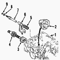
1.Center housing, 2.Differential case, 3.Differential lock cam, 4.Bull
pinion gear, 5.Spring, 6.Fork, 7.Engagement rod, 8.Shim, 9.O-ring
Differential lock assembly mounts in right axle case housing. To service
differential lock components, remove right axle case assembly. Separate
differential lock components. Inspect all components for excessive wear
and damage. Make sure engagement teeth on cam (3) and differential case
(2) engage properly and are not chipped, cracked or damaged in any other
way. Measure free length of differential lock spring (5), reference
value is 40 mm (1.5748 inches). Renew all parts as needed. Reassembly is
reverse order of disassembly. Reinstall right axle case assembly. Adjust
differential lock pedal travel to a length of 28 mm (1.1024 inches).
Kubota B5100, B5200 - Power Take-Off
Two rear PTO speeds are available on Models B5100 and B5200. Power
take-off second and third speed ranges should never be used except when
following the implement instructions. When PTO select lever is placed in
first speed range, rear PTO shaft will rotate at a speed of 603 rpm when
engine speed is set at 3000 rpm. When Power take-off select lever is
placed in second speed range, rear PTO shaft will rotate at a speed of
963 rpm when engine speed is set at 3000 rpm.
Rear PTO
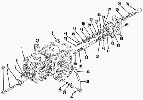
1.Transmission case, 2.Center housing, 3.Shift rail, 4.Shift fork,
5.Ball, 6.Spring, 7.Rod, 8.Thrust washer, 9.Needle bearings, 10.Gear,
11.Thrust washer, 12.Gasket, 13.Lock screw, 14.Tab washer, 15.Shaft,
16.Cap, 17.Oil seal, 18.Cover plate, 19.Gasket, 20.Bearing, 21.Shaft and
gear, 22.Bearing, 23.Mid-PTO case, 24.Gasket, 25.Drain plug, 26.Dowel
pin, 27.Lever, 28.O-ring, 29.Plate, 30.Select plate, 31.Select lever,
32.Pin, 33.Grip, 34.One-way clutch, 35.Snap ring, 36.Spring, 37.Bushing,
38.PTO drive shaft, 39.Bearing, 40.PTO drive gear, 41.Snap ring,
42.Bearing, 43.Cap screw, 44.Washer, 45.Washer, 46.Washer, 47.Bearing,
48.PTO gear, 49.Spacer, 50.Bearing, 51.Spacer, 52.Bushing, 53.Shim,
54.Rear cover, 55.Seal, 56.PTO output shaft, 57.Cap, 58.Shim, 59.Spacer,
60.Coupler, 61.Gasket, 62.Collar, 63.Spacer
To remove power take-off components located in center housing, first
remove the six cap screws securing rear cover (54) to center housing
(2). Using a suitable mallet, lightly tap rear cover (54) to separate
components, then withdraw rear cover assembly. Using a suitable puller,
extract bearing (42) from shaft end (38). Remove snap ring (41), then
withdraw gear (40). To remove shaft (38), remove hydraulic lift cover.
Using a suitable mallet, lightly tap shaft rearward to break bearing
(39) loose from center housing bore, then extract shaft. Note coupler
(60). Remove all components as needed that will obstruct in center
housing and transmission case split.
Using suitable holding fixtures, support center
housing and transmission case, then split units apart. Remove snap ring
(35) and withdraw one-way clutch half (34) and spring (36). Lightly tap
front end of shaft (38) to dislodge bearing (39) from center housing
bore, then extract shaft. Inspect components and renew any which are
damaged or excessively worn. Installation is reverse of removal. Tighten
cap screws securing center housing to transmission case to 19-32 Nm
(14-24 ft-lbs.) torque and nuts to 25-39 Nm (18-29 ft-lbs.) torque.
Kubota B5100, B5200 - Rear Axle Differential
and Bevel Gears
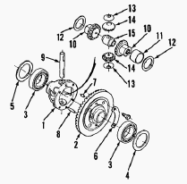
1.Differential case, 2.Bevel ring gear, 3.Bearing, 4.Shim (left), 5.Shim
(right), 6.Lock plate, 7.Knock pin, 8.Retaining pin, 9.Cross-shaft,
10.Side gear, 11.Bushing, 12.Thrust washer, 13.Thrust washer, 14.Spider
gear, 15.Thrust collar
Disconnect and remove differential lock and brake rods. Remove control
rod from control valve actuating lever. Remove three cap screws
retaining control valve to lift cover, then separate components being
careful not to drop the two O-rings. Remove bracket mounted to lift
cover cylinder head. Remove top link bracket at rear of lift cover.
Remove the nine cap screws securing lift cover to center housing, then
tap lift cover upwards using a suitable mallet. Note that lift cover
must be lifted upward because of dowel pins located in center housing.
Remove the ten cap screws retaining left and right axle case assemblies
to center housing. Tap axle shaft with a suitable mallet to break
components apart, then carefully extract assemblies. Remove left and
right differential bearing holders and withdraw shims (4 and 5). Lift
out differential and bevel ring gear assembly from center housing.
Installation is reverse order of removal. Renew all gaskets and O-rings.
Backlash between bevel ring gear and bevel pinion should be 0.1-0.2 mm
(0.004-0.008 inch) with an allowable limit of 0.4 mm (0.016 inch).
Adjust by varying thickness of shim (4 or 5) until recommended backlash
is attained. Tighten cap screws securing left and right axle case to
center housing to 48-56 Nm (35-41 ft-lbs.) torque for M10 cap screws and
77-90 Nm (57-67 ft-lbs.) torque for M12 cap screws. Tighten cap screws
securing lift cover to center housing to 25-29 Nm (19-22 ft-lbs.)
torque. Tighten cap screws mounting top link bracket to lift cover to
41-47 Nm (30-35 ft-lbs.) torque. Adjust differential lock control rod.
Adjust brake pedal free play.
________________________________________________________________________________
________________________________________________________________________________________
________________________________________________________________________________________
| KUBOTA TRACTORS SPECIFICATIONS |
________________________________________________________________________________________
________________________________________________________________________________________
________________________________________________________________________________________
________________________________________________________________________________________
________________________________________________________________________________________
________________________________________________________________________________________
________________________________________________________________________________________
________________________________________________________________________________________
________________________________________________________________________________________
________________________________________________________________________________________
________________________________________________________________________________________
________________________________________________________________________________________
________________________________________________________________________________________
________________________________________________________________________________________
________________________________________________________________________________________
| KUBOTA ENGINES DATA AND SERVICE SPECS |
________________________________________________________________________________________
________________________________________________________________________________________
________________________________________________________________________________________
________________________________________________________________________________________
________________________________________________________________________________________
| KUBOTA FRONT END LOADERS |
________________________________________________________________________________________
________________________________________________________________________________________
________________________________________________________________________________________
________________________________________________________________________________________
________________________________________________________________________________________
________________________________________________________________________________________
________________________________________________________________________________________
________________________________________________________________________________________
________________________________________________________________________________________
________________________________________________________________________________________
________________________________________________________________________________________
________________________________________________________________________________________
| KUBOTA TRACTORS TROUBLESHOOTING | ||||
| L235 | L2501 | L2550 | L275 | L3110 |
| L3301 | L35 | L3710 | L3901 | L4310 |
| L5030 | M4700 | M5700 | M6040 | M6800 |
| M8200 | M8540 | M9000 | MX5100 | MX5200 |

 SPECIFICATIONS
 LOADERS
 ENGINES
 MAINTENANCE
 PROBLEMS
 B1241
B1241 B1600
B1600 B1700
B1700 B1750
B1750 B21 Backhoe
 B2150
B2150 B2301
B2301 B2320
B2320 B2530
B2530 B26 Backhoe
 B2601
B2601 B2650HSD
 B3030
B3030 B3350
B3350 B6000
B6000 B6100
B6100 B6200
B6200 B7000
B7000 B7001
B7001 B7100HST
 B7200
B7200 B7500
B7500 B7510
B7510 B7800
B7800 B8200HST
 BX1880
 BX2200
 BX2230
 BX2350
 BX2370
 BX23S
BX23S BX25 TLB
 BX2660
 BX2680
 F3680
F3680 L175
L175 L185
L185 L210
L210 L225
L225 L235
L235 L245
L245 L260
L260 L275
L275 L285
L285 L305
L305 GR2120
 L1501
L1501 L2350
L2350 L2550
L2550 L2800
L2800 L3010
L3010 L3200HST
 L3301
L3301 L3560
L3560 L3800
L3800 L4701
L4701 L5740
L5740 M5-091
 M5-111
 M6060
M6060 M7040
M7040 M9540
M9540 M9960
M9960 MX5100
 D662
D662 D722
D722 D750
D750 D782
D782 D850
D850 D902
D902 D905
D905 D950
D950 D1005
D1005 D1100
D1100 D1105
D1105 D1503
D1503 D1703
D1703 D1803
D1803 V1200
V1200 V1205
V1205 V1305
V1305 V1505
V1505 V2203
V2203 V2403
V2403 Z482
Z482 Z602
Z602 Z750
Z750 Z1100
Z1100 Z1300
Z1300 B1630
B1630 BF400
BF400 BF400G
 LA181
LA181 LA203
LA203 LA211
LA211 LA243
LA243 LA271
LA271 LA272
LA272 LA301
LA301 LA302
LA302 LA304
LA304 LA340
LA340 LA344
LA344 LA351
LA351 LA352
LA352 LA364
LA364 LA401
LA401 LA402
LA402 LA434
LA434 LA463
LA463 LA481
LA481 LA482
LA482 LA504
LA504 LA513
LA513 LA514
LA514 LA524
LA524 LA525
LA525 LA534
LA534 LA555
LA555 LA680
LA680 LA681
LA681 LA682
LA682 LA703
LA703 LA714
LA714 LA723
LA723 LA724
LA724 LA764
LA764 LA765
LA765 LA805
LA805 LA844
LA844 LA852
LA852 LA853
LA853 LA854
LA854 LA1002
 LA1055
 LA1065
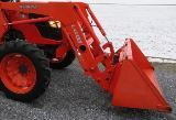 LA1153
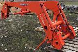 LA1154
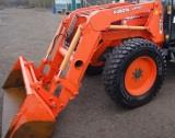 LA1251
 LA1301S
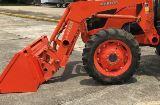 LA1353
 LA1403
 LA1601S
 LA1854
 LA1944
 LA1953
 LA2253
 LM2605