________________________________________________________________________________
Kubota B6200, B7200 - Hydrostatic Transmission
Kubota B6200HST, B7200HST Tractor -
Transmission System
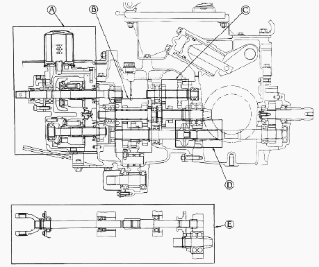
A - Hydrostatic transmission, B - PTO shift section (1-2-N), C -
High-low gear shift section, D - One-way clutch cam section, E - Front
wheel drive section (Engaged - Disengaged)
The transmission consists of HST (Hydrostatic Transmission) and a series
of gears shown in pic. It offers the most suitable speeds for traveling
and operation by combination of them. And power is transmitted to the
front or rear axles and the PTO shafts, which are classified
respectively as the traveling system and PTO system. The traveling
system consists of the HST (A), high-low gear shift section (C) and
front wheel drive section (E). The traveling speeds are selected by the
operation of the speed control pedal and the high-low gear shift lever.
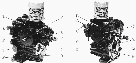
1 - Charge Relief Valve, 2 - Neutral Valve, 3 - Trunnion Shaft W Port
Block, 5 - High Pressure Relief Valve, 6 - Variable Displacement Piston
Pump, 7 - Charge Pump, 8 - Input Shaft, 9 - Case, 10 - Fixed
Displacement Piston Motor, 11 - Output Shaft

1-Oil Filter Cartridge, 2-Joint, 3-Thrust Plate, 4-P3 Port, 5-Trocoid
Rotor Assembly, 6-Charge Pump Case, 7-Input Shaft, 8-Oil Seal, 9-Ball
Bearing, 10-Case, 11-Ball Bearing, 12-Fixed Swashplate, 13-Piston,
14-Cylinder Block, 15-Drain Plug, 16-Valve Plate, 17-Variable
Swashplate, 18-Piston, 19-Cylinder Block, 20-Port Block, 21-Valve Plate,
22-Variable Displacement Piston Pump, 23-Oil Seal, 24-Case Relief Valve,
25-Fixed Displacement Piston Motor, 26-Oil Seal, 27-Output Shaft
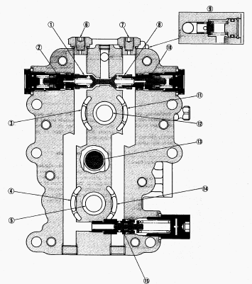
1-Check Valve, 2-Neutral Valve (Forward), 3-Pump Kidney Port A, 4-Motor
Kidney Port C, 5-Output Shaft, 6-P1 Port, 7-P2 Port, 8-Check Valve,
9-Charge Relief Valve, 10-Neutral Valve (Reverse), 11-Pump Kidney Port
В, 12-Input Shaft, 13-Case Relief Valve, 14-Motor Kidney Port D, 15-High
Pressure Relief Valve
Variable Swashplate
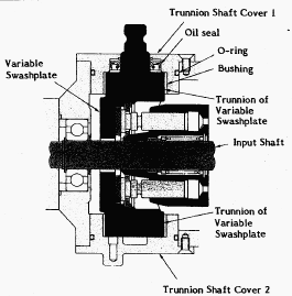
This pump is variable displacement one. The angle of its swashplate can
be varied so that the volume and pressure of oil pumped by the pistons
can be changed or the direction of oil flow can be reversed. The
swashplate is moved around the trunnion shaft with the neutral holder,
by stepping on the speed control pedal linked to the neutral holder.
Kubota B6200, B7200 Transmission - Oil Flow
and Valves
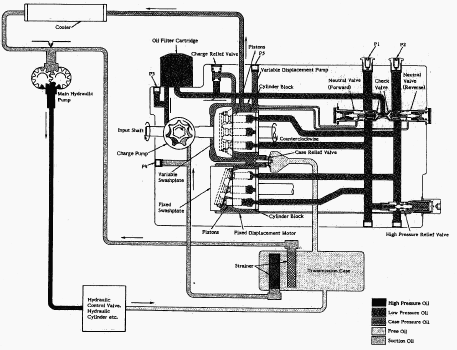
P1. Port for checking high pressure (forward), P2. Port for checking
high pressure (reverse), P3. Port for checking case pressure, P4. Port
for checking vacuum, P5. Port for checking case pressure
The pump and motor are joined in a closed hydraulic loop and most of oil
circulates within the main oil circuit. A little oil lubricates and
oozes out from the clearance between the moving parts to the case. Then
oil in the main oil circuit of the hydrostatic transmission needs to be
supplied a want. So all of oil fed from the main hydraulic pump flows to
the hydrostatic transmission for charging. Only return oil from the
hydraulic cylinder drops to the transmission case. The charge oil aids
smooth operation of piston pump and motor. The rest of the oil passes
through the charge relief valve into the case. Then the oil passes to
the main hydraulic pump through a cooler.
Neutral Valve
The neutral valves in the main oil circuit lines are open and pass the
oil to the case when in neutral, and the oil pressure in their lines
becomes low. And when the oil pressure in the high pressure line
increases to a specified pressure, the neutral valve closes. Valve
operating pressure - 3.24 MPa (469 psi).
High Pressure Relief Valve
The high pressure relief valve between the two lines in the main oil
circuit monitors the oil pressure in each line. When excessively high
pressure is built up in one line, it opens and flows the oil into
another line. Valve operating pressure - 22.5 to 24.5 MPa (3270 to 3560
psi).
Case Relief Valve
The case relief valve monitors the oil pressure in the hydrostatic
transmission case. When the oil pressure rises, it opens and flows the
oil directly to the transmission case, so that the oil may not leak
against the sealings. Valve operating pressure - 170 to 230 kPa (24 to
32 psi).
Kubota B6200, B7200 Transmission - Control
Linkage
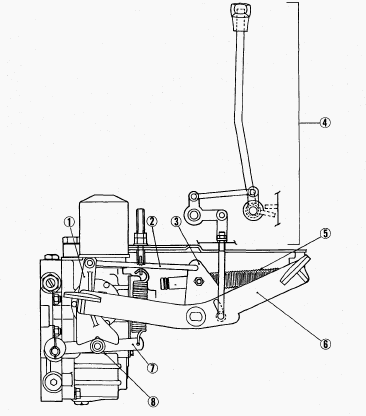
1-Neutral Holder, 2-Speed Control Rod, 3-Rod Guide, 4-Speed Set Device,
5-Damper, 6-Speed Control Pedal, 7-Neutral Holder Arm, 8-Roller
The speed control pedal (6) and the trunnion shaft of variable
swashplate are linked with the rod guide (3), the speed control rod (2)
and the neutral holder (1). As the front footrest of the pedal is
depressed, the swashplate rotates and forward traveling speed increases.
Depressing the rear footrest increases reverse speed. The roller (8) on
the neutral holder arm (7) hanged with spring seats the detent of the
neutral holder (1) so that the neutral holder returns to neutral. Then,
the swashplate is returned to neutral with the neutral holder, when the
pedal is released. The damper (5) connected to the rod guide (3)
restricts the movement of the linkage to prevent abrupt operation or
reversing. The speed set device (4) linked to the rod guide (3) enables
the linkage not to return to neutral and to keep a certain forward speed
while the speed control pedal (6) is released. On B6200, this device is
installed as optional.
Kubota B6200HST, B7200HST Tractor - Mechanical
Transmission
High-Low Gear Shift Section
Mechanical transmission receives engine power from the output shaft of
hydrostatic transmission and selects high or low gear, and transmits the
power to differential.
Neutral
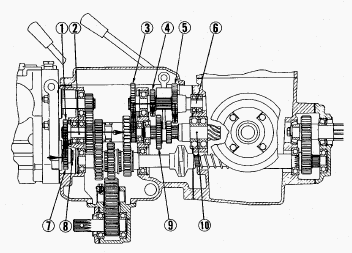
1 - 14T Gear, 2 - 2nd Shaft, 3 - 24T Gear, 4 - 15T Gear, 5 - 23T Gear, 6
- 4th Shaft, 7 - 16T Gear, 8 - Output Shaft, 9 - 20T-12T Gear, 10 -
Spiral Bevel Pinion
High or low speed is obtained by shifting 20T-12T gear (9) splined to
spiral bevel pinion (10). When in neutral, neither 15T gear (4) nor 23T
gear (5) meshes with 20T-12T gear (9) on spiral bevel pinion (10).
Engine power is transmitted to the output shaft (8) of hydrostatic
transmission, to which 16T gear (7) is splined. 16T gear (7) and 14T
gear (1) are in mesh. 14T gear (1) is splined to 2nd shaft (2). Integral
11T gear on 2nd shaft (2) and 24T gear (3) are in mesh. 24T gear (3) is
splined to 4th shaft (6). To 4th shaft (6), 15T gear (4) and 23T gear
(5) are also splined. Spiral bevel pinion (10) is not driven.
Low
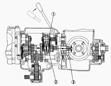
1 - 15T Gear, 2 - 20T-12T Gear, 3 - Spiral Bevel Pinion
20T-12T gear (2) is shifted and 20T gear meshes with 15T gear (1)
splined to spiral bevel pinion (3). Then power is transmitted to
differential.
High
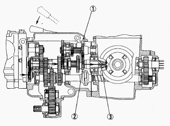
1 - 23T Gear, 2 - 20T-12T Gear, 3 - Spiral Bevel Pinion
20T-12T gear (2) is shifted and 12T gear meshes with 23T gear (1)
splined to spiral bevel pinion (3). Then power is transmitted to
differential.
Front Wheel Drive Section (4WD-Type)
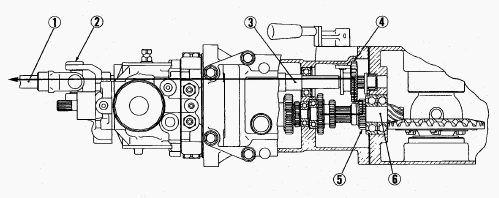
1 - Drive Shaft, 2 - Universal Joint, 3 - Front Wheel Drive Shaft, 4 -
24T Gear, 5 - 16T Gear, 6 - Spiral Bevel Pinion
The front wheel drive is used when greater traction power is required or
to prevent the tractor from being pushed during rotary tilling of hard
soil. 2-wheel drive or 4-wheel drive is selected by changing position of
24T gear (4) on the front wheel drive shaft (3) with the front drive
lever. When the front drive lever is set to "Disengaged", 24T gear is in
neutral and power is not transmitted to the front drive shaft. When the
front drive lever is set to "Engaged", 24T gear slides rearward to
engage with 16T gear (5) on the spiral bevel pinion shaft (6).
Therefore, the front drive shaft is actuated to drive the front wheels.
Kubota B6200, B7200 - PTO Shift Section
PTO system is independent of HST. Engine revolution is directly
transmitted to the 2nd shaft (4).
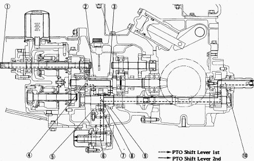
1 - Input Shaft of HST, 2 - 14T Gear, 3 - 18T Gear, 4 - 2nd Shaft, 5 -
21T Gear, 6 - Mid PTO Shaft, 7 - 21T Gear, 8 - 3rd Shaft, 9 - 17T Gear,
10 - Rear PTO Shaft
Neutral - The 14T gear (2) meshes with the 21T gear (5)
on the 3rd shaft (8). And the 18T gear (3) meshes with the 17T gear (9)
on the 3rd shaft (8), too. But the 21T gear (5) and the 17T gear (9)
unite with needle bearing in itself, they run idle on the 3rd shaft (8).
Then the 3rd shaft (8) is not driven.
1st Position - The 21T gear (7) splined to the 3rd
shaft (8) is shifted forward, and then the 3rd shaft (8) is rotated.
Rear PTO shaft (10) speed is 540 rpm at an engine speed of 2517 rpm. Mid
PTO shaft (6) speed is 1546 rpm at an engine speed of 2517 rpm.
2nd Position - The 21T gear (7) shifted to the 3rd
shaft (8) is shifted rearward, and then the 3rd shaft (8) is rotated.
Rear PTO shaft (10) speed is 858 rpm at an engine speed of 2517 rpm. Mid
PTO shaft (6) speed is 2456 rpm at an engine speed of 2517 rpm.
Kubota B6200, B7200 One-Way Clutch Cam Section
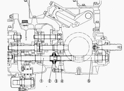
1 - 3rd Shaft, 2 - Clutch Cam, 3 - Clutch Cam, 4 - Cam Spring, 5 - 5th
Shaft
The one-way clutch cam is also called an overrunning clutch. It is
composed of a pair of clutch cams (2), (3) and a cam spring (4). One of
the clutch cams is splined to the 3rd shaft (1), and the other is
splined to the 5th shaft (5). These two clutch cams are engaged with
each other by the force of the cam spring. As long as the 3rd shaft is
rotating faster than the 5th shaft, these two clutch cams will remain
engaged, and the 5th shaft is driven.
Kubota B6200, B7200 - Transmission Service
Transmission Oil Change
Remove the drain plugs to drain transmission oil. Screw in the drain
plugs. Fill new oil up to the upper line on the dipstick
Transmission Oil Filter Cartridge Replacement
The oil filter cartridge must be replaced after initial 50 hours and
every 200 service hours. Remove the bolts which secure the cover. Remove
the oil filter cartridge by using the filter wrench. Lightly tighten the
screw by using a screwdriver. Apply a slight coat of oil onto the
cartridge gasket. To install the new cartridge, screw it in by hand.
Over tightening may cause deformation of rubber gasket. After the new
cartridge has been replaced, the transmission oil level will become a
little lower. Make sure that the transmission oil does not leak through
the seal. Check the oil level.
Kubota B6200, B7200 Hydrostatic Transmission (HST)
Remove the propeller shaft from the 1st shaft. Remove the drive shaft
from the front wheel drive shaft (4WD type only). Remove the HST
mounting screws, and remove the HST. After inserting the spring pin to
the 1st shaft and drive shaft, lock the spring pin with a wire. HST
mounting screw (Tightening torque) - 48 to 56 Nm (35.4 to 41.2 ft-lbs).
Control Valve and Top Link Bracket
Remove the control valve with the feedback rod (4WD type). Remove the
control valve with the check rod (2WD type). Remove the top link
bracket. Use care not to damage the О-rings on the control valve.
Control valve mounting screw (B6200HST, B7200HST 4WD type) - 16.7 to
21.6 Nm (12.3 to 15.9 ft-lbs). Control valve mounting screw (B6200HST,
B7200HST 2WD type) - 16.7 to 21.6 Nm (12.3 to 15.9 ft-lbs). Top link
bracket mounting screw - 39.2 to 64.7 Nm (28.9 to 47.7 ft-lbs).
Separating Transmission Case
Remove the bolt. Remove the fork shaft lock screw. Remove the
transmission case mounting nuts, and separate the transmission case.
Apply liquid gasket (Three Bond 1102 or equivalent) to both sides of new
gasket. Transmission case mounting nut (Tightening torque) - 39.2 to
64.7 N-m (28.9 to 47.7 ft-lbs).
Case and Case Relief Pressure Checking
Remove the 1/4 plug from port, with care not to allow any particle of
sealing tape enter into the port. Install the long connector to port
with sealing tape on its thread. Install the threaded joint to long
connector with the gasket between them. Install the cable, threaded
joint in relief valve set pressure tester and low pressure gauge to
threaded joint in order. Run the engine at 2600 to 2700 rpm. Place the
high-low shift lever in neutral. Release the speed control pedal to set
in neutral. After measuring the case pressure, remove the eye joint from
port and plug the port with 3/8 screw to measure the case relief
pressure.
Kubota B6200HST, B7200HST - Mid-PTO
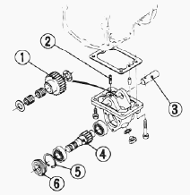
1 - 24T Gear, 2 - Screw, 3 - Shaft, 4 - 11T Gear Shaft, 5 - Cover, 6 -
Oil Seal
Separate the mid-PTO case from the transmission case. Remove the mid-PTO
case cover (5). Remove the screw (2) and pull out the mid-PTO counter
shaft (3) and remove the 24T gear (1). Draw out the 11T gear shaft (4)
with the bearing on it. After tapping the spring pin (2) into the shaft
(3), remove the shaft (3) and the 24T gear (1). Remove the oil seal (6)
and the external snap ring (5). Draw out the 11T gear shaft (4) with the
bearing on it. Mid-PTO case cover to case - 14 to 20 Nm (10 to 14
ft-lbs). Mid-PTO case to transmission case - 48 to 56 Nm (35 to 41
ft-lbs).
PTO Shaft
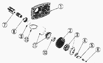
1. Rear Cover, 2. 18T Gear, 3. Taper Roller Bearing, 4. Washer, 5. Lock
Washer, 6. Screw, 7. PTO Shaft, 8. Bushing, 9. PTO Collar, 10. PTO Shim,
11. Taper Roller Bearing, 12. PTO Collar
Flatten the lock washer (5). Remove the screw (6), plain washer, lock
washer (5), washer and straight pin. Tap out the PTO shaft (7) to the
rear. Replace the lock washer with a new one, and be sure to adjust the
turning torque of PTO shaft. Lock the screw with the lock washer after
adjusting the turning torque. Tightening torque Screw - 18.6 to 32 Nm
(13.7 to 23.9 ft-lbs).
Differential Assembly
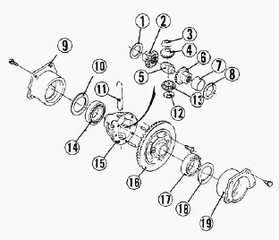
1.Shim, 2.Differential Side Gear, 3.Differential Pinion Collar,
4.Differential Pinion, 5.Thrust Collar, 6.Differential Side Gear, 7.Ring
Gear Bushing, 8.Shim, 9.Differential Bearing Holder (RH),
10.Differential Side Shim, 11.Differential Pinion Shaft, 12.Differential
Pinion Collar, 13.Differential Pinion, 14.Bearing, 15.Differential Case,
16.Ring Gear, 17.Bearing, 18.Differential Side Shim, 19.Differential
Bearing Holder (LH)
Remove the left and right differential bearing holders (19), (9). Take
out the differential assembly from the differential gear case. Install
the differential assembly, noting the number of differential side shims
(10), (18).
________________________________________________________________________________
________________________________________________________________________________________
________________________________________________________________________________________
| KUBOTA TRACTORS SPECIFICATIONS |
________________________________________________________________________________________
________________________________________________________________________________________
________________________________________________________________________________________
________________________________________________________________________________________
________________________________________________________________________________________
________________________________________________________________________________________
________________________________________________________________________________________
________________________________________________________________________________________
________________________________________________________________________________________
________________________________________________________________________________________
________________________________________________________________________________________
________________________________________________________________________________________
________________________________________________________________________________________
________________________________________________________________________________________
________________________________________________________________________________________
| KUBOTA ENGINES DATA AND SERVICE SPECS |
________________________________________________________________________________________
________________________________________________________________________________________
________________________________________________________________________________________
________________________________________________________________________________________
________________________________________________________________________________________
| KUBOTA FRONT END LOADERS |
________________________________________________________________________________________
________________________________________________________________________________________
________________________________________________________________________________________
________________________________________________________________________________________
________________________________________________________________________________________
________________________________________________________________________________________
________________________________________________________________________________________
________________________________________________________________________________________
________________________________________________________________________________________
________________________________________________________________________________________
________________________________________________________________________________________
________________________________________________________________________________________
| KUBOTA TRACTORS TROUBLESHOOTING | ||||
| L235 | L2501 | L2550 | L275 | L3110 |
| L3301 | L35 | L3710 | L3901 | L4310 |
| L5030 | M4700 | M5700 | M6040 | M6800 |
| M8200 | M8540 | M9000 | MX5100 | MX5200 |

 SPECIFICATIONS
 LOADERS
 ENGINES
 MAINTENANCE
 PROBLEMS
 B1241
B1241 B1600
B1600 B1700
B1700 B1750
B1750 B21 Backhoe
 B2150
B2150 B2301
B2301 B2320
B2320 B2530
B2530 B26 Backhoe
 B2601
B2601 B2650HSD
 B3030
B3030 B3350
B3350 B6000
B6000 B6100
B6100 B6200
B6200 B7000
B7000 B7001
B7001 B7100HST
 B7200
B7200 B7500
B7500 B7510
B7510 B7800
B7800 B8200HST
 BX1880
 BX2200
 BX2230
 BX2350
 BX2370
 BX23S
BX23S BX25 TLB
 BX2660
 BX2680
 F3680
F3680 L175
L175 L185
L185 L210
L210 L225
L225 L235
L235 L245
L245 L260
L260 L275
L275 L285
L285 L305
L305 GR2120
 L1501
L1501 L2350
L2350 L2550
L2550 L2800
L2800 L3010
L3010 L3200HST
 L3301
L3301 L3560
L3560 L3800
L3800 L4701
L4701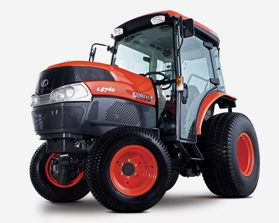 L5740
L5740 M5-091
 M5-111
 M6060
M6060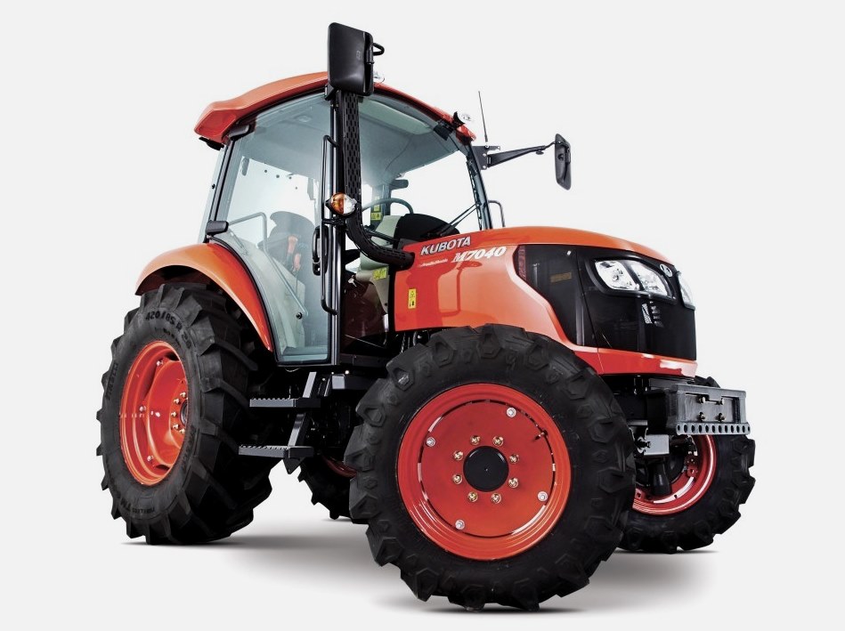 M7040
M7040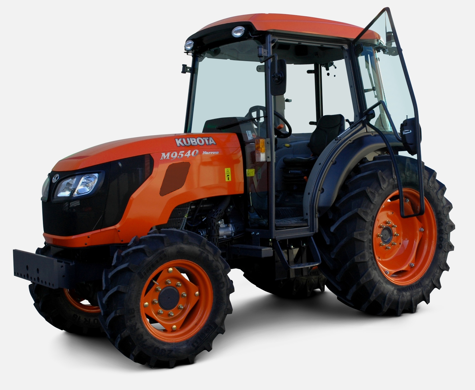 M9540
M9540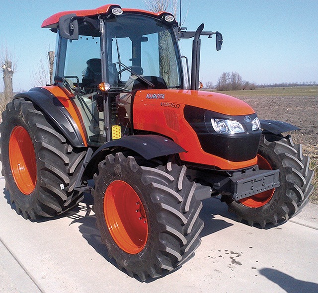 M9960
M9960 MX5100
 D662
D662 D722
D722 D750
D750 D782
D782 D850
D850 D902
D902 D905
D905 D950
D950 D1005
D1005 D1100
D1100 D1105
D1105 D1503
D1503 D1703
D1703 D1803
D1803 V1200
V1200 V1205
V1205 V1305
V1305 V1505
V1505 V2203
V2203 V2403
V2403 Z482
Z482 Z602
Z602 Z750
Z750 Z1100
Z1100 Z1300
Z1300 B1630
B1630 BF400
BF400 BF400G
 LA181
LA181 LA203
LA203 LA211
LA211 LA243
LA243 LA271
LA271 LA272
LA272 LA301
LA301 LA302
LA302 LA304
LA304 LA340
LA340 LA344
LA344 LA351
LA351 LA352
LA352 LA364
LA364 LA401
LA401 LA402
LA402 LA434
LA434 LA463
LA463 LA481
LA481 LA482
LA482 LA504
LA504 LA513
LA513 LA514
LA514 LA524
LA524 LA525
LA525 LA534
LA534 LA555
LA555 LA680
LA680 LA681
LA681 LA682
LA682 LA703
LA703 LA714
LA714 LA723
LA723 LA724
LA724 LA764
LA764 LA765
LA765 LA805
LA805 LA844
LA844 LA852
LA852 LA853
LA853 LA854
LA854 LA1002
 LA1055
 LA1065
 LA1153
 LA1154
 LA1251
 LA1301S
 LA1353
 LA1403
 LA1601S
 LA1854
 LA1944
 LA1953
 LA2253
 LM2605