________________________________________________________________________________
Kubota B7400, B7500, B7510, B7610 - HST Transmission
Kubota B7400, B7500, B7510, B7610 -
Hydrostatic Transmission Components
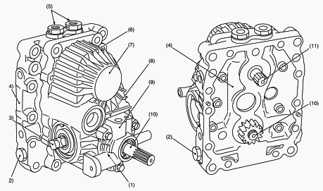
1.Charge Relief Valve, 2.Check and High Pressure Relief Valve,
3.Trunnion Shaft, 4.Center Section, 5.Neutral Valve, 6.Fixed
Displacement Piston Motor, 7.Housing, 8.Variable Displacement Piston
Pump, 9.Charge Pump, 10.Input Shaft (Pump Shaft), 11.Output Shaft
Front Wheel Drive System
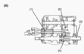
1 - Front Wheel Drive Shaft, 2 - Shifter Gear 20T, 3 - Spiral Bevel
Pinion Shaft, 4 - Gear 13T
Kubota B7400, B7500, B7510, B7610 HST - Oil
Flow
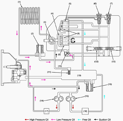
1.Oil Cooler, 2,16-Oil Filter, 3.Charging Pump, 4.Swash Plate, 5.Motor
Cylinder Block, 6.Neutral Valve (Forward), 7.Neutral Valve (Reverse),
8.Piston, 9.Pump Cylinder Block, 10.Charge Relief Valve, 11.Oil
Strainer, 12.Check and High Pressure Relief Valve (Forward), 13.Check
and High Pressure Relief Valve (Reverse), 14.Power Steering Hydraulic
Pump, 15.Main Circuit Hydraulic Pump, 17.Controller of Power Steering,
18.Hydraulic Control Valve, 19.Transmission Case
Kubota B7400, B7500, B7510, B7610 Hydrostatic
Transmission - Control Linkage
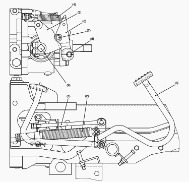
1 - Speed Control Rod Assembly, 2 - Damper, 3 - Speed Control Pedal, 4 -
Spring, 5 - Neutral Holder, 6 - Neutral Holder Arm, 7 - Roller, 8 -
Neutral Adjuster, 9 - Trunnion Shaft
The speed control pedal (3) and the trunnion shaft (9) of variable
swashplate are linked with the speed control rod (1) and the neutral
holder (5). As the front footrest of the pedal is depressed, the
swashplate rotates and forward travelling speed increased. Depressing
the rear footrest increases reverse speed. The roller (7) on the neutral
holder arm (6) is held with spring seats the detent of the neutral
holder (5) so that the neutral holder returns to neutral. Then, the
swashplate is returned to neutral with the neutral holder, when the
pedal is released. The damper (2) connected to the speed control pedal
restricts the movement of the linkage to prevent abrupt operation or
reversing.
Kubota B7400, B7500, B7510, B7610 - HST
Transmission Removal
Roll-Over Protective Structures (ROPS) and 3
Point Hitch
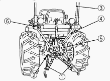
1.Lower Link, 2.3-Point Hitch Shaft, 3.ROPS Top Frame, 4.ROPS Frame,
5.PTO Shaft Cover, 6.Tail Lamp
Disconnect the wire harness of tail lamps. Remove the ROPS frame top
(3). Remove the lower link (1) and the collar from the 3-point hitch
shaft (2). Remove the both sides reflectors (6) with frame. Remove the
both sides fender mounting screws. Remove the PTO shaft cover (5) and
connecting plate. Remove the ROPS left, right frames and 3-point hitch
shaft (2). Connecting plate mounting screw 47.1 to 56.9 Nm / 34.7 to
42.0 ft-Ibs. ROPS frame and frame top mounting bolt and nut 149.1 to
179.5 Nm / 109.9 to 132.4 ft-Ibs. ROPS frame mounting screw - 77.5 to
90.1 Nm / 57.2 to 66.5 ft-Ibs. 3-Point hitch shaft setting screw - 14.7
to 19.6 Nm / 10.8 to 14.5 ft-Ibs. 3-Point hitch shaft setting screw lock
nut - 43.0 to 47.0 Nm / 31.7 to 35.4 ft-Ibs.
Seat, Fender, Steering Wheel, Panel, Step and
Others
Remove the seat, seat adjuster, lowering speed adjusting knob, seat
under cover and fender cover. Remove the position control lever grip,
front wheel drive lever grip and bi-speed turn lever grip (Bi-speed Turn
Type). Remove the fender RH. Remove the mid-PTO gear shift lever grip,
rear PTO shift lever grip and range gear shift lever grip or Hi-Lo shift
lever grip. Remove the fender LH. Loosen the lock nuts and disconnect
the bi-speed turn cable (Bi-speed Turn Type). Remove the fender stay and
bi-speed turn lever as a unit (Bi-speed Turn Type). Remove the cruise
control lever grip, lever guide, tool box and fender stay. Remove the
steering wheel, panel and panel under cover. Remove the fuel tank frame
set screws and fuel tank stay. Remove the clutch and brake springs. Lift
up the fuel tank frame and then remove the steps. Disconnect the speed
set rod, HST release rod and brake pedal link. Place the jack under the
transmission case, and then set the rigid rack under the rear axles.
Remove the tires.
HST Pedal
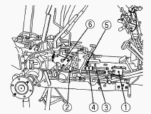
1-Spring Stay, 2-Brake Rod RH, 3-Damper, 4-Speed Control Rod Assembly,
5-Speed Control Rod Screw, 6-Cruise Control Assembly,
Remove the brake springs and spring stay (1). Remove the brake rod RH
(2). Remove the cruise control assembly (6). Remove the damper (3) and
speed control rod assembly (4). Remove the HST pedal. Remove the speed
control rod screw (5) from the neutral holder.
Sub Frame RH, HST Delivery Pipe and Hydraulic
Pipes
Remove the sub frame RH. Remove the pips clamps and pipe joint bolt.
Remover the HST safety switch holder with neutral rod. Disconnect the
HST delivery pipe. Remove the brake rod RH. Remove the connecting pipe.
Remove the HST suction pipe. Remove the sub frame RH. Remove the
hydraulic oil filter assembly and pipes.
Separating Transmission Case from Center Frame
and Hydrostatic Transmission

1-HST Delivery Pipe, 2-Universal Joint, 3-Front Wheel Propeller Shaft,
4-Neutral Spring, 5-Spring Holder, 6-Spring Hook
Separate transmission case and center frame. Remove the propeller shaft,
front wheel drive shaft (1) and HST delivery pipe (2). Remove the
neutral spring (4) and remove the spring holder (5). Separate the HST
from transmission case. Apply liquid gasket (Three Bond 1208D or
equivalent) to joint face of the HST and transmission case. When
inserting the spring pins, face their splits in the direction at a right
angle to the universal joint and propeller shaft. Apply grease to the
spline of the HST pump shaft, front wheel propeller shaft, universal
joint and ball coupling. Spring holder mounting screw 39.2 to 44.1 Nm /
28.9 to 32.5 ft-Ibs. HST and center frame mounting screw and nut - 62.8
to 72.6 Nm / 46.3 to 53.5 ft-Ibs.
Separating Hydraulic Cylinder, Rear Axle Cases
and Others
Remove the front wheel drive lever. Remove the differential lock pedal
support. Remove the top link bracket LH and remove the hydraulic
cylinder. Remove the rear axle case and drawbar frame. Apply liquid
gasket to joint face of the differential case to hydraulic cylinder and
rear axle cases.
Separating Mid-PTO Case, Transmission Case and
Differential Case
Remove the mid-PTO case mounting screws and separate the mid-PTO case
and transmission case. Remove the transmission case mounting screws and
nuts and separate the differential case and transmission case with
middle case as a unit. Apply liquid gasket (Three Bond 1208D or
equivalent) to joint face of the transmission case and differential
case.
Kubota B7500HST, B7510HST, B7610HST -
Transmission Checking And Adjusting
Adjusting Neutral
Disengage the front wheel drive lever (Drive only rear wheels). Lift the
rear of the tractor so that the rear wheels are off the ground and run
the engine at low idling and drive only rear wheels. Slightly loosen the
neutral adjuster setting screw. Rotate the neutral adjuster clockwise so
that rear wheels turn reverse. Then rotate it counterclockwise until
wheels stop completely. Put a mark on the center frame aligning the
groove on neutral adjuster. Rotate the neutral adjuster counterclockwise
so the rear wheels turn forward. Then rotate it clockwise until wheels
stop completely. Put a mark on the center frame aligning the groove on
neutral adjuster. Hold the neutral adjuster so its groove is at the
middle of the marks and tighten the setting screw. When the wheels tend
to turn forward, rotate neutral adjuster clockwise. When the wheels tend
to turn reverse, rotate neutral adjuster counterclockwise.
Charge Relief Pressure and High Relief
Pressure
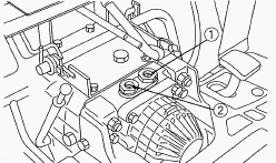
1-Neutral Valve (Forward), 2-Neutral Valve (Reverse)
Remove the lowering speed adjusting knob and dipstick, then remove the
seat under cover. Assemble the HST adaptor A and threaded joint with
O-ring and back up ring. Charge Relief Pressure - Remove the neutral
valve assembly one side (forward (1) or reverse (2)) then install the
assembled HST adaptor A to its neutral valve port. Install the cable and
low pressure gauge to HST adaptor A. Change the range gear shift lever
to Low position. Start the engine and run it at the maximum speed. Read
the low pressure gauge to measure the charge relief pressure. If the
measurement is not same as factory specification, check the charge
relief valve and related hydraulic components. High Relief Pressure -
Remove the neutral valve assembly forward (1), then install the
assembled HST adaptor A to its neutral valve port. Install the cable and
high pressure gauge to HST adaptor A. Change the range gear shift lever
to High position. Start the engine and run it at the maximum speed.
Depress the speed control pedal forward and read the high pressure gauge
to measure the forward high relief pressure. Stop the engine and change
the installation of HST adaptor A and pressure gauge from forward
neutral valve port to reverse. Start engine and repeat above method (4.
and 5.) to measure the reverser high relief pressure. If the measurement
is not same as factory specification, check the high pressure relief
valve and related hydraulic components. Charge relief pressure (Oil
temperature at 50C) - 500 to 800 kPa / 73 to 116 psi. High relief
pressure (Oil temperature at 50C) - 30.9 to 31.9 MPa / 4480 to 4622 psi.
Tightening torque: Neutral valve cap screw - 58.8 to 68.6 Nm / 43.4 to
50.6 ft-Ibs.
Neutral Valve Actuation Test
Disengage the front wheel drive lever. Disconnect the brake rod, one
side. Lift the rear of tractor, one side. Set the engine speed to 1500
rpm. Shift the range gear shift lever to Hi position. Move the HST pedal
from the forward to the neutral position make sure that the tire comes
to stop. Check the same way for the movement from rearward to the
neutral position. In this time, make sure that the neutral range of HST.
If the tire fail to stop or neutral range is point, check the each
neutral valve.
Kubota B7500HST, B7510HST, B7610HST -
Differential Gear Case Disassembly
PTO Shaft
Remove the PTO cover mounting screws and remove the PTO cover assembly.
Apply liquid gasket (Three Bond 12080 or equivalent) to joint face of
differential gear case and PTO cover.
Differential Gear Assembly
Remove the bearing holder mounting screws and remove the bearing holder.
Take out the differential gear assembly. Install the differential gear
assembly, noting the number of shims in the differential case left side
and bearing holder side.
Spiral Bevel Gear
Remove the spiral bevel gear UBS screws. Remove the spiral bevel gear
from differential case. Apply liquid lock to the spiral bevel gear UBS
screws.
Differential Side Gear and Differential Pinion
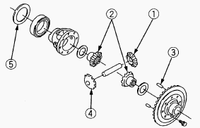
1-Differential Pinion, 2-Differential Side Gear, 3-Dowel Pin,
4-Differential Pinion, 5-Shim
Put parting marks on the differential pinion and the differential side
gear. Tap out the dowel pin. Remove the differential pinion shaft.
Remove the differential pinion, differential side gear and shim. Install
the differential pinion and differential side gear, aligning the parting
marks.
Kubota B7400, B7500, B7510, B7610 -
Hydrostatic Transmission Service
Valve Plate
Check the engagement of the valve plate and the anchor pin. Pushing the
valve plate against the anchor pin, lift it to remove. Check the valve
plate for foreign particles. Clean the valve plate and dry with
compressed air. Check the valve plate for scratches, wear and erosion.
If worn or scored, replace. After checking, coat them with hydrostatic
transmission oil.
Thrust Plate and Swashplate
Check the thrust plate for scratches and excessive wear. If worn or
scored, replace. Check the bearing surface of trunnion shaft
(swashplate) for scratches and excessive wear. If worn or scored,
replace.
Trunnion Shaft Cover
Check the bearing for scratches and excessive wear. If worn or scored,
replace. Check the oil seal and the O-rings for damage. After checking,
coat the bearings with hydrostatic transmission oil, and the oil seal
lip and the O-rings with grease.
Oil Seals and Bearings for Shaft
Remove the internal snap ring and check the oil seals for damage. Check
the bearings for wear. If the bearings are worn, replace. After
checking, coat the bearing with hydrostatic transmission oil and the oil
seal lip with grease.
Check and High Pressure Relief Valve
Check the valve plug and valve for scratches and damage. Check the valve
seat in the port block for damage. Check the spring for breakage and
wear. If anything unusual, replace the check and high pressure relief
valve assembly.
Neutral Valve
Check the holes of the valve body and the neutral valve for clogging. If
clogged, open hole with compressed air. Check the O-rings and the backup
ring for scratches and damage. Check the springs for breakage and wear.
If the valve surface is scored, replace. If anything unusual, replace
Kubota B7500HST, B7510HST, B7610HST -
Differential Gear Service
Clearance between Differential Case (Spiral
Bevel Gear) and Differential Side Gear
Measure the differential side gear boss O.D. with an outside micrometer.
Measure the differential case I.D. and the spiral bevel gear I.D. with
an inside micrometer, and calculate the clearance. If the clearance
exceeds the allowable limit, replace faulty parts. Clearance between
differential case (spiral bevel gear) and differential side gear - 0.025
to 0.066 mm (0.00098 to 0.00260 in). Differential case I.D. - 32.000 to
32.025 mm (1.25984 to 1.26082 in). Spiral bevel gear I.D. - 32.000 to
32.025 mm (1.25984 to 1.26082 in). Differential side gear O.D. - 31.959
to 31.975 mm (1.25823 to 1.25886 in).
Clearance between Differential Pinion Shaft
and Differential Pinion
Measure the differential pinion shaft O.D. with an outside micrometer.
Measure the differential pinion I.D. with an inside micrometer, and
calculate the clearance. If the clearance exceeds the allowable limit,
replace faulty parts. Clearance between differential pinion shaft and
differential pinion - 0.016 to 0.045 mm (0.00063 to 0.00177 in).
Differential pinion I.D. - 16.000 to 16.018 mm (0.62992 to 0.63063 in).
Differential pinion shaft O.D. - 15.973 to 15.984 mm (0.62886 to 0.62929
in).
Backlash between Differential Pinion and
Differential Side Gear
Secure the differential case with a vise. Set the dial indicator (lever
type) with its finger on the tooth of the differential side gear. Press
differential pinion and side gear against the differential case. Hold
the differential pinion and move the differential side gear to measure
the backlash. If the backlash exceeds the allowable limit, adjust with
differential side gear shims. Backlash between differential pinion and
differential side gear - 0.1 to 0.3 mm (0.004 to 0.012 in). Allowable
limit - 0.4 mm (0.016 in).
Backlash between Spiral Bevel Pinion and
Spiral Bevel Gear
Set the dial indicator (lever type) with its finger on the end of spiral
bevel pinion. Move the spiral bevel pinion back and forth to each end
and measure the side clearance. If the side clearance exceeds the
factory specifications, adjust with the shims at front end of spiral
bevel pinion. Set the dial indicator (lever type) with its finger on the
tooth surface of bevel gear. Measure the backlash by fixing the spiral
bevel pinion and moving bevel gear by hand. If the backlash exceeds the
factory specifications, adjust with the shims at bearing holder and
differential case. Adjust the backlash properly by repeating the above
procedure.
________________________________________________________________________________
________________________________________________________________________________________
________________________________________________________________________________________
| KUBOTA TRACTORS SPECIFICATIONS |
________________________________________________________________________________________
________________________________________________________________________________________
________________________________________________________________________________________
________________________________________________________________________________________
________________________________________________________________________________________
________________________________________________________________________________________
________________________________________________________________________________________
________________________________________________________________________________________
________________________________________________________________________________________
________________________________________________________________________________________
________________________________________________________________________________________
________________________________________________________________________________________
________________________________________________________________________________________
________________________________________________________________________________________
________________________________________________________________________________________
| KUBOTA ENGINES DATA AND SERVICE SPECS |
________________________________________________________________________________________
________________________________________________________________________________________
________________________________________________________________________________________
________________________________________________________________________________________
________________________________________________________________________________________
| KUBOTA FRONT END LOADERS |
________________________________________________________________________________________
________________________________________________________________________________________
________________________________________________________________________________________
________________________________________________________________________________________
________________________________________________________________________________________
________________________________________________________________________________________
________________________________________________________________________________________
________________________________________________________________________________________
________________________________________________________________________________________
________________________________________________________________________________________
________________________________________________________________________________________
________________________________________________________________________________________
| KUBOTA TRACTORS TROUBLESHOOTING | ||||
| L235 | L2501 | L2550 | L275 | L3110 |
| L3301 | L35 | L3710 | L3901 | L4310 |
| L5030 | M4700 | M5700 | M6040 | M6800 |
| M8200 | M8540 | M9000 | MX5100 | MX5200 |

 SPECIFICATIONS
 LOADERS
 ENGINES
 MAINTENANCE
 PROBLEMS
 B1241
B1241 B1600
B1600 B1700
B1700 B1750
B1750 B21 Backhoe
 B2150
B2150 B2301
B2301 B2320
B2320 B2530
B2530 B26 Backhoe
 B2601
B2601 B2650HSD
 B3030
B3030 B3350
B3350 B6000
B6000 B6100
B6100 B6200
B6200 B7000
B7000 B7001
B7001 B7100HST
 B7200
B7200 B7500
B7500 B7510
B7510 B7800
B7800 B8200HST
 BX1880
 BX2200
 BX2230
 BX2350
 BX2370
 BX23S
BX23S BX25 TLB
 BX2660
 BX2680
 F3680
F3680 L175
L175 L185
L185 L210
L210 L225
L225 L235
L235 L245
L245 L260
L260 L275
L275 L285
L285 L305
L305 GR2120
 L1501
L1501 L2350
L2350 L2550
L2550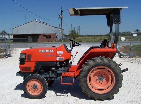 L2800
L2800 L3010
L3010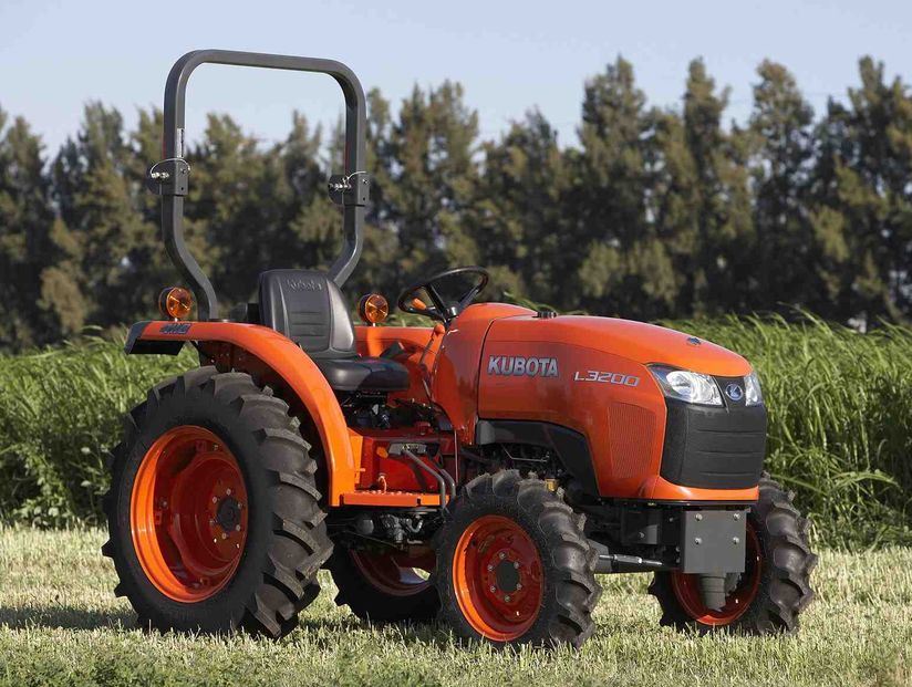 L3200HST
 L3301
L3301 L3560
L3560 L3800
L3800 L4701
L4701 L5740
L5740 M5-091
 M5-111
 M6060
M6060 M7040
M7040 M9540
M9540 M9960
M9960 MX5100
 D662
D662 D722
D722 D750
D750 D782
D782 D850
D850 D902
D902 D905
D905 D950
D950 D1005
D1005 D1100
D1100 D1105
D1105 D1503
D1503 D1703
D1703 D1803
D1803 V1200
V1200 V1205
V1205 V1305
V1305 V1505
V1505 V2203
V2203 V2403
V2403 Z482
Z482 Z602
Z602 Z750
Z750 Z1100
Z1100 Z1300
Z1300 B1630
B1630 BF400
BF400 BF400G
 LA181
LA181 LA203
LA203 LA211
LA211 LA243
LA243 LA271
LA271 LA272
LA272 LA301
LA301 LA302
LA302 LA304
LA304 LA340
LA340 LA344
LA344 LA351
LA351 LA352
LA352 LA364
LA364 LA401
LA401 LA402
LA402 LA434
LA434 LA463
LA463 LA481
LA481 LA482
LA482 LA504
LA504 LA513
LA513 LA514
LA514 LA524
LA524 LA525
LA525 LA534
LA534 LA555
LA555 LA680
LA680 LA681
LA681 LA682
LA682 LA703
LA703 LA714
LA714 LA723
LA723 LA724
LA724 LA764
LA764 LA765
LA765 LA805
LA805 LA844
LA844 LA852
LA852 LA853
LA853 LA854
LA854 LA1002
 LA1055
 LA1065
 LA1153
 LA1154
 LA1251
 LA1301S
 LA1353
 LA1403
 LA1601S
 LA1854
 LA1944
 LA1953
 LA2253
 LM2605