
________________________________________________________________________________
Kubota BX1850, BX1860, BX1870 - LA203 Front End Loader
Kubota LA203 Front End Loader - Hydraulic Operations
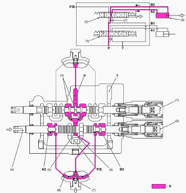
UP position
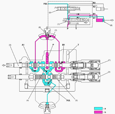
1 - Boom Control Section, 2 - Bucket Control Section, 3 - Spool, 4 -
P.B. Passage 1, 5 - Neutral Passage 1, 6 - Load Check Valve, 7 - Passage
1, 8 - Boom Cylinder, P - P Port (From Pump), T - T Port (To Tank), A1 -
A1 Port (From Boom Cylinder), B1 - B1 Port (To Boom Cylinder), P.B -
P.B. Port (To 3 Hitch), a - Low Pressure, b - High Pressure
When the hydraulic control lever is set to the “UP” position, the spool
(3) of the boom control section (1) moves to the left, which forms oil
passages between passage 1 (7) and B1 port, and between A1 port and P.B.
passage 1 (4). As the oil passage from the neutral passage 1 (5) to the
P.B. passage 1 (4) is closed by the spool (3), the pressure fed oil from
the P port opens the load check valve (6) and flows through the notched
section of the spool (3) and B1 port to extend the boom cylinder (8).
Return oil from the boom cylinder (8) flows from the A1 port through the
passage in the spool (3) and P.B. passage 1 (4) to the bucket control
section (3).
DOWN position
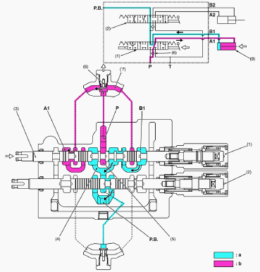
1 - Boom Control Section, 2 - Bucket Control Section, 3 - Spool, 4 -
P.B. Passage 1, 5 - Neutral Passage 1, 6 - Load Check Valve, 7 - Passage
1, 8 - Boom Cylinder, P - P Port (From Pump), T - T Port (To Tank), A1 -
A1 Port (From Boom Cylinder), B1 - B1 Port (To Boom Cylinder), P.B -
P.B. Port (To 3 Hitch), a - Low Pressure, b - High Pressure
When the hydraulic control lever is set to the “DOWN” position, the
spool (3) moves to the right, which forms oil passages between passage 1
(7) and A1 port, and between B1 port and P.B. passage 1 (4). As the oil
passage from the neutral passage 1 (5) to the P.B. passage 1 (4) is
closed by the spool (3), the pressure fed oil from the P port opens the
load check valve (6) and flows through the notched section of the spool
(3) and A1 port to retract the boom cylinder (8). Return oil from the
boom cylinder (8) flows from the B1 port through the passage in the
spool (3) and P.B. passage 1 (4) to the bucket control section (2).
FLOAT position
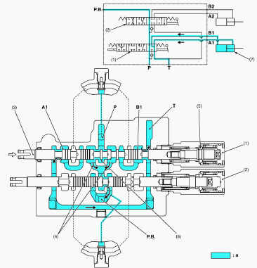
1 - Boom Control Section, 2 - Bucket Control Section, 3 - Spool, 4 -
P.B. Passage 1, 5 - Detent Mechanism, 6 - Neutral Passage 1, 7 - Boom
Cylinder, P - P Port (From Pump), T - T Port (To Tank), A1 - A1 Port, B1
- B1 Port, P.B - P.B. Port (To 3 Hitch), a - Low Pressure
When the hydraulic control lever is set to the “FLOAT” position, the
spool (3) moves further to the right from the “DOWN” position and is
retained by the detent mechanism (5). This forms oil passages among the
A1 port, B1 port and T port. As a result, oil in the boom cylinder (7)
flows freely from the A1 port and B1 port through the T port to the
transmission case. Oil entering the P port flows to the bucket control
section (2) through the neutral passage 1 (6) and P.B. passage 1 (4).
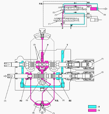
Kubota LA203 Loader - ROLL-BACK position
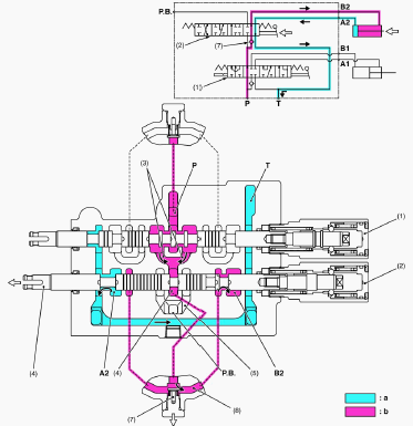
1 - Boom Control Section, 2 - Bucket Control Section, 3 - P.B. Passage
1, 4 - Spool, 5 - Neutral Passage 2, 6 - P.B. Passage 2, 7 - Load Check
Valve, 8 - Passage 2, 9 - Bucket Cylinder, P - P Port (From Pump), T - T
Port (To Tank), P.B - P.B. Port (To 3 Hitch), A2 - A2 Port (From Bucket
Cylinder), B2 - B2 Port (To Bucket Cylinder), a - Low Pressure, b - High
Pressure
When the hydraulic control lever is set to the “ROLL-BACK” position, the
spool (4) of the bucket control section (2) moves to the left, which
forms oil passages between passage 2 (8) and B2 port, and between A2
port and T port. The pressure-fed oil from the P port flows to the
neutral passage 2 (5) through the boom control section (1) and P.B.
passage 1 (3). As the oil passage from the neutral passage 2 (5) to the
P.B. passage 2 (6) is closed by the spool (4), this oil opens the load
check valve (7), and flows through the notched section of the spool (4)
and B2 port to retract the bucket cylinder (9). Return oil from the
bucket cylinder (9) flows to the transmission case through the A2 port
and T port.
DUMP 1 position
1 - Boom Control Section, 2 - Bucket Control Section, 3 - P.B. Passage
1, 4 - Spool, 5 - Neutral Passage 2, 6 - P.B. Passage 2, 7 - Load Check
Valve, 8 - Passage 2, 9 - Bucket Cylinder, P - P Port (From Pump), T - T
Port (To Tank), P.B - P.B. Port (To 3 Hitch), A2 - A2 Port (From Bucket
Cylinder), B2 - B2 Port (To Bucket Cylinder), b - High Pressure
When the hydraulic control lever is set to the “DUMP 1” position, the
spool (4), which forms oil passages among passage 2 (8), A2 port and B2
port. The pressure-fed oil from the P port flows through the boom
control valve, opens the load check valve, and flows to the bucket
cylinder to extend the cylinder through the notched section of the spool
and A2 port. Return oil from the bucket cylinder (9) flows from the B2
port to the passage 2 (8), and flows to the A2 port together with the
pressure-fed oil from the P port. As a result, the dump speed is
increased. The oil pressure of the A2 port and B2 port is identical, but
the bucket cylinder extends by the difference of received pressure area
(cylinder rod part).
DUMP 2 position
1 - Boom Control Section, 2 - Bucket Control Section, 3 - P.B. Passage
1, 4 - Spool, 5 - Neutral Passage 2, 6 - P.B. Passage 2, 7 - Load Check
Valve, 8 - Passage 2, 9 - Bucket Cylinder, P - P Port (From Pump), T - T
Port (To Tank), P.B - P.B. Port (To 3 Hitch), A2 - A2 Port (From Bucket
Cylinder), B2 - B2 Port (To Bucket Cylinder), a - Low Pressure, b - High
Pressure
When the hydraulic control lever is set to the “DUMP 2” position, the
spool (4) of the bucket control section (2) moves to the right of the
bucket control section (2) moves further to the right from the “DUMP 1”
position, which forms oil passages between passage 2 (8) and A2 port,
and between B2 port and T port. The pressure-fed oil from the P port
flows to the neutral passage 2 (5) through the boom control section (1)
and P.B. passage 1 (3). As the oil passage from the neutral passage 2
(5) to the P.B. passage 2 (6) is closed by the spool (4), this oil opens
the load check valve (7) and flows through the notched section of the
spool (4) and B2 port to extend the bucket cylinder (9). Return oil from
the bucket cylinder (9) flows to the transmission case through the B2
port and T port.
Kubota BX1850, BX1860, BX1870 - Boom Cylinder
And Bucket Cylinder
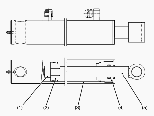
1 - Nut, 2 - Piston, 3 - Cylinder Tube, 4 - Head, 5 - Piston Rod
Both boom cylinder and bucket cylinder consists of a head (4), cylinder
tube (3), piston rod (5), piston (2), and other parts as shown in the
figure above. They are single-rod double acting cylinder in which the
reciprocating motion of the piston is controlled by hydraulic force
applied to both of its ends.
Kubota BX1850, BX1860, BX1870 - Control Valve
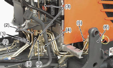
1-Pipe, 2-Cruise Control Rod, 3-Front Loader Control Rod, 4-Arm, 5-Stay,
6-Loader Frame, 7-Valve Stay, 8-Control Valve, 9-Propeller Shaft,
10-Front Loader Control Lever, 11-Rod 1, 12-Rod 2, 13-Rod 3
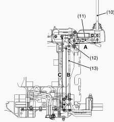
Remove the loader frame (6). Disconnect the cruise control rod (2).
Disconnect the frame loader control rods (3). Remove the brake spring.
Remove the arms (4) from spool end. Remove the stay bolt (5). Remove the
valve stay (7). Disconnect the pipes (1). Remove the control valve (8)
with pipes. After reassembling a valve, check for oil leakage by
starting up engine. When starting up engine, watch out for the rotating
propeller shaft (9). When adjusting the length of rods, make the lever
come to the neutral position. A = 145 mm (5.71 in.), B = 315 mm (12.4
in.), C = 448 mm (17.6 in.).
How to mount LA203 front end loader on Kubota BX1850, BX1860, BX1870
tractor
Side Frame and Hoses
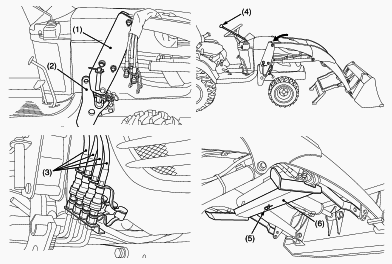
1-Side Frame, 2-Main Frame, 3-Hose, 4-Loader Control Lever, 5-Spring
Pin, 6-Stand
Slowly drive a Kubota BX1850, BX1860, BX1870 tractor between the loader
side frames until the rear portion of both side frames touches the main
frames. Stop the engine. Connect four hoses with couplers to the nipple
on the control valve as indicated with color marks. Then connect the
protective caps and plugs to each other. Start the engine and run at
idle. Slowly move the loader control lever to dump position to lower the
side frames into the main frames and engage the bosses of the main
frames to the guide bosses of the side frames. Then lift the front
wheels slightly with a Kubota LA203 loader. Do not attempt to lift the
front wheels with the stand. Stop the engine. Reinstall the mounting
pins and secure them with the locking rods. Start the engine. Raise the
boom until the stand can be rotated. Stop the engine. Store the stand to
their original positions and secure it with the spring pin. Start the
engine. Lower the boom and level the bucket.
________________________________________________________________________________
________________________________________________________________________________________
 SPECIFICATIONS
 LOADERS
 ENGINES
 MAINTENANCE
 PROBLEMS
________________________________________________________________________________________
| KUBOTA TRACTORS SPECIFICATIONS |
 B1241
B1241 B1600
B1600 B1700
B1700 B1750
B1750 B21 Backhoe
________________________________________________________________________________________
 B2150
B2150 B2301
B2301 B2320
B2320 B2530
B2530 B26 Backhoe
________________________________________________________________________________________
 B2601
B2601 B2650HSD
 B3030
B3030 B3350
B3350 B6000
B6000________________________________________________________________________________________
________________________________________________________________________________________
 B6100
B6100 B6200
B6200 B7000
B7000 B7001
B7001 B7100HST
________________________________________________________________________________________
 B7200
B7200 B7500
B7500 B7510
B7510 B7800
B7800 B8200HST
________________________________________________________________________________________
 BX1880
 BX2200
 BX2230
 BX2350
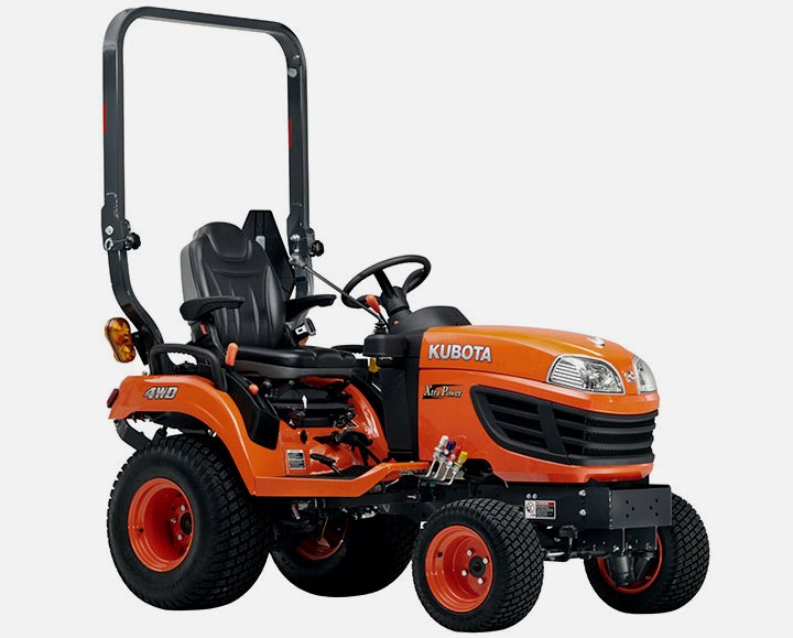 BX2370
________________________________________________________________________________________
 BX23S
BX23S BX25 TLB
 BX2660
 BX2680
 F3680
F3680________________________________________________________________________________________
________________________________________________________________________________________
 L175
L175 L185
L185 L210
L210 L225
L225 L235
L235________________________________________________________________________________________
 L245
L245 L260
L260 L275
L275 L285
L285 L305
L305________________________________________________________________________________________
 GR2120
 L1501
L1501 L2350
L2350 L2550
L2550 L2800
L2800________________________________________________________________________________________
 L3010
L3010 L3200HST
 L3301
L3301 L3400
L3400 L3560
L3560________________________________________________________________________________________
 L3800
L3800 L4701
L4701 L5740
L5740 M5-091
 M5-111
________________________________________________________________________________________
 M6060
M6060 M7040
M7040 M9540
M9540 M9960
M9960 MX5100
________________________________________________________________________________________
| KUBOTA ENGINES DATA AND SERVICE SPECS |
 D662
D662 D722
D722 D750
D750 D782
D782 D850
D850________________________________________________________________________________________
 D902
D902 D905
D905 D950
D950 D1005
D1005 D1100
D1100________________________________________________________________________________________
 D1105
D1105 D1503
D1503 D1703
D1703 D1803
D1803 V1200
V1200________________________________________________________________________________________
 V1205
V1205 V1305
V1305 V1505
V1505 V2203
V2203 V2403
V2403________________________________________________________________________________________
 Z482
Z482 Z602
Z602 Z750
Z750 Z1100
Z1100 Z1300
Z1300________________________________________________________________________________________
| KUBOTA FRONT END LOADERS |
 B1630
B1630 BF400
BF400 BF400G
 LA181
LA181 LA203
LA203________________________________________________________________________________________
 LA211
LA211 LA243
LA243 LA271
LA271 LA272
LA272 LA301
LA301________________________________________________________________________________________
 LA302
LA302 LA304
LA304 LA340
LA340 LA344
LA344 LA351
LA351________________________________________________________________________________________
 LA352
LA352 LA364
LA364 LA401
LA401 LA402
LA402 LA403
LA403________________________________________________________________________________________
 LA434
LA434 LA463
LA463 LA481
LA481 LA482
LA482 LA504
LA504________________________________________________________________________________________
 LA513
LA513 LA514
LA514 LA524
LA524 LA525
LA525 LA534
LA534________________________________________________________________________________________
 LA555
LA555 LA680
LA680 LA681
LA681 LA682
LA682 LA703
LA703________________________________________________________________________________________
 LA714
LA714 LA723
LA723 LA724
LA724 LA764
LA764 LA765
LA765________________________________________________________________________________________
 LA805
LA805 LA844
LA844 LA852
LA852 LA853
LA853 LA854
LA854________________________________________________________________________________________
 LA1002
 LA1055
 LA1065
 LA1153
 LA1154
________________________________________________________________________________________
 LA1251
 LA1301S
 LA1353
 LA1403
 LA1601S
________________________________________________________________________________________
 LA1854
 LA1944
 LA1953
 LA2253
 LM2605
________________________________________________________________________________________
| KUBOTA TRACTORS TROUBLESHOOTING | ||||
| L235 | L2501 | L2550 | L275 | L3110 |
| L3301 | L35 | L3710 | L3901 | L4310 |
| L5030 | M4700 | M5700 | M6040 | M6800 |
| M8200 | M8540 | M9000 | MX5100 | MX5200 |