________________________________________________________________________________
Kubota BX1880, BX2380, BX2680 - Transmission
Kubota BX1880, BX2380, BX2680 - Transmission
Components
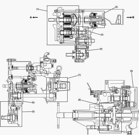
1. Hydrostatic Transmission, 2. PTO Clutch Section, 3. Range Gear Shift
Section, 4. Front Wheel Drive Gear Section, 5. Mid-PTO Section, 6. PTO
Gear Shift Section, 7. Rear PTO Section, 8. Differential Gear Section,
9. Brake Section, A. Front Side, B. Rear Side
Range gear shift lever (Hi-Lo)
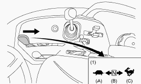
1 - Range gear shift lever (Hi-Lo), A - Low, B - Neutral position, C -
High
You can shift the range gear shift lever only when tractor is completely
stopped. Do not force the range gear shift lever. If it is difficult to
shift the range-gear-shift-lever into the neutral “N” position, you
should attempt the following procedure. Depress the brake pedal firmly
for several seconds. Without reducing the brake pedal force, shift the
range gear shift lever.
If it is difficult to shift the range gear shift lever into the low
position or the high position from the neutral “N” position, you should
attempt the following procedure. Slightly depress the speed control
pedal to rotate the gears inside of transmission. Release the speed
control pedal to the neutral “N” position. Shift the range gear shift
lever.
Front wheel drive lever
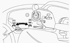
Use the lever to engage the front wheels with the tractor stopped. Shift
the lever to the on position to engage the front wheel drive. To avoid
damage of transmission, when the front wheel drive lever is not smoothly
shifted, slightly depress forward or rearward on the speed control
pedal.
Kubota BX1880, BX2380, BX2680 - Hydrostatic transmission oil flow
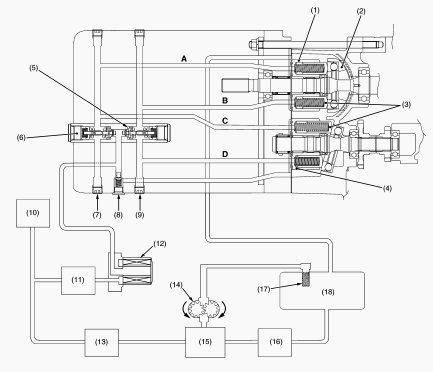
1. Cylinder Block (Pump), 2. Swashplate, 3. Piston, 4. Cylinder Block
(Motor), 5. Check and High Pressure Relief Valve (Forward), 6. Check and
High Pressure Relief Valve (Reverse), 7. High Pressure Relief Port Plug
(Forward), 8. Charge Relief Valve, 9. High Pressure Relief Port Plug
(Reverse), 10. PTO Clutch Valve, 11. PTO Relief Valve, 12. Oil Filter
Cartridge, 13. Power Steering Controller, 14. Hydraulic Pump, 15. Flow
Priority Valve (Hydraulic Control Valve), 16. Position Control Valve,
17. Oil Strainer, 18. Transmission Case, A. A Port, B. B Port, C. C
Port, D. D Port
The pump and motor are joined in a closed hydraulic loop and most of oil
circulates within the main oil circuit. A little oil lubricates and
oozes out from the clearance between the moving parts of the case. Then
oil in the main oil circuit of the HST needs to be supplied a want. The
oil from the power steering circuit flows into the HST for charging. The
charge oil aids smooth operation of pistons for pump and motor. The
charge oil passes through the oil filter cartridge to charge relief
valve port. The rest of oil passes through the charge relief valve into
the HST housing. And overflow oil from HST housing return to the
transmission case.
Kubota BX1880, BX2380, BX2680 - Speed set device
Speed set linkage
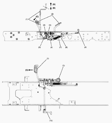
1 - Speed set rod, 2 - Speed control pedal, 3 - Cruise lock, 4 - Cruise
lock, 5 - Cruise plate, 6 - HST pedal link, 7 - Speed change rod, 8 -
Damper, 9 - Trunnion arm, 10 - Release plate, A - Speed set rod OFF, B -
Speed set rod ON, C - Speed control pedal Forward, D - Cruise lock
Locked
When the brake pedal is depressed, the release plate located under the
brake pedal is pushed down. Since the cruise plate rotates, the cruise
lock and between the cruise plate and the HST pedal link are released.
How to use the speed set device
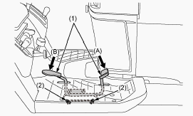
1 - Speed control pedal, 2 - Stopper bolts, A - Forward, B - Reverse
To engage the speed set device - Accelerate speed to desired level using
the speed control pedal. Push and hold the speed set rod downward to on
position. Release the speed control pedal. Release the speed set rod.
Desired speed will be maintained.
To disengage the speed set device - Depress the brake pedal. If you step
on the speed control pedal on the forward acceleration side, the speed
set device will disengage. The speed set device will not operate in
reverse.
Kubota BX1880, BX2380, BX2680 Tractor - PTO System
PTO Clutch Engaged
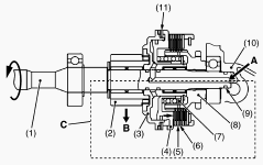
1. HST Pump Shaft, 2. Clutch Gear, 3. Clutch Case, 4. Clutch Piston, 5.
Clutch Plate, 6. Clutch Disc, 7. Spring, 8. Spline Boss, 9. O-ring, 10.
Transaxle Case, 11. Brake Disc, A. From PTO Clutch Valve, B. Power to
PTO Shaft, C. PTO Clutch Engaged
The oil from power steering controller flows into the PTO clutch valve.
When the PTO clutch lever is set at the “Engaged” position, the PTO
clutch valve rotates. Oil flows from the oil line through transmission
case to the PTO clutch pack. Oil entering the clutch pack pushes the
clutch piston (4) to engage the clutch pack. Power is transmitted from
the HST pump shaft (1) through the PTO clutch to the clutch gear (2) and
the PTO shafts.
PTO Clutch Disengaged
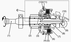
1. HST Pump Shaft, 2. Clutch Gear, 3. Clutch Case, 4. Clutch Piston, 5.
Clutch Plate, 6. Clutch Disc, 7. Spring, 8. Spline Boss, 9. O-ring, 10.
Transaxle Case, 11. Brake Plate, 12. Brake Disc, C. PTO Clutch
Disengaged
When the PTO clutch lever is set at the “Disengaged” position, the PTO
clutch valve closes the oil passage to the PTO clutch pack. The oil in
the PTO clutch pack drain into the transaxle case (10). Thus the clutch
piston (4) is pushed back by the spring (7). When the clutch piston (4)
is pushed back by the spring (7), the brake plate (11) is also moved to
contract the brake disc (12) so as to stop the rotation and drag of the
PTO shafts.
Stationary PTO
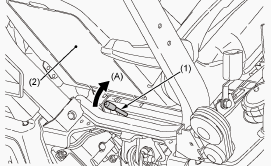
1 - Seat lock lever, 2 - Seat, A - Unlock
To park the tractor and use the PTO system for chipper or pump, for
example, start the PTO system in the following steps. Apply the parking
brake and place blocks at the tires. Make sure that all shift levers are
in their neutral position, and start the engine. Set the PTO select
lever to the Rear-PTO (Rear only) position. Get off the seat and tilt up
it. Move the seat lock lever behind the seat frame in the arrow
direction in the following figure to release the seat lock, and lift the
seat forward. 6. Set the PTO clutch lever to the on (engage) position.
Set the engine speed appropriately to provide recommend rear PTO speed.
Kubota BX1880, BX2380, BX2680 - PTO select lever
Mid PTO
To use the mid PTO, shift the PTO select lever to the mid PTO position
and the PTO clutch lever to the on position. The mid PTO is available
for approved implements.
Mid-Rear PTO
To use the mid PTO and the rear PTO at the same time, shift the PTO
select lever to the mid-rear PTO position and the PTO clutch lever to
the on position.
Rear PTO
To use the rear PTO, shift the PTO select lever to the rear PTO position
and the PTO clutch lever to the on position.
PTO drive shaft
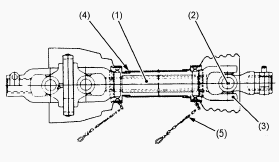
1 - Inner and outer sliding profile tubes, 2 - Journal cross assy, 3 -
Fitting yoke, 4 - Safety guard (in, out), 5 - Chain
When using a PTO drive shaft, read the operator's manual of the
implement before operating the implement. If it is necessary for using
the PTO drive shaft, adjust the length of it. Make sure that the PTO
drive shaft is securely connected at both ends before operating it.
PTO clutch lever
The PTO clutch lever engages or disengages the PTO clutch which gives
the PTO independent control. When you engage the PTO clutch, shift the
PTO clutch lever slowly to avoid damage to the PTO clutch and implement.
Shift the PTO clutch lever to the on position to engage the PTO clutch.
Shift the PTO clutch lever to the off position to disengage the PTO
clutch. The tractor engine will not start if the PTO clutch lever is in
the engaged ON position. When you stand up from the seat with the PTO
clutch lever at the engaged ON position, the engine will stop regardless
of the position of the PTO select lever.
Adjusting the length of PTO drive shaft
To adjust the length of the PTO-drive-shaft, refer to the following
instructions. To adjust the inner and outer guard tubes, hold the half
shafts next to each other in the shortest working position, and mark the
half shafts in the shortest working position of the inner and outer
guard tubes. Shorten the inner and outer guard tubes to the marked
position equally. Shorten the inner and outer sliding profile tubes by
the same length as the inner and outer guard tubes. Round all sharp
edges off, remove burrs, and grease sliding profiles.
Kubota BX1880, BX2380, BX2680 - Transmission Maintenance
Transmission fluid level check
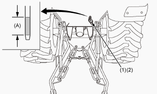
1 - Oil inlet, 2 - Dipstick, A - Transmission fluid level is acceptable
within this range
To check the transmission fluid level, check the dipstick as the
following procedure. Draw out the dipstick. Wipe the dipstick clean.
Replace the dipstick. Draw the dipstick out again. Check to see that the
transmission fluid level lies between the two notches. If the fluid
level is too low, add new fluid to the prescribed level at the oil
inlet.
Transmission oil filter replacement
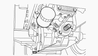
Remove the transmission oil filter. Put a film of clean transmission oil
on rubber seal of new oil filter. Tighten the transmission oil filter
quickly until it contacts the mounting surface. Tighten the transmission
oil filter by hand an additional 1/2 turn only. After the new oil filter
has been replaced, the transmission fluid level will decrease a little.
Make sure that the transmission fluid does not leak through the seal,
and check the fluid level. Check the dipstick and refill with oil to
prescribed level. Properly dispose of used oil.
Transmission fluid changing
Transmission fluid capacity - 11.3 L. To drain the used transmission
fluid, remove the drain plug at the bottom of the transmission case and
drain fluid completely into the oil pan. After draining the transmission
fluid, reinstall the drain plug. Clean the transmission strainer. Fill
with new transmission fluid up to the upper notch on the dipstick. After
running the engine for a few minutes, stop it and check fluid level
again. If the transmission fluid level is lower, add it to the
prescribed level. Properly dispose of used transmission fluid.
Transmission strainer cleaning
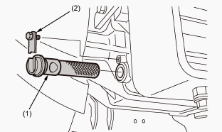
1 - Transmission strainer, 2 - Filter plate
When changing the transmission fluid, disassemble and rinse the
transmission strainer with nonflammable solvent to completely clean off
filings. When reassembling the transmission strainer, be careful not to
damage the parts. Since the fine filings in the oil can damage the
precision component parts of the hydraulic system, the end of the
suction line is provided with an oil strainer.
________________________________________________________________________________
________________________________________________________________________________________
________________________________________________________________________________________
| KUBOTA TRACTORS SPECIFICATIONS |
________________________________________________________________________________________
________________________________________________________________________________________
________________________________________________________________________________________
________________________________________________________________________________________
________________________________________________________________________________________
________________________________________________________________________________________
________________________________________________________________________________________
________________________________________________________________________________________
________________________________________________________________________________________
________________________________________________________________________________________
________________________________________________________________________________________
________________________________________________________________________________________
________________________________________________________________________________________
________________________________________________________________________________________
________________________________________________________________________________________
| KUBOTA ENGINES DATA AND SERVICE SPECS |
________________________________________________________________________________________
________________________________________________________________________________________
________________________________________________________________________________________
________________________________________________________________________________________
________________________________________________________________________________________
| KUBOTA FRONT END LOADERS |
________________________________________________________________________________________
________________________________________________________________________________________
________________________________________________________________________________________
________________________________________________________________________________________
________________________________________________________________________________________
________________________________________________________________________________________
________________________________________________________________________________________
________________________________________________________________________________________
________________________________________________________________________________________
________________________________________________________________________________________
________________________________________________________________________________________
________________________________________________________________________________________
| KUBOTA TRACTORS TROUBLESHOOTING | ||||
| L235 | L2501 | L2550 | L275 | L3110 |
| L3301 | L35 | L3710 | L3901 | L4310 |
| L5030 | M4700 | M5700 | M6040 | M6800 |
| M8200 | M8540 | M9000 | MX5100 | MX5200 |

 SPECIFICATIONS
 LOADERS
 ENGINES
 MAINTENANCE
 PROBLEMS
 B1241
B1241 B1600
B1600 B1700
B1700 B1750
B1750 B21 Backhoe
 B2150
B2150 B2301
B2301 B2320
B2320 B2530
B2530 B26 Backhoe
 B2601
B2601 B2650HSD
 B3030
B3030 B3350
B3350 B6000
B6000 B6100
B6100 B6200
B6200 B7000
B7000 B7001
B7001 B7100HST
 B7200
B7200 B7500
B7500 B7510
B7510 B7800
B7800 B8200HST
 BX1880
 BX2200
 BX2230
 BX2350
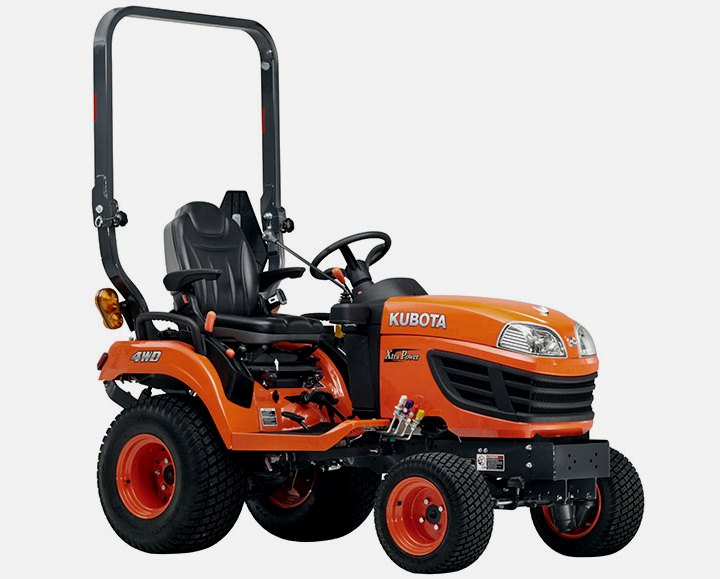 BX2370
 BX23S
BX23S BX25 TLB
 BX2660
 BX2680
 F3680
F3680 L175
L175 L185
L185 L210
L210 L225
L225 L235
L235 L245
L245 L260
L260 L275
L275 L285
L285 L305
L305 GR2120
 L1501
L1501 L2350
L2350 L2550
L2550 L2800
L2800 L3010
L3010 L3200HST
 L3301
L3301 L3560
L3560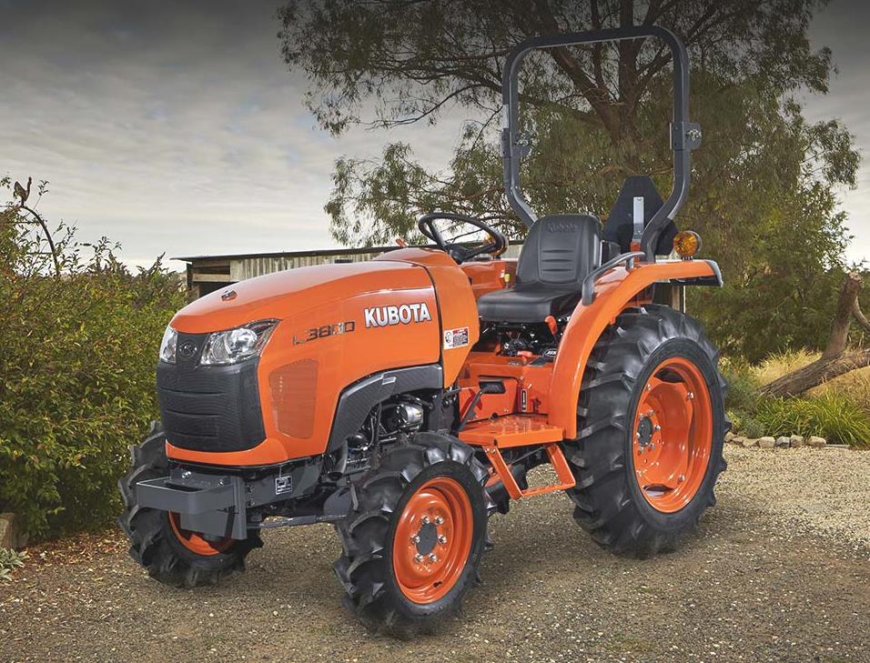 L3800
L3800 L4701
L4701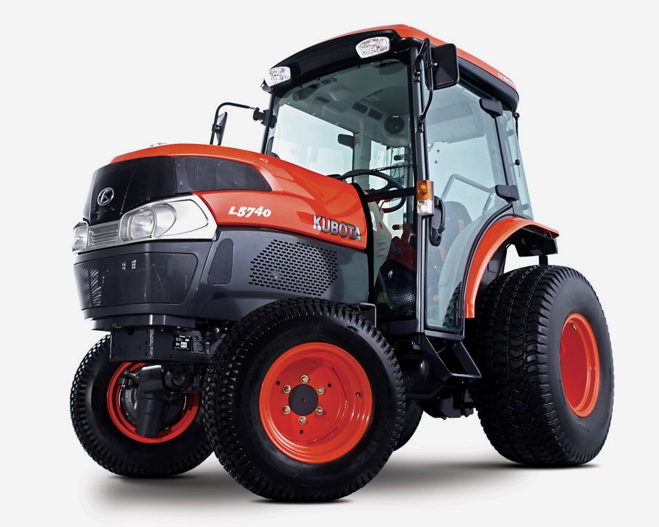 L5740
L5740 M5-091
 M5-111
 M6060
M6060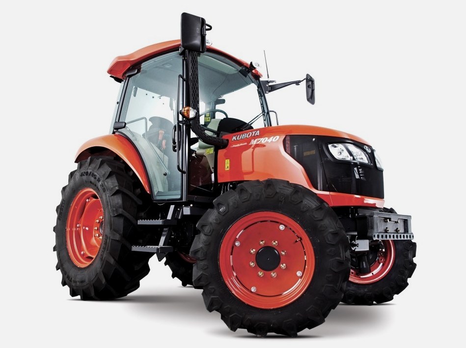 M7040
M7040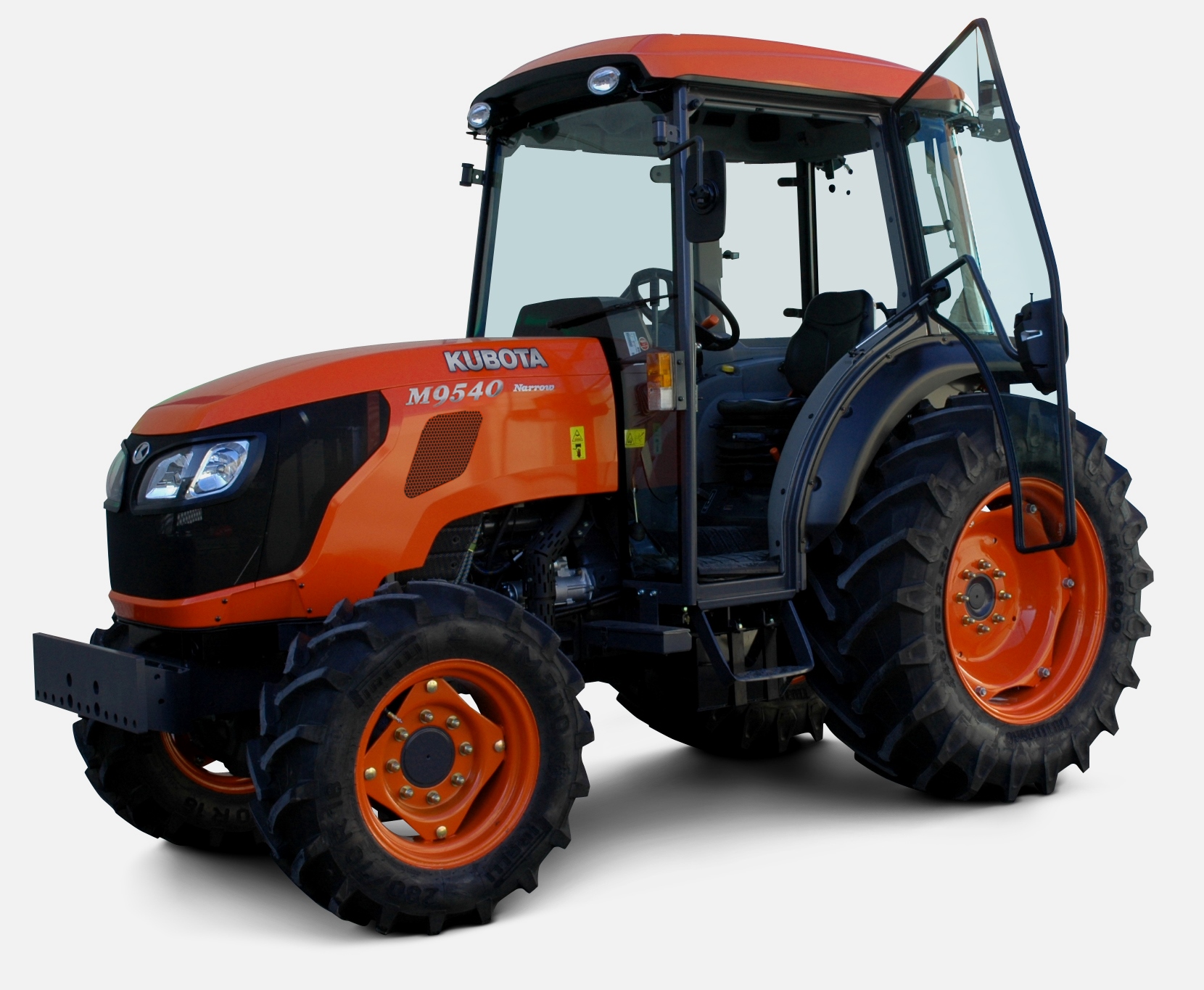 M9540
M9540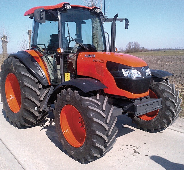 M9960
M9960 MX5100
 D662
D662 D722
D722 D750
D750 D782
D782 D850
D850 D902
D902 D905
D905 D950
D950 D1005
D1005 D1100
D1100 D1105
D1105 D1503
D1503 D1703
D1703 D1803
D1803 V1200
V1200 V1205
V1205 V1305
V1305 V1505
V1505 V2203
V2203 V2403
V2403 Z482
Z482 Z602
Z602 Z750
Z750 Z1100
Z1100 Z1300
Z1300 B1630
B1630 BF400
BF400 BF400G
 LA181
LA181 LA203
LA203 LA211
LA211 LA243
LA243 LA271
LA271 LA272
LA272 LA301
LA301 LA302
LA302 LA304
LA304 LA340
LA340 LA344
LA344 LA351
LA351 LA352
LA352 LA364
LA364 LA401
LA401 LA402
LA402 LA434
LA434 LA463
LA463 LA481
LA481 LA482
LA482 LA504
LA504 LA513
LA513 LA514
LA514 LA524
LA524 LA525
LA525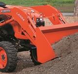 LA534
LA534 LA555
LA555 LA680
LA680 LA681
LA681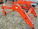 LA682
LA682 LA703
LA703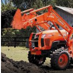 LA714
LA714 LA723
LA723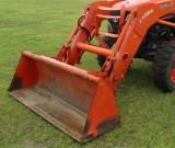 LA724
LA724 LA764
LA764 LA765
LA765 LA805
LA805 LA844
LA844 LA852
LA852 LA853
LA853 LA854
LA854 LA1002
 LA1055
 LA1065
 LA1153
 LA1154
 LA1251
 LA1301S
 LA1353
 LA1403
 LA1601S
 LA1854
 LA1944
 LA1953
 LA2253
 LM2605