
________________________________________________________________________________
Kubota BX2350, BX2370, BX2380 Engine - Service and Checking
Kubota BX2350, BX2370, BX2380 tractors are equipped with a D902
three-cylinder diesel engine.
Kubota BX2350, BX2370, BX2380 - Fuel System
Injection Timing
Remove the injection pipes. Remove the engine stop solenoid. Turn the
flywheel counterclockwise (viewed from flywheel side) until the fuel
fills up to the hole of the delivery valve holder for No. 1 cylinder.
After the fuel fills up to the hole of the delivery valve holder for
No.1 cylinder, turn back (clockwise) the flywheel around 1.57 rad (90°).
Turn the flywheel counterclockwise to set at around 0.44 rad (25°)
before T.D.C. Slowly turn the flywheel counterclockwise and stop turning
when the fuel begins to come up, to get the present injection timing.
Check to see the degree on flywheel. The flywheel has mark 1TC, 10 and
20 for the crank angle before the top dead center of No. 1 cylinder.
Check to see if the timing angle on the flywheel is aligned with the
alignment mark. If injection timing is out of adjustment, readjust the
timing with shims. Injection timing - 0.33 to 0.37 rad (19 to 21°)
before T.D.C.
Fuel Tightness of Pump Element
Remove the engine stop solenoid. Remove the injection pipes and glow
plugs. Install the injection pump pressure tester to the injection pump.
Install the injection nozzle jetted with the proper injection pressure
to the injection pump pressure tester. Set the speed control lever to
the maximum speed position. Run the starter to increase the pressure.
Fuel Tightness of Delivery Valve
Remove the engine stop solenoid. Remove the injection pipes and glow
plugs. Set a pressure tester to the fuel injection pump. Install the
injection nozzle jetted with the proper injection pressure to the
injection pump pressure tester. Run the starter to increase the
pressure. Stop the starter when the fuel jets from the injection nozzle.
After that, turn the flywheel by hands and raise the pressure to approx.
13.73 MPa (140 kgf/cm2, 1991 psi). Now turn the flywheel back about half
a turn (to keep the plunger free). Maintain the flywheel at this
position and clock the time taken for the pressure to drop from 13.73 to
12.75 MPa (from 140 to 130 kgf/cm2, from 1991 to 1849 psi). Measure the
time needed to decrease the pressure from 13.73 to 12.75 MPa (140 to 130
kgf/cm2, 1991 to 1849 psi).
Kubota BX2350, BX2370, BX2380 - Fuel Injection
Pressure
Set the injection nozzle to a nozzle tester. Slowly move the tester
handle to measure the pressure at which fuel begins jetting out from the
nozzle. If the measurement is not within the factory specifications,
replace the adjusting washer in the nozzle holder to adjust it. Pressure
variation with 0.025 mm (0.0010 in.) difference of adjusting washer
thickness. Approx. 588 kPa (6.0 kgf/cm2, 85 psi).
Cleaning Fuel Filter (Element Type only)
Close the fuel cock. Unscrew the retaining ring and remove the filter
cup, and rinse the inside with kerosene. Take out the element and dip it
in the kerosene to rinse. After cleaning, reassemble the fuel filter,
keeping out dust and dirt. Bleed the fuel system. If dust and dirt enter
the fuel, the fuel injection pump and injection nozzle will wear
quickly. To prevent this, be sure to clean the fuel filter cup
periodically.
Replacing Fuel Filter Cartridge (Cartridge
Type)
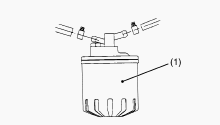
Water and dust in fuel are collected in the filter cartridge. So, change
the filter cartridge every 400 hours service. Remove the used filter
cartridge with filter wrench. Apply a thin film of fuel to the surface
of new filter cartridge gasket before screwing on. Then tighten enough
by hand. Loosen the air vent plug to let the air out. Start Kubota D902
engine and check for fuel leakage.
Replacing Fuel Filter Element (Element Type)
Close the fuel cock. Unscrew the retaining ring and remove the filter
cup, and rinse the inside with kerosene. Replace the filter element.
Reassemble the fuel filter, keeping out dust and dirt. Bleed the fuel
system.
Checking Injection Pump
Remove the engine stop solenoid. Remove the injection pipes and glow
plugs. Install the injection pump pressure tester to the injection pump.
Install the injection nozzle jetted with the proper injection pressure
to the injection pump pressure tester. Set the speed control lever to
the maximum speed position. Run the starter to increase the pressure. If
the pressure can not reach the allowable limit, replace the pump with
new one or repair.
Kubota BX2350, BX2370, BX2380 - Electrical
System
Battery Voltage
Stop Kubota D902 engine. Measure the voltage with a circuit tester
between the battery terminals. If the battery voltage is less than the
factory specification, check the battery specific gravity and recharge
the battery.
Magnetic Switch Test
Disconnect the battery negative cable from the battery. Disconnect the
battery positive cable from the battery. Disconnect the leads from the
starter B terminal. Remove the starter from the engine. Connect a jumper
lead from the starter S terminal to the battery positive terminal.
Connect a jumper lead momentarily between the starter’s body and the
battery negative terminal. If the pinion gear does not pop out, the
magnetic switch is failure. Repair or replace the starter.
Alternator on Unit Test
Before alternator on unit test, check the battery terminal connections,
circuit connection, fan belt tension, charging indicator lamp, fuses on
the circuit, and abnormal noise from the alternator. Prepare full
charged battery for the test. Start the engine. When the engine is
operating measure the voltage between two battery terminals. If the
voltage is between 13.8 V and 14.8 V, the alternator is operating
normally.
Engine Stop Solenoid Test (Energize to Run
Type)
Disconnect the 3P connector from the engine stop solenoid wiring
harness. Remove the engine stop solenoid from the engine. Connect the
jumper leads from the pulling coil terminal to the switch, and from
switch to the battery positive terminal. Connect the jumper leads from
the holding coil terminal to the switch, and from switch to the battery
positive terminal. Connect the jumper leads from the ground terminal to
the battery negative terminal. When the switch is turn on, the plunger
pull into the solenoid body and then the plunger comes out within
approximately 1.2 seconds. Turn on the switch then turn on the switch,
the plunger pull into the solenoid body and it keeps in holding position
after turn off the switch. If the plunger is not attracted, the engine
stop solenoid is faulty.
Replacing Battery
Disconnect the negative terminal and positive terminal. Remove the
battery holder. Remove the used battery. Replace the new battery.
Tighten the battery holder. Connect the positive terminal. Connect the
negative terminal.
Kubota BX2350, BX2370, BX2380 - Basic Engine
Parts
Compression Pressure
Run Kubota D902 engine until it is warmed up. Stop the engine. Remove
the air cleaner, the muffler and all injection nozzles. Set a
compression tester with the adaptor to the nozzle hole. After making
sure that the stop lever is set at the stop position (non-injection),
run the engine with the starter and measure the compression pressure.
Repeat steps 4 and 5 for each cylinder. If the measurement is below the
allowable limit, apply a small amount of oil to the cylinder wall
through the glow plug hole (or nozzle hole) and measure the compression
pressure again. If the compression pressure is still less than the
allowable limit, check the top clearance, valve clearance and cylinder
head. If the compression pressure increases after applying oil, check
the cylinder wall and piston rings. Check the compression pressure with
the specified valve clearance.
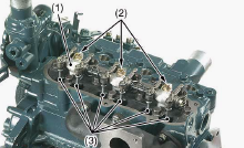
Checking Valve Clearance
Valve clearance must be checked and adjusted when engine is cold. Remove
the cylinder head cover and the glow plugs. Align the 1TC mark on the
flywheel and alignment mark on the rear end plate so that the No. 1
piston comes to the compression top dead center. Check the following
valve clearance marked using a feeler gauge. If the clearance is not
within the factory specifications, adjust with the adjusting screw. Then
turn the flywheel 6.28 rad (360°), and align the 1TC mark on the
flywheel and alignment mark on the rear end plate so that the No. 1
piston comes to the overlap position. Check the following valve
clearance marked using a feeler gauge. If the clearance is not within
the factory specifications, adjust with the adjusting screw. Intake and
exhaust valve clearance (cold) - 0.145 to 0.185 mm / 0.00571 to 0.00728
in.
Cylinder Head and Valves
Top Clearance - Remove the cylinder head (Do not attempt to remove the
cylinder head gasket). Move the piston up and stick a strip of fuse 1.5
mm dia. (0.059 in. dia.), 5 to 7 mm long (0.197 to 0.276 in. long) on
the piston head at three positions with grease so as to avoid the intake
and exhaust valves and the combustion chamber ports. Lower the piston,
and install the cylinder head and tighten the cylinder head screws to
the specified torque. Turn the flywheel until the piston exceeds top
dead center. Remove the cylinder head, and measure the thickness of the
squeezed fuses. If the measurement is not within the factory
specifications, check the oil clearance between the crankpin and
crankpin bearing and between the piston pin and small end bushing. Top
clearance - 0.50 to 0.70 mm / 0.0197 to 0.0276 in.
Cylinder Head Surface Flatness
Clean the cylinder head surface. Place a straightedge on the cylinder
head’s four sides and two diagonal. Measure the clearance with a
thickness gauge. If the measurement exceeds the allowable limit, correct
it with a surface grinder. Do not place the straightedge on the
combustion chamber. Be sure to check the valve recessing after
correcting. Cylinder head surface flatness - Allowable limit 0.05 mm /
0.0020 in.
Cylinder Head Flaw
Prepare an air spray red check. Clean the surface of the cylinder head
with detergent. Spray the cylinder head surface with the red permeative
liquid. Leave it five to ten minutes after spraying. Wash away the read
permeative liquid on the cylinder head surface with the detergent. Spray
the cylinder head surface with white developer. If flawed, it can be
identified as red marks.
Kubota BX2350, BX2370, BX2380 - Valve
Recessing
Clean the cylinder head surface, valve face and valve seat. Insert the
valve into the valve guide. Measure the valve recessing with a depth
gauge. If the measurement exceeds the allowable limit, replace the
valve. If it still exceeds the allowable limit after replacing the
valve, replace the cylinder head. Valve recessing (Intake and exhaust) -
0.10 (protrusion) to 0.10 (recessing) mm / 0.0039 (protrusion) to 0.0039
(recessing) in.
Clearance between Valve Stem and Valve Guide
Remove carbon from the valve guide section. Measure the valve stem O.D.
with an outside micrometer. Measure the valve guide I.D. with a small
hole gauge, and calculate the clearance. If the clearance exceeds the
allowable limit, replace the valves. If it still exceeds the allowable
limit, replace the valve guide. Clearance between valve stem and valve
guide - 0.030 to 0.057 mm / 0.00118 to 0.00224 in. Valve stem O.D. -
5.968 to 5.980 mm / 0.23496 to 0.23543 in. Valve guide I.D. - 6.010 to
6.025 mm / 0.23661 to 0.23720 in.
Replacing Valve Guide
Press out the used valve guide using a valve guide replacing tool. Clean
a new valve guide and valve guide bore, and apply engine oil to them.
Press in a new valve guide using a valve guide replacing tool. Ream
precisely the I.D. of the valve guide to the specified dimension. Valve
guide I.D. (Intake and exhaust) - 6.010 to 6.025 mm / 0.23661 to 0.23720
in.
Valve Seating
Coat the valve face lightly with prussian blue and put the valve on its
seat to check the contact. If the valve does not seat all the way around
the valve seat or the valve contact is less than 70 %, correct the valve
seating as follows. If the valve contact does not comply with the
reference value, replace the valve or correct the contact of valve
seating.
Correcting Valve and Valve Seat
Before correcting the valve and seat, check the valve stem and the I.D.
of valve guide section, and repair them if necessary. After correcting
the valve seat, be sure to check the valve recessing. Correct the valve
with a valve refacer. Slightly correct the seat surface with a 0.785 rad
(45°) valve seat cutter. Fitting the valve, check the contact position
of the valve face and seat surface with prussian blue. Grind the upper
surface of the seat with a 0.262 rad (15°) valve seat cutter until the
valve seat touches to the center of the valve face. Grind the seat with
a 0.785 rad (45°) valve seat cutter again, and visually recheck the
contact between the valve and seat. Repeat steps 3 and 4 until the
correct contact is achieved. Continue lapping until the seated rate
becomes more than 70 % of the total contact area.
Kubota BX2350, BX2370, BX2380 - Valve Lapping
Apply compound evenly to the valve lapping surface. Insert the valve
into the valve guide. Lap the valve onto its seat with a valve flapper
or screwdriver. After lapping the valve, wash the compound away and
apply oil, then repeat valve lapping with oil. Apply prussian blue to
the contact surface to check the seated rate. If it is less than 70 %,
repeat valve lapping again.
Free Length and Tilt of Valve Spring
Measure the free length of valve spring with vernier calipers. If the
measurement is less than the allowable limit, replace it. Put the valve
spring on a surface plate, place a square on the side of the valve
spring. Check to see if the entire side is in contact with the square.
Rotate the valve spring and measure the maximum tilt. If the measurement
exceeds the allowable limit, replace it. Check the entire surface of the
valve spring for scratches. If there is any defect, replace it. Tilt -
Allowable limit 1.2 mm / 0.047 in. Free length - 31.3 to 31.8 mm / 1.232
to 1.252 in.
Valve Spring Setting Load
Place the valve spring on a tester and compress it to the same length it
is actually compressed the engine. Read the compression load on the
gauge. If the measurement is less than the allowable limit, replace it.
Oil Clearance between Rocker Arm and Rocker
Arm Shaft
Measure the rocker arm shaft O.D. with an outside micrometer. Measure
the rocker arm I.D. with an inside micrometer, and then calculate the
oil clearance. If the oil clearance exceeds the allowable limit, replace
the rocker arm and measure the oil clearance again. If it still exceeds
the allowable limit, replace also the rocker arm shaft. Oil clearance
between rocker arm and rocker arm shaft - 0.016 to 0.045 mm / 0.00063 to
0.00177 in. Rocker arm shaft O.D. - 10.473 to 10.484 mm / 0.41232 to
0.41276 in. Rocker arm I.D. - 10.500 to 10.518 mm / 0.41339 to 0.41410
in.
Push Rod Alignment
Place the push rod on V blocks. Measure the push rod alignment. If the
measurement exceeds the allowable limit, replace the push rod. Push rod
alignment - Allowable limit 0.25 mm / 0.0098 in.
Oil Clearance between Tappet and Tappet Guide
Bore
Measure the tappet O.D. with an outside micrometer. Measure the I.D. of
the tappet guide bore with a cylinder gauge, and calculate the oil
clearance. If the oil clearance exceeds the allowable limit or the
tappet is damaged, replace the tappet. Oil clearance between tappet and
tappet guide bore - 0.016 to 0.052 mm / 0.00063 to 0.00205 in. Tappet
O.D. - 17.966 to 17.984 mm / 0.70732 to 0.70803 in. Tappet guide bore
I.D. - 18.000 to 18.018 mm / 0.70866 to 0.70937 in.
Kubota BX2350, BX2370, BX2380 - Timing Gears
Timing Gear Backlash
Set a dial indicator (lever type) with its tip on the gear tooth. Move
the gear to measure the backlash, holding its mating gear. If the
backlash exceeds the allowable limit, check the oil clearance of the
shaft and the gear. If the oil clearance is proper, replace the gear.
Backlash between idle gear and crank gear - 0.043 to 0.124 mm / 0.00169
to 0.00488 in. Backlash between idle gear and cam gear - 0.047 to 0.123
mm / 0.00185 to 0.00484 in. Backlash between idle gear and injection
pump gear - 0.046 to 0.124 mm / 0.00181 to 0.00488 in. Backlash between
oil pump drive gear and crank gear - 0.041 to 0.123 mm / 0.00161 to
0.00484 in.
Idle Gear Side Clearance
Set a dial indicator with its tip on the idle gear. Measure the side
clearance by moving the idle gear to the front and rear. If the
measurement exceeds the allowable limit, replace the idle gear collar.
Idle gear side clearance - 0.20 to 0.51 mm / 0.0079 to 0.0201 in.
Camshaft Side Clearance
Set a dial indicator with its tip on the camshaft. Measure the side
clearance by moving the cam gear to the font and rear. If the
measurement exceeds the allowable limit, replace the camshaft stopper.
Camshaft side clearance - 0.15 to 0.31 mm / 0.0059 to 0.0122 in.
Camshaft Alignment
Support the camshaft with V blocks on the surface plate at both end
journals. Set a dial indicator with its tip on the intermediate journal.
Measure the camshaft alignment. If the measurement exceeds the allowable
limit, replace the camshaft. Camshaft alignment - Allowable limit 0.01
mm / 0.0004 in.
Cam Height
Measure the height of the cam at its highest point with an outside
micrometer. If the measurement is less than the allowable limit, replace
the camshaft. Cam height of intake and exhaust - 26.88 mm / 1.0583 in.
Oil Clearance of Camshaft Journal
Measure the camshaft journal O.D. with an outside micrometer. Measure
the cylinder block bore I.D. for camshaft with a inside micrometer, and
calculate the oil clearance. If the oil clearance exceeds the allowable
limit, replace the camshaft. Oil clearance of camshaft journal - 0.050
to 0.091 mm / 0.00197 to 0.00358 in. Camshaft journal O.D. - 32.934 to
32.950 mm / 1.29661 to 1.29724 in. Camshaft Bearing I.D. (Cylinder block
bore I.D.) - 33.000 to 33.025 mm / 1.29921 to 1.30020 in.
Oil Clearance between Idle Gear Shaft and Idle
Gear Bushing
Measure the idle gear shaft O.D. with an outside micrometer. Measure the
idle gear bushing I.D. with an inside micrometer, and calculate the oil
clearance. If the oil clearance exceeds the allowable limit, replace the
bushing. If it still exceeds the allowable limit, replace the idle gear
shaft. Oil clearance between idle gear shaft and idle gear bushing 0.020
to 0.084 mm / 0.00079 to 0.00331 in. Idle gear shaft O.D. - 19.967 to
19.980 mm / 0.78610 to 0.78661 in. Idle gear bushing I.D. - 20.000 to
20.051 mm / 0.78740 to 0.78941 in.
Replacing Idle Gear Bushing
Press out the used idle gear bushing using an idle gear bushing
replacing tool. Clean a new idle gear bushing and idle gear bore, and
apply engine oil to them. Press in a new brushing using an idle gear
bushing replacing tool, until it is flush with the end of the idle gear.
Kubota BX2350, BX2370, BX2380 - Piston and
Connecting Rod
Piston Pin Bore I.D.
Measure the piston pin bore I.D. in both the horizontal and vertical
directions with a cylinder gauge. If the measurement exceeds the
allowable limit, replace the piston. Piston pin bore I.D. - 20.000 to
20.013 mm / 0.78740 to 0.78791 in.
Oil Clearance between Piton Pin and Small End
Bushing
Measure the piston pin O.D. where it contacts the bushing with an
outside micrometer. Measure the small end bushing I.D. with an inside
micrometer, and calculate the oil clearance. If the oil clearance
exceeds the allowable limit, replace the bushing. If it still exceeds
the allowable limit, replace the piston pin. Oil clearance between
piston pin and small end bushing - 0.014 to 0.038 mm / 0.00055 to
0.00150 in. Piston pin O.D. - 20.002 to 20.011 mm / 0.78748 to 0.78783
in. Small end bushing I.D. - 20.025 to 20.040 mm / 0.78839 to 0.78897
in.
Replacing Small End Bushing
Press out the used bushing using a small end bushing replacing tool.
Clean a new small end bushing and small end hole, and apply engine oil
to them. Using a small end bushing replacing tool, press in a new
bushing taking due care to see that the position of the connecting rod
oil hole matches the bushing hole. Oil clearance between piston pin and
small end bushing - 0.015 to 0.075 mm / 0.00059 to 0.00295 in. Small end
bushing I.D. - 20.026 to 20.077 mm / 0.78843 to 0.79043 in.
Connecting Rod Alignment
Since the I.D. of the connecting rod small end bushing is the basis of
this check, check bushing for wear beforehand. Install the piston pin
into the connecting rod. Install the connecting rod on the connecting
rod alignment tool. Put a gauge over the piston pin, and move it against
the face plate. If the gauge does not fit squarely against the face
plate, measure the space between the pin of the gauge and the face
plate. If the measurement exceeds the allowable limit, replace the
connecting rod. Connecting rod alignment - Allowable limit 0.05 mm /
0.0020 in.
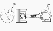
Piston Ring Gap
Insert the piston ring into the lower part of the cylinder (the least
worn out part) with a piston ring compressor and piston. Measure the
ring gap with a feeler gauge. If the measurement exceeds the allowable
limit, replace the piston ring. Top ring - 0.20 to 0.35 mm / 0.0079 to
0.0138 in. Second ring - 0.35 to 0.50 mm / 0.0138 to 0.0197 in. Oil ring
- 0.20 to 0.35 mm / 0.0079 to 0.0138 in.
Clearance between Piston Ring and Piston Ring
Groove
Clean the rings and the ring grooves, and install each ring in its
groove. Measure the clearance between the ring and the groove with a
feeler gauge. If the clearance exceeds the allowable limit, replace the
piston ring. If the clearance still exceeds the allowable limit after
replacing the ring, replace the piston. Second ring - 0.090 to 0.120 mm
/ 0.00354 to 0.00472 in. Oil ring - 0.04 to 0.08 mm / 0.0016 to 0.0031
in.
Kubota BX2350, BX2370, BX2380 - Crankshaft
Crankshaft Side Clearance
Set a dial indicator with its tip on the end of the crankshaft. Measure
the side clearance by moving the crankshaft to the front and rear. If
the measurement exceeds the allowable limit, replace the thrust
bearings. If the same size bearing is useless because of the crankshaft
journal wear, replace it with an oversize one. Crankshaft side clearance
- 0.15 to 0.31 mm / 0.0059 to 0.0122 in.
Crankshaft Alignment
Support the crankshaft with V blocks on the surface plate at both end
journals. Set a dial indicator with its tip on the intermediate journal.
Measure the crankshaft alignment. If the measurement exceeds the
allowable limit, replace the crankshaft. Crankshaft alignment -
Allowable limit 0.02 mm / 0.0008 in.
Oil Clearance between Crankpin and Crankpin
Bearing
Clean the crankpin and crankpin bearing. Put a strip of plastigage on
the center of the crankpin. Install the connecting rod cap and tighten
the connecting rod screws to the specified torque, and remove the cap
again. Measure the amount of the flattening with the scale, and get the
oil clearance. If the oil clearance exceeds the allowable limit, replace
the crankpin bearing. If the same size bearing is useless because of the
crankpin wear, replace it with an undersize one referring to the table
and figure. Be sure not to move the crankshaft while the connecting rod
screws are tightened. Oil clearance between crankpin and crankpin
bearing - 0.020 to 0.051mm / 0.00079 to 0.00201 in. Crankpin O.D. -
33.959 to 33.975 mm / 1.33697 to 1.33760 in. Crankpin bearing I.D. -
33.995 to 34.010 mm / 1.33839 to 1.33898 in.
Oil Clearance between Crankshaft Journal and
Crankshaft Bearing 1
Measure the O.D. of the crankshaft front journal with an outside
micrometer. Measure the I.D. of the crankshaft bearing 1 with an inside
micrometer, and calculate the oil clearance. If the oil clearance
exceeds the allowable limit, replace the crankshaft bearing 1. Oil
Clearance between crankshaft journal and crankshaft bearing 1 - 0.034 to
0.106 mm / 0.00134 to 0.00417 in.
Oil Clearance between Crankshaft Journal and
Crankshaft Bearing 2 and Crankshaft Bearing 3
Put a strip of plastigage on the center of the journal. Install the
bearing case and tighten the bearing case screws 1 to the specified
torque, and remove the bearing case again. Measure the amount of the
flattening with the scale, and get the oil clearance. If the oil
clearance exceeds the allowable limit, replace the crankshaft bearing 2
(crankshaft bearing 3). Oil clearance between crankshaft journal and
crankshaft bearing 2 (crankshaft bearing 3) - 0.028 to 0.059 mm /
0.00110 to 0.00232 in. Crankshaft journal O.D. (Flywheel side) - 43.934
to 43.950 mm / 1.72968 to 1.73031 in. Crankshaft bearing 2 I.D. - 43.978
to 43.993 mm / 1.73142 to 1.73201 in.
________________________________________________________________________________
________________________________________________________________________________________
 SPECIFICATIONS
 LOADERS
 ENGINES
 INSTRUCTIONS
 PROBLEMS
________________________________________________________________________________________
 B2320
B2320 B2630
B2630 B2920
B2920 B3300SU
 BX2360
________________________________________________________________________________________
 L245
L245 L260
L260 L275
L275 L285
L285 L305
L305________________________________________________________________________________________
________________________________________________________________________________________
 D662
D662 D722
D722 D750
D750 D782
D782 D850
D850________________________________________________________________________________________
 LA302
LA302 LA304
LA304 LA340
LA340 LA344
LA344 LA351
LA351________________________________________________________________________________________
 BX2660
 L2501
L2501 L3240
L3240 L3540
L3540 L3940
L3940________________________________________________________________________________________
 D902
D902 D905
D905 D950
D950 D1005
D1005 D1100
D1100________________________________________________________________________________________
________________________________________________________________________________________
 B1630
B1630 BF400
BF400 BF400G
 LA181
LA181 LA203
LA203________________________________________________________________________________________
 LA211
LA211 LA243
LA243 LA271
LA271 LA272
LA272 LA301
LA301________________________________________________________________________________________
 L175
L175 L185
L185 L210
L210 L225
L225 L235
L235________________________________________________________________________________________
 D1105
D1105 D1503
D1503 D1703
D1703 D1803
D1803 V1200
V1200________________________________________________________________________________________
 L4400
L4400 L4600
L4600 L5040
L5040 L5740
L5740 MX4700
________________________________________________________________________________________
 LA352
LA352 LA364
LA364 LA401
LA401 LA402
LA402 LA403
LA403________________________________________________________________________________________
 LA434
LA434 LA463
LA463 LA481
LA481 LA482
LA482 LA504
LA504________________________________________________________________________________________
 V1205
V1205 V1305
V1305 V1505
V1505 V2203
V2203 V2403
V2403________________________________________________________________________________________
 B2710
B2710 BX23S
BX23S B3350
B3350 BX1880
 L4701
L4701________________________________________________________________________________________
 LA513
LA513 LA514
LA514 LA524
LA524 LA525
LA525 LA534
LA534________________________________________________________________________________________
 LA555
LA555 LA680
LA680 LA681
LA681 LA682
LA682 LA703
LA703________________________________________________________________________________________
 Z482
Z482 Z602
Z602 Z750
Z750 Z1100
Z1100 Z1300
Z1300________________________________________________________________________________________
 M100GX
 M135GX
 M6040
M6040 M8540
M8540 M95X
M95X________________________________________________________________________________________
 LA714
LA714 LA723
LA723 LA724
LA724 LA764
LA764 LA765
LA765________________________________________________________________________________________
 LA805
LA805 LA844
LA844 LA852
LA852 LA853
LA853 LA854
LA854________________________________________________________________________________________
 M5-091
 BX2680
 MX5200
 BX2380
 L3901
L3901________________________________________________________________________________________
 LA1002
 LA1055
 LA1065
 LA1153
 LA1154
________________________________________________________________________________________
 LA1251
 LA1301S
 LA1353
 LA1403
 LA1601S
________________________________________________________________________________________
 LA1854
 LA1944
 LA1953
 LA2253
 LM2605