________________________________________________________________________________
Kubota BX23, BX23S - BT603 Backhoe
Kubota BX23, BX23S Hydraulic System
Checking relief valve
Checking relief valve setting pressure - The relief valve of Kubota
BX23, BX23S tractor hydraulic system is used as a relief valve of the
backhoe hydraulic system. Check the relief valve pressure - The pressure
should be within the specification shown. Relief valve pressure 12.3 to
12.7 MPa / 1778 to 1849 psi. Checking control lever operation force - If
measurement is not within the factory specification, adjust by
tightening bolt and nut. Control lever operating force - 10 to 15 N /
2.3 to 3.3 lbf. Checking stabilizer control lever operation force -
Check the stabilizer control lever operating force. If measurement is
not within the factory specification, adjust by tightening bolt and nut.
Stabilizer control lever operating force - 20 to 25 N / 4.5 to 5.6 lbf.
Hydraulic hoses
Disconnecting hydraulic hoses - Slowly release all hydraulic pressure by moving the hydraulic control levers of the backhoe in all directions. Disconnect the hydraulic hoses in the following manner. Disconnect the inlet hose, the outlet hose, and the power beyond hose from the tractor. Connect the outlet hose of the tractor to the coupler of the power beyond pipe. Cap the couplers on the backhoe. Connecting hydraulic hoses - Connect the inlet hose, outlet hose, and the power beyond hose of the backhoe to the outlet hose, the power beyond pipe and the return pipe of Kubota BX23, BX23S tractor.
Removing stabilizers and stabilizer cylinder
Remove the pins and remove the stabilizer cylinder with hydraulic hoses. Remove the pin and remove the stabilizer. Lock the locking nuts to setting bolts at position where the setting bolt may still be rotated. Removing lever support and control valve - Remove the valve covers. Disconnect the control lever rods of valve side. Remove the lever support with control levers. Disconnect the hydraulic hoses. Remove the control valve.
Disassembling control valve
Remove the
spring and load check valve. Remove the seal plate from valve housing.
Remove the cap and draw out the spool from the valve housing. Clean all
parts with a suitable solvent, and dry with a lint-free cloth or air.
Visually inspect all parts for signs of scoring or damage. Install the
spool and seal plate to the valve housing, being careful not to damage
the O-rings.
Kubota BT603 Backhoe hydraulic cylinders
Disassembling cylinder (Boom, dipperstick, bucket, swing, stabilizer)
Drain hydraulic oil from the cylinder, and secure the tube end of the
cylinder in a vise. Remove the cylinder head with the adjustable gland
nut wrench. Pull out the piston rod assembly from the cylinder tube.
Visually inspect the cylinder tube for signs of scoring or damage.
Insert the piston rod assembly to the cylinder tube, being careful not
to damage the piston seal on the piston. Install the cylinder head to
the cylinder tube, being careful not to damage the O-ring on the
cylinder head. Boom cylinder head - 350 to 400 Nm / 259 to 295 lbf-ft.
Dipperstick cylinder, stabilizer cylinder head - 250 to 280 Nm / 185 to
206 lbf-ft. Bucket cylinder head - 200 to 230 Nm / 148 to 169 lbf-ft.
Swing cylinder head - 300 to 350 Nm / 222 to 258 lbf-ft. Removing
cylinder head, piston, and nut. Secure the rod end in a vise. Remove the
nut, the piston and cylinder head from the piston rod. Visually inspect
all parts for signs of scoring or damage. Insert the piston rod to the
cylinder head, being careful not to damage the wiper seal and oil seal.
Boom cylinder, swing cylinder piston mounting nut - 250 to 300 Nm / 185
to 221 lbf-ft. Dipperstick cylinder, bucket cylinder, stabilizer
cylinder, piston mounting nut - 150 to 180 Nm / 111 to 132 lbf-ft.
Disassembling Kubota BT603 backhoe
Remove the bucket from the dipper stick. Removing dipperstick and bucket cylinder. Remove the pins and remove the bucket link and guide link. Disconnect the hydraulic hoses and remove the bucket cylinder. Remove the pins and remove the dipperstick. To prevent from the damage of hydraulic hoses, set the wooden block etc. between dipperstick cylinder and boom. Lock the locking nuts to setting bolts at position where the setting bolt may still be rotated. Replace the spacers at their original position. Removing dipperstick cylinder, boom, boom cylinder, and hoses. Disconnect the hydraulic hoses and remove the dipperstick cylinder. Remove the pins and remove the boom cylinder.
Remove the pin and remove the boom. Remove the hydraulic hoses from the control valve. Hoses should not touch the swing frame. Hoses should not be twisted. Lock the locking nuts to setting bolts at position where the mounting bolt may still be rotated. Connect the hydraulic hoses at their original positions and be sure to connect the hose angle as indicated table below. Disconnect the swing cylinder rods from swing frame. Remove the swing frame from main frame. Lock the locking nuts to setting bolts at position where the setting bolt may still be rotated. Reinstall the thrust washers at their original positions. Remove the swing cylinder bottom pin. Disconnect the hydraulic hoses. Remove the swing cylinder.
Kubota BX23, BX23S - Removing BT603 backhoe
Removing BT603 backhoe main frame - Lift the backhoe main frame and release the mounting pins. Disconnect the three hydraulic hoses from Kubota BX23, BX23S tractor. Separate the main frame from the tractor frame. Removing backhoe - Set the swing lock pin to prevent the pivoting of the boom before removing the backhoe. Stand beside the rear tire, fully close the dipperstick, curl the bucket and lower the boom until the back of bucket contacts the ground. Keep the stabilizer pads at height of the following value. Height of stabilizer pads About 381 mm (15.0 in.). Removing backhoe - Start the engine and drive the tractor and loader slowly away from the backhoe. Stop the engine and remove the key from the tractor. Set the parking brake. The entire 3-point hitch can now be reinstalled on the tractor for use with other rear mount implements. Be sure that there is sufficient ballast in the rear tires and an implement is attached to the 3-point hitch before using the loader with the backhoe removed.
Installing Kubota BT603 backhoeRemove the 3-point hitch and / or drawbar (if equipped). Disconnect the mower if attached in position. Make sure that the swing lock pin is installed. Slowly back the tractor and the loader, centering to the main frame of the backhoe. Stop the tractor keeping at the following distance from the backhoe. Distance between tractor and backhoe - 254 to 304 mm (10.0 to 12.0 in.). Stop the engine and set the parking brake. Setting mounting pins - Pull the mounting levers for left and right mounting pins of the main frame of the backhoe to release mounting pins.
Kubota BX23, BX23S - BT603 backhoe Install
Start the engine. Stand beside the rear tire. Move the boom to fully raising position and raise the BT603 backhoe by operating the stabilizers until the mount bar on the main frame of the backhoe is slightly higher than the support hooks on the main frame of the tractor. If the support hooks are not parallel to the mount bars, adjust them with the stabilizers. Move the tractor backward until the support hooks on the main frame of Kubota BX23, BX23S tractor are just beneath the mount bars on the main frame of the backhoe. Lower the mount bars onto the support hooks by operating the stabilizer and the boom control levers. Lower the boom slowly and interlock the mounting pins with the support hooks.
Continue to slowly lower the boom so that the rear wheels are slightly off the ground. Operate the boom or the stabilizers to maximum lift height, and insert the lock pin of the boom. If the slide bar of the mounting pins is inserted to the upper hole, the mounting pin comes off and the backhoe might come off. Therefore, please make sure to insert the slide bar to the lower hole. Move the tractor, the loader, the backhoe to a vacant area and cycle all backhoe functions. Cycling all backhoe functions will check their operation and flow oil back through the system, filtering it, and refilling each circuit. Check the hydraulic oil level before putting the backhoe into full operation.
Releasing mounting pins
Lower the boom, and raise the rear wheels slightly off the ground. While the mounting levers are pulled, the mounting pins of the main frame may turn in both directions. When the mounting pins come to the release position, push the levers in the holding hole to release the mounting pins. Slowly raise the boom to disengage the backhoe from the tractor. Raise the backhoe by operating the stabilizers to the lowering direction until the mount bars hit to the guide stopper on the support hooks. Move the tractor forward from the backhoe to the following value. Distance between tractor and backhoe - About 203 mm (8.0 in.). Lower the main frame and the swing frame onto the ground by operating the boom and the stabilizer control levers. Stop the engine and set the parking brake.
- Kubota 54/60 inch mower service
- Kubota RCK54, RCK60 mower servicing
- Kubota LA340 Loader for BX23, BX23S tractors
- Kubota LA240 Loader for BX24, BX25, BX25D models
- Kubota BT601 backhoe for BX24, BX25, BX25D tractors
________________________________________________________________________________
________________________________________________________________________________________
________________________________________________________________________________________
________________________________________________________________________________________
________________________________________________________________________________________
________________________________________________________________________________________
________________________________________________________________________________________
________________________________________________________________________________________
________________________________________________________________________________________
________________________________________________________________________________________
________________________________________________________________________________________
________________________________________________________________________________________
________________________________________________________________________________________
________________________________________________________________________________________
________________________________________________________________________________________
________________________________________________________________________________________
________________________________________________________________________________________
________________________________________________________________________________________
________________________________________________________________________________________
________________________________________________________________________________________
________________________________________________________________________________________
________________________________________________________________________________________
________________________________________________________________________________________
________________________________________________________________________________________
________________________________________________________________________________________
________________________________________________________________________________________
________________________________________________________________________________________
________________________________________________________________________________________
________________________________________________________________________________________

 SPECIFICATIONS
 LOADERS
 ENGINES
 INSTRUCTIONS
 PROBLEMS
 B2320
B2320 B2630
B2630 B2920
B2920 B3300SU
 BX2360
 L245
L245 L260
L260 L275
L275 L285
L285 L305
L305 D662
D662 D722
D722 D750
D750 D782
D782 D850
D850 LA302
LA302 LA304
LA304 LA340
LA340 LA344
LA344 LA351
LA351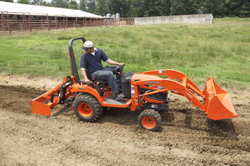 BX2660
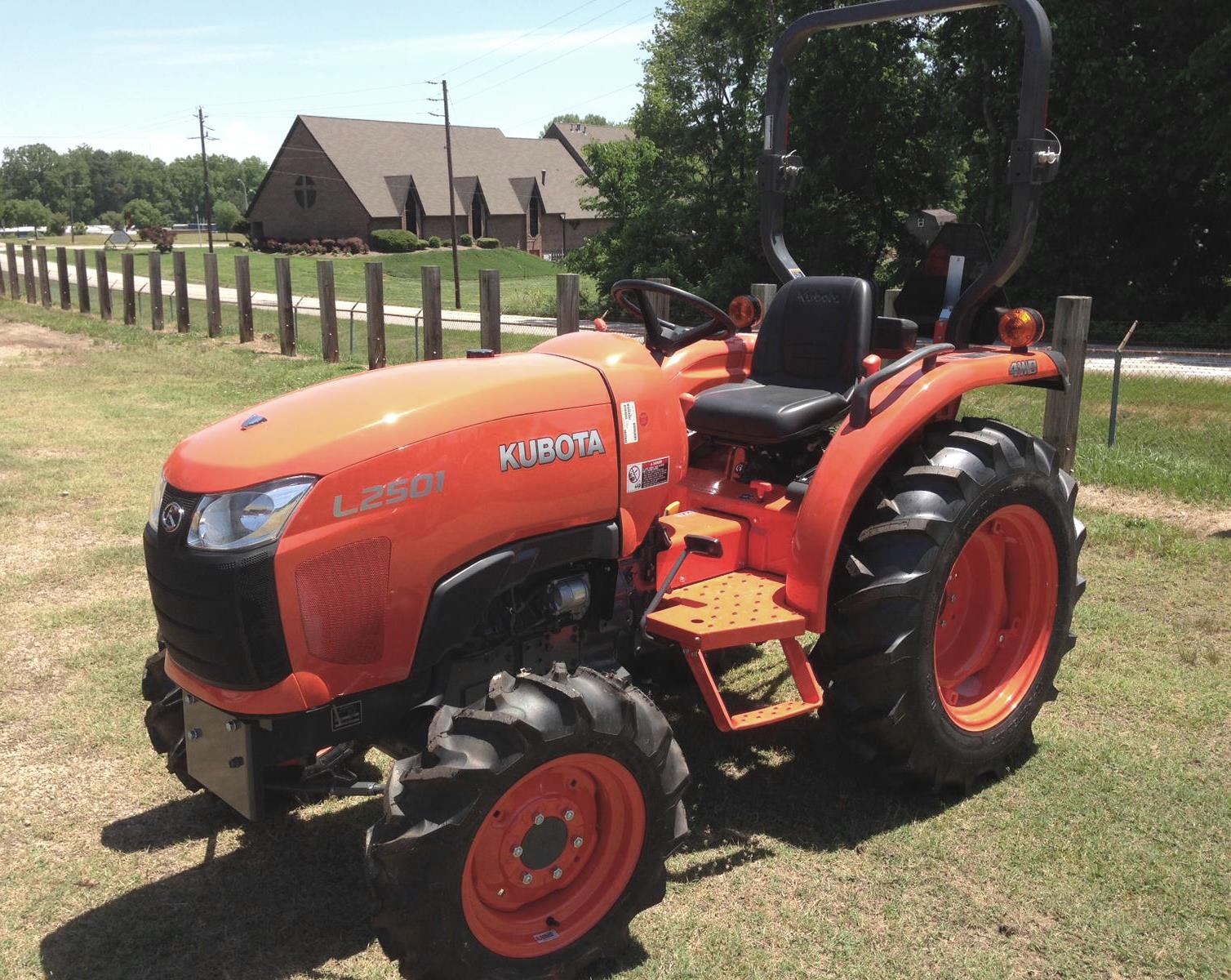 L2501
L2501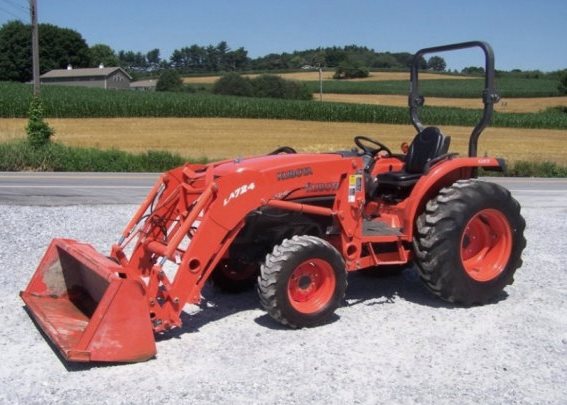 L3240
L3240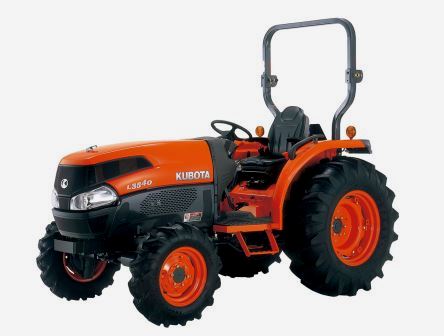 L3540
L3540 L3940
L3940 D902
D902 D905
D905 D950
D950 D1005
D1005 D1100
D1100 B1630
B1630 BF400
BF400 BF400G
 LA181
LA181 LA203
LA203 LA211
LA211 LA243
LA243 LA271
LA271 LA272
LA272 LA301
LA301 L175
L175 L185
L185 L210
L210 L225
L225 L235
L235 D1105
D1105 D1503
D1503 D1703
D1703 D1803
D1803 V1200
V1200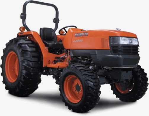 L4400
L4400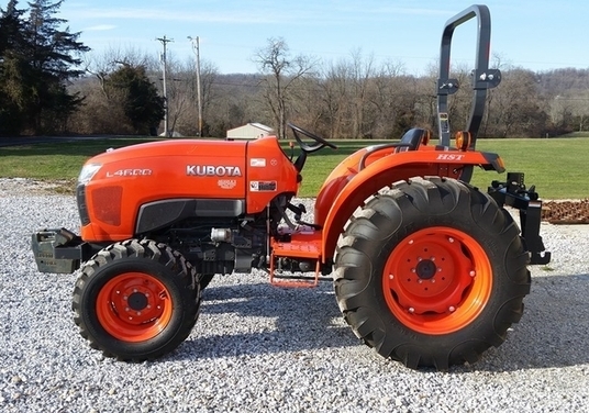 L4600
L4600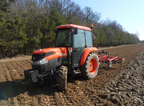 L5040
L5040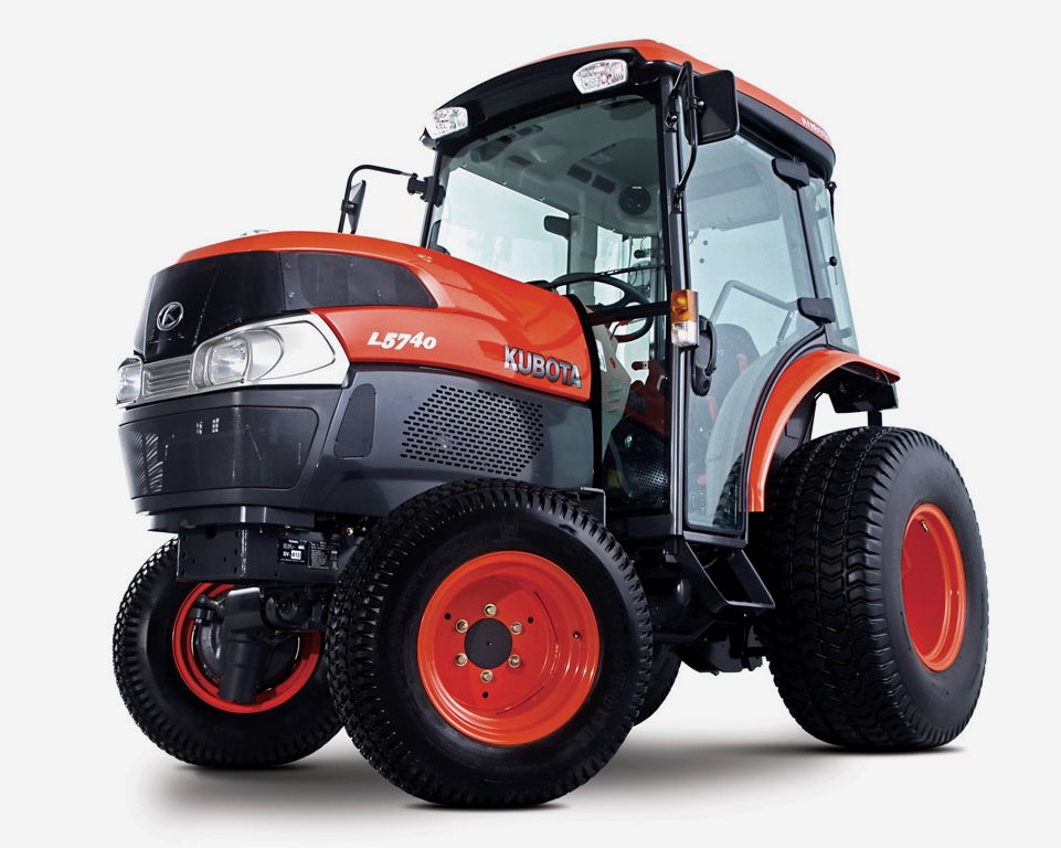 L5740
L5740 MX4700
 LA352
LA352 LA364
LA364 LA401
LA401 LA402
LA402 LA434
LA434 LA463
LA463 LA481
LA481 LA482
LA482 LA504
LA504 V1205
V1205 V1305
V1305 V1505
V1505 V2203
V2203 V2403
V2403 B2710
B2710 BX23S
BX23S B3350
B3350 BX1880
 L4701
L4701 LA513
LA513 LA514
LA514 LA524
LA524 LA525
LA525 LA534
LA534 LA555
LA555 LA680
LA680 LA681
LA681 LA682
LA682 LA703
LA703 Z482
Z482 Z602
Z602 Z750
Z750 Z1100
Z1100 Z1300
Z1300 M100GX
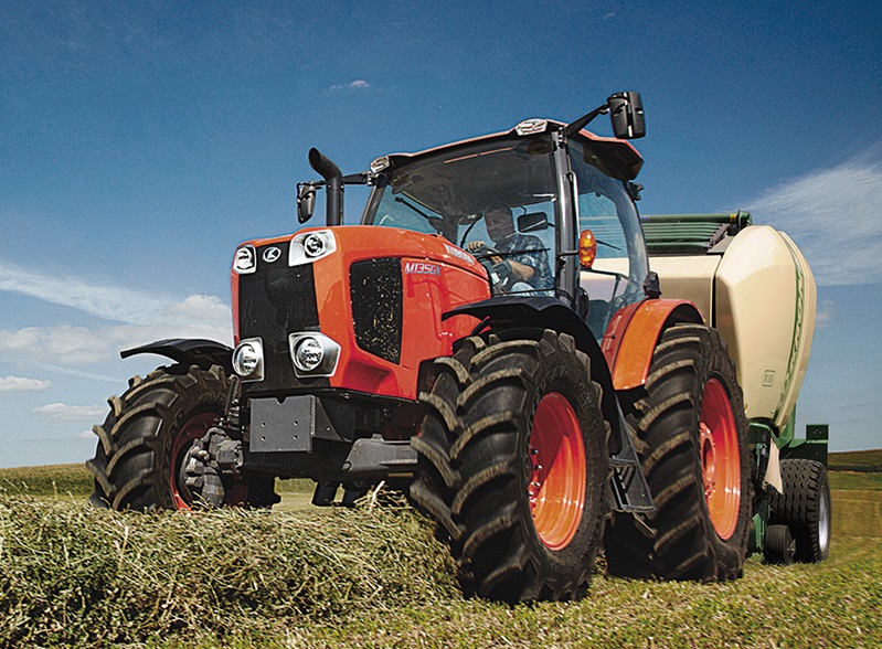 M135GX
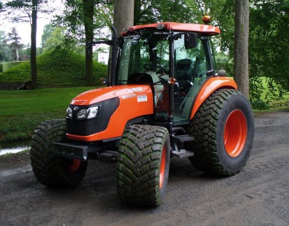 M6040
M6040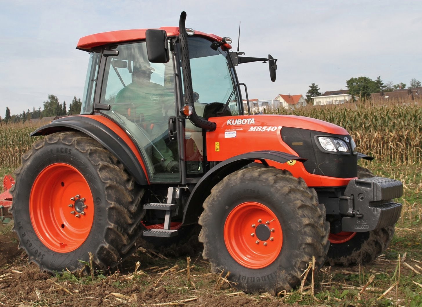 M8540
M8540 M95X
M95X LA714
LA714 LA723
LA723 LA724
LA724 LA764
LA764 LA765
LA765 LA805
LA805 LA844
LA844 LA852
LA852 LA853
LA853 LA854
LA854 M5-091
 BX2680
 MX5200
 BX2380
 L3901
L3901 LA1002
 LA1055
 LA1065
 LA1153
 LA1154
 LA1251
 LA1301S
 LA1353
 LA1403
 LA1601S
 LA1854
 LA1944
 LA1953
 LA2253
 LM2605