________________________________________________________________________________
Kubota BX23, BX23S, BX24, BX25, BX25D Transaxle - Checking and adjusting
Kubota BX23, BX23S, BX24, BX25, BX25D Transaxle - HST adjusting
Adjusting maximum speed
Speed control pedal should contact with adjusting bolt (Forward) and / or (Reverse), when depress the speed control pedal fully. Lift up the rear wheels safely by the rigid jacks. Shift the front wheel drive lever to OFF position. Depress the speed control pedal to the forward all the way and lengthen the stopper bolt (for the forward) until it touches the speed control pedal. Adjust the stopper bolt (for the forward) length and lock it securely. Stopper bolt length Forward 17.0 mm / 0.669 in. Adjust the stopper bolt (for the reverse) length and lock it securely. Stopper bolt length Reverse 17.5 mm / 0.689 in. Finally check the traveling speed or rear axle shaft rotation speed. If the measurement is not within the references, check the adjusting bolt length. Maximum rear axle shaft speed (At engine maximum speed and low range) - 52.2 min-1/52.2 rpm.
Adjusting HST neutral position
Place the wooden blocks at the front and the rear
side of the wheels to prevent tractor from moving. Lift up the rear
wheels and secure with rigid jacks. Remove the R.H. rear wheel from the
Kubota BX23, BX23S, BX24, BX25, BX25D tractor. Shift the front wheel
drive lever to the 4WD off position. Start the engine. Operate the
engine at the maximum revolution. Shift the range shift lever to hi
position. Loosen the locking screw. Depress the speed control pedal to
forward speed position, and release the foot from the speed control
pedal. Check that the rear axle (or the wheel) stops rotating. If the
rear axle (or the wheel) does not stop rotating, move the position of
the locking screw to the machine front side to stop rotating. Depress
the speed control pedal to reverse speed position, and release the foot
from the speed control pedal. Check the rear axle (or the wheel) stops
rotating. If the rear axle (or the wheel) does not stop rotating, adjust
the locking screw to stop rotating. After adjusting the neutral
position, tighten the locking screw securely.
Checking and adjusting HST neutral spring (dynamic braking)
If Kubota BX23, BX23S, BX24, BX25, BX25D tractor moves on level ground with foot off the pedal, or, if the pedal is too slow in returning to neutral position when removing the foot from the pedal, adjust the HST neutral spring. The HST neutral spring located under the front right side of the fender can adjust returning speed of speed control pedal. Since the HST neutral spring tension is weakened, the HST tension should be checked and adjusted every 100 hours.
Checking the HST neutral spring tension
Start the engine and hold the maximum engine speeds. Operate the machine on the concrete level ground. Shift the range gear shift lever to hi position. Depress the speed control pedal to forward. Release the foot from the speed control pedal. Check the distance between the foot releasing point and the machine stopping point. If the distance is more than shown below, strengthen the HST neutral spring tension so that the machine will stop in the specified distance after releasing the foot from the speed control pedal. Distance specification 3 m / 10 ft.
Adjusting the HST neutral spring tension
Remove the step from the
machine. Loosen the lock nut. Turn the adjusting nut half turn to pull
the HST neutral spring. Tighten and lock the lock nut. Start the engine
and check dynamic brake as mentioned former. If the machine will not
stop with dynamic brake in the specified distance, adjust the neutral
spring again. The feeling of dynamic braking can be adjusted by changing
the arm position of damper. Length (M) of adjusting rod at shipping the
machine from the factory specification - 10 mm / 0.39 in.
Kubota BX23, BX23S, BX24, BX25, BX25D Transaxle - Relief valve
Checking charge relief pressure
Remove the plug (R 1/4) from the front cover, then install the adaptor (R 1/4) and pressure gauge. Set the range gear shift lever to neutral position. Start the Kubota BX23, BX23S, BX24, BX25, BX25D engine and operate it at the maximum speed. Read the pressure gauge to measure the charge relief pressure. If the measurement is not within the factory specifications, check the charge relief valve and related hydraulic components. Charge relief pressure 0.55 to 0.75 MPa / 80 to 100 psi. Oil temperature 50C / 122F. When reinstalling the hexagon socket head plug, apply liquid lock (Three Bond 1324 or its equivalent) to the plug. Charge relief valve checking plug (R 1/4) - 30 to 44 Nm / 22 to 32 lbf-ft.
Checking high relief pressure (Forward)
Jack up the machine. Remove the hexagon socket head plug (R 1/4) from P2, then install the adapter, cable, and pressure gauge. Start the engine and operate it at maximum speed. Set the range gear shift lever to hi position. Depress the speed control pedal to forward, and read the pressure gauge to measure the high relief pressure. If the measurement is not the same as factory specification, check the high pressure relief valve and related hydraulic components. High relief pressure (Forward) (Oil temperature at 50C, 122F) - 20.1 to 21.1 MPa / 2920 to 3060 psi.
Checking high relief pressure (Reverse)
Jack up machine. Remove the hexagon socket head plug (R 1/4) from P1,
then install the adapter, cable and, pressure gauge. Start the engine
and operate it at maximum speed. Set the range gear shift lever to hi
position. Depress the speed control pedal to reverse, and read the
pressure gauge to measure the high relief pressure. If the measurement
is not same as factory specification, check the high pressure relief
valve and related hydraulic components. High relief pressure (Reverse)
(Oil temperature at 50C, 122F) - 20.1 to 21.1 MPa / 2920 to 3060 psi.
Hexagon socket head plug (P1 and P2 port) - 30 to 44 Nm / 22 to 32
lbf-ft.
Readjusting relief valve
When HST does not work due to its loose hexagon socket head screw - The relief pressure is set within the factory specification when shipped from the factory. But, for the purpose of after-sales services, as it is impossible to reset the pressure precisely as set in the factory, its setting range is defined as a slightly wider range within the variable specification. Relief pressure - 20.1 to 21.1 MPa / 2920 to 3060 psi. Variable specification - 15.0 to 20.0 MPa / 2180 to 2900 psi. Measure the pre-adjustment distance. Compress the spring of the relief valve with a relief valve assembling tool. Find the distance by turning the poppet with a screwdriver. Distance of relief valve (Forward) Reference value 39.10 to 39.20 mm / 1.540 to 1.543 in. Distance of relief valve (Reverse, D=1.5 mm orifice) 38.60 to 38.70 mm / 1.520 to 1.523 in. The distance changes by about 0.5 mm (0.02 in.) per one turn of the poppet.
Repeat the same operation a few times to find the distance as it is difficult to acquire at the first time. After finding the distance, hold the setscrew to a vice and fasten the hexagon socket head screw with specified torque. On this occasion, use a copper plate, etc. for the vice jaws not to damage the setscrew. Hexagon socket head screw - 25 to 29 Nm / 18 to 21 lbf-ft. Install the relief valve in the HST. Check the relief pressure as indicated in Checking high relief pressure (Forward) and Checking high relief pressure (Reverse). The distance is for refresh only. Make sure to check the relief pressure after readjustment. If the relief pressure does not fall within the readjustment pressure range, repeat the processes of the above. Relief valve readjusting pressure - 15.0 to 20.0 MPa / 2180 to 2900 psi. The pressure changes by 1.5 MPa (15 kgf/cm2, 210 psi) per 0.1 mm (0.004 in.) in distance.
Kubota BX23, BX23S, BX24, BX25, BX25D Transaxle - PTO clutchChecking PTO clutch operating pressure
Lift the rear of the Kubota BX23, BX23S, BX24, BX25, BX25D tractor and remove the left rear wheel. Remove the plug (R 1/8), then install the adapter (R 1/8), cable and pressure gauge. Start the engine and set at maximum speed. Engine speed Oil temperature Maximum 45 to 55C113 to 131F). Move the PTO clutch lever to Engaged position, and measure the pressure. If the measurement is not same as factory specifications, check the PTO relief valve and related hydraulic components. PTO clutch operating pressure - 1.0 to 1.3 MPa / 150 to 180 psi. Tightening torque PTO clutch valve plug (R 1/8) 13 to 21 Nm / 9.4 to 15 lbf-ft.
Adjusting brake pedal free travel
Release the parking brake. Loosen the lock nut and turn the turnbuckle to adjust the rod length. Extend the turnbuckle one additional turn. Retighten the lock nut. Depress the brake pedal several times and make sure the brake pedal free travel is correct according to specification. Brake pedal free travel - 25 to 35 mm / 1.0 to 1.4 in.
- Kubota BX23, BX23S, BX24, BX25, BX25D Transaxle service
- Kubota BX23, BX23S, BX24, BX25, BX25D hydrostatic transmission
- Kubota BX23, BX23S, BX24, BX25, BX25D Front axle
- Kubota BX23, BX23S, BX24, BX25, BX25D Steering
- Kubota BX23, BX23S, BX24, BX25, BX25D hydraulic system
- Kubota BX23, BX23S, BX24, BX25, BX25D electrical system
________________________________________________________________________________
________________________________________________________________________________________
________________________________________________________________________________________
________________________________________________________________________________________
________________________________________________________________________________________
________________________________________________________________________________________
________________________________________________________________________________________
________________________________________________________________________________________
________________________________________________________________________________________
________________________________________________________________________________________
________________________________________________________________________________________
________________________________________________________________________________________
________________________________________________________________________________________
________________________________________________________________________________________
________________________________________________________________________________________
________________________________________________________________________________________
________________________________________________________________________________________
________________________________________________________________________________________
________________________________________________________________________________________
________________________________________________________________________________________
________________________________________________________________________________________
________________________________________________________________________________________
________________________________________________________________________________________
________________________________________________________________________________________
________________________________________________________________________________________
________________________________________________________________________________________
________________________________________________________________________________________
________________________________________________________________________________________
________________________________________________________________________________________

 SPECIFICATIONS
 LOADERS
 ENGINES
 INSTRUCTIONS
 PROBLEMS
 B2320
B2320 B2630
B2630 B2920
B2920 B3300SU
 BX2360
 L245
L245 L260
L260 L275
L275 L285
L285 L305
L305 D662
D662 D722
D722 D750
D750 D782
D782 D850
D850 LA302
LA302 LA304
LA304 LA340
LA340 LA344
LA344 LA351
LA351 BX2660
 L2501
L2501 L3240
L3240 L3540
L3540 L3940
L3940 D902
D902 D905
D905 D950
D950 D1005
D1005 D1100
D1100 B1630
B1630 BF400
BF400 BF400G
 LA181
LA181 LA203
LA203 LA211
LA211 LA243
LA243 LA271
LA271 LA272
LA272 LA301
LA301 L175
L175 L185
L185 L210
L210 L225
L225 L235
L235 D1105
D1105 D1503
D1503 D1703
D1703 D1803
D1803 V1200
V1200 L4400
L4400 L4600
L4600 L5040
L5040 L5740
L5740 MX4700
 LA352
LA352 LA364
LA364 LA401
LA401 LA402
LA402 LA434
LA434 LA463
LA463 LA481
LA481 LA482
LA482 LA504
LA504 V1205
V1205 V1305
V1305 V1505
V1505 V2203
V2203 V2403
V2403 B2710
B2710 BX23S
BX23S B3350
B3350 BX1880
 L4701
L4701 LA513
LA513 LA514
LA514 LA524
LA524 LA525
LA525 LA534
LA534 LA555
LA555 LA680
LA680 LA681
LA681 LA682
LA682 LA703
LA703 Z482
Z482 Z602
Z602 Z750
Z750 Z1100
Z1100 Z1300
Z1300 M100GX
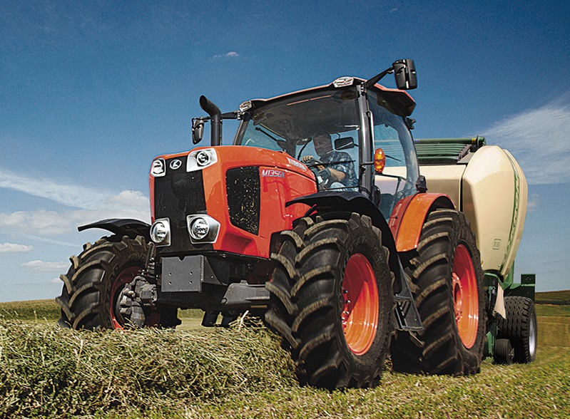 M135GX
 M6040
M6040 M8540
M8540 M95X
M95X LA714
LA714 LA723
LA723 LA724
LA724 LA764
LA764 LA765
LA765 LA805
LA805 LA844
LA844 LA852
LA852 LA853
LA853 LA854
LA854 M5-091
 BX2680
 MX5200
 BX2380
 L3901
L3901 LA1002
 LA1055
 LA1065
 LA1153
 LA1154
 LA1251
 LA1301S
 LA1353
 LA1403
 LA1601S
 LA1854
 LA1944
 LA1953
 LA2253
 LM2605