________________________________________________________________________________
Kubota D902 - Fuel system
Kubota D902 Fuel system - Function and Components
Fuel from the fuel tank passes through the fuel filter, and then enters
the injection pump after impurities such as dirt, water, etc. are
removed. The fuel pressurized by the injection pump to the opening
pressure (13.7 to 14.7 MPa, 140 to 150 kgf/cm2, 1990 to 2133 psi), of
the injection nozzle is injected into the combustion chamber. Part of
the fuel fed to the injection nozzle lubricates the moving parts of the
needle valve inside the nozzle, then returns to the fuel tank through
the fuel overflow pipe from the upper part of the nozzle holder.
Function of fuel filter (Kubota D902 engine for BX2370, BX2380, BX2230,
BX2350, BX2360, BX23, BX23S, BX24, BX25, BX25D tractors) - The fuel
filter filters impurities from the fuel. In-line filter is installed in
the fuel line with an electromagnetic fuel feed pump and is used to
filter impurities such as dirt, water, etc.
Fuel feed pump
An electromagnetic fuel feed pump is used when a fuel
tank is set below the pump of the engine. An electromagnetic fuel feed
pump uses a transistor that causes the pump to start pumping fuel when
the main switch is turned to the ON position. Therefore, fuel is
supplied to the injection pump regardless of engine speed. This pump is
driven by the battery. It can therefore be operated even with the engine
being stopped.
Injection nozzle
Uses as E-TVCS system, the small-sized DENSO made OPD
mini nozzle is of a flat-cut-provided double throttle type. This type of
nozzle is designed to control the injection quantity when the lift rate
is low at start of the injection, and to cut down on the knocking sound
caused by excessive fuel injection by giving the needle valve section
more taper than before to prevent the rapid increase in the injection
quantity when the initial injection turns into the full-force injection.
Also, employed to prevent the injection quantity loss in the throttle
section caused by carbon, the flat cut provided at the needle valve
section helps the throttle withstand long use and reduce as much
knocking sound as when it was new. The heat seal is employed to improve
the durability and reliability of the nozzle.
Kubota D902 Fuel system - Checking and adjusting
Checking injection timing
The liquid gasket is not required for assembling. Shims are available in thickness of 0.20 mm (0.0079 in.), 0.25 mm (0.0098 in.), 0.30 mm (0.012 in.) and 0.175 mm (0.00689 in.). Combine these shims for adjustments. Addition or reduction of shim (0.05 mm, 0.002 in.) delays or advances the injection timing by approx. 0.009 rad (0.5 deg). In disassembling and replacing the injection pump, be sure to use the same number of new shims with the same thickness. The 0.175 mm thick shim is coated only on the lower face. Therefore, do not use the 0.175 mm thick shim as the top shim of the combination (injection pump side), because this can cause oil leakage.
Remove the injection pipes
Remove the engine stop solenoid. Turn the flywheel counterclockwise (viewed from flywheel side) until the fuel fills up to the hole of the delivery valve holder for No. 1 cylinder. After the fuel fills up to the hole of the delivery valve holder for No. 1 cylinder, turn back (clockwise) the flywheel around 1.6 rad (90 deg). Turn the flywheel counterclockwise to set at around 0.44 rad (25 deg) before T.D.C. Slowly turn the flywheel counterclockwise and stop turning when the fuel begins to come up, to get the present injection timing. Check to see the degree on flywheel. The flywheel has mark “1TC”, “10” and “20” for the crank angle before the top dead center of No. 1 cylinder. If injection timing is out of adjustment, readjust the timing with shims. Injection timing (Kubota D902 engine for BX2370, BX2380, BX2230, BX2350, BX2360, BX23, BX23S, BX24, BX25, BX25D tractors) - 0.3360 to 0.3621 rad (19.25 to 20.75 deg) before T.D.C.
Checking fuel tightness of pump element
Remove the engine stop solenoid. Remove the
injection pipes and glow plugs. Install the injection pump pressure
tester to the injection pump. Install the injection nozzle jetted with
the proper injection pressure to the injection pump pressure tester. Set
the speed control lever to the maximum speed position. Run the starter
to increase the pressure. If the pressure cannot reach the allowable
limit, replace the pump with new one. Fuel tightness of pump element
Allowable limit - 13.73 MPa / 1991 psi.
Checking fuel tightness of delivery valve
Remove the engine stop solenoid. Remove the injection pipes and glow plugs. Set a pressure tester to the fuel injection pump. Install the injection nozzle jetted with the proper injection pressure to the injection pump pressure tester. Run the starter to increase the pressure. Stop the starter when the fuel jets from the injection nozzle. After that, turn the flywheel by the hand and raise the pressure. Now turn the flywheel back about half a turn (to keep the plunger free). Keep the flywheel at this position and clock the time taken for the pressure to drop. Measure the time needed to decrease the pressure. If the measurement is less than allowable limit, replace the pump with new one. Fuel tightness of delivery valve 10 seconds - 13.73-12.75 MPa / 1991-1849 psi. Checking nozzle spraying condition - Set the injection nozzle to a nozzle tester, and check the nozzle spraying condition. If the spraying condition is damaged, replace the nozzle piece.
Checking fuel injection pressure
Pressure variation difference of adjusting washer thickness. Set the injection nozzle to a nozzle tester. Slowly move the tester handle to measure the pressure at which fuel begins jetting out from the nozzle. If the measurement is not within the factory specifications, replace the adjusting washer in the nozzle holder to adjust it. Fuel injection pressure (Kubota D902 engine for BX2370, BX2380, BX2230, BX2350, BX2360, BX23, BX23S, BX24, BX25, BX25D tractors) - 13.73 to 14.70 MPa / 1992 to 2133 psi.
Checking valve seat tightness
Set the injection nozzle to a nozzle tester. Raise the fuel pressure, and keep at specified pressure for 10 seconds. Valve seat tightness (No fuel leak at) - 12.75 MPa / 1849 psi. If any fuel leak is found, replace the nozzle piece.
Checking nozzle holder
Secure the nozzle retaining nut with a vise. Remove the nozzle holder, and remove parts inside. Assemble the nozzle in clean fuel oil. Install the push rod, noting its direction. After assembling the nozzle, be sure to adjust the fuel injection pressure. Tightening torque: Nozzle holder - 35 to 39 Nm / 26 to 28 lbf-ft, Overflow pipe retaining nut - 20 to 24 Nm / 15 to 18 lbf-ft, Nozzle holder assembly - 49 to 68 Nm / 37 to 50 lbf-ft.
Kubota D902 Fuel system - Removing and InstallationRemoving injection pump
Disconnect the start spring on the thrust lever side. Align the control rack pin with the notch on the crankcase, and remove the injection pump. Remove the injection pump shims. In principle, the injection pump should not be disassembled. Addition or reduction of shim delays or advances the injection timing. In disassembling and replacing, be sure to use the same number or new gasket shims with the same thickness. When installing the injection pump, insert the control rack pin firmly into the groove of the thrust lever of fork lever.
Removing injection pipes
Loosen the screws to the pipe clamp. Remove the injection pipes. Send compressed air into the pipes to blow out dust. Then, reassemble the pipes in the reverse order. Injection pipe retaining nut - 25 to 34 Nm / 18 to 25 lbf-ft.
Removing nozzle holder assembly and glow plug
Remove the overflow pipe. Remove the nozzle holder assemblies. Remove the copper gasket and heat seal. Remove the lead from the glow plugs. Remove the glow plugs. Replace the copper gasket and heat seal with new ones. Overflow pipe retaining nut - 20 to 24 Nm / 15 to 18 lbf-ft. Nozzle holder assembly - 49 to 68 Nm / 37 to 50 lbf-ft. Glow plug - 7.9 to 14 Nm / 5.8 to 10 lbf-ft.
Removing nozzle heat seal
Use a plus (phillips head) screw driver that has a diameter which is bigger than the heat seal hole. Drive screw driver lightly into the heat seal hole. Turn screw driver three or four times each way. While turning the screw driver, slowly pull the heat seal out together with the injection nozzle gasket. If the heat seal drops, repeat the above procedure. Heat seal and injection nozzle gasket must be changed when the injection nozzle is removed for cleaning or for service. Disconnecting fuel hoses - Disconnect fuel return hose and fuel supply hose from engine. Disconnect fuel filter from engine.
- Kubota D902 Engine body disassembling and assembling
- Kubota D902 Engine body adjusting and servicing
- Kubota D902 Engine cooling system
- Kubota D902 Engine lubricating system
________________________________________________________________________________
________________________________________________________________________________________
________________________________________________________________________________________
________________________________________________________________________________________
________________________________________________________________________________________
________________________________________________________________________________________
________________________________________________________________________________________
________________________________________________________________________________________
________________________________________________________________________________________
________________________________________________________________________________________
________________________________________________________________________________________
________________________________________________________________________________________
________________________________________________________________________________________
________________________________________________________________________________________
________________________________________________________________________________________
________________________________________________________________________________________
________________________________________________________________________________________
________________________________________________________________________________________
________________________________________________________________________________________
________________________________________________________________________________________
________________________________________________________________________________________
________________________________________________________________________________________
________________________________________________________________________________________
________________________________________________________________________________________
________________________________________________________________________________________
________________________________________________________________________________________
________________________________________________________________________________________
________________________________________________________________________________________
________________________________________________________________________________________

 SPECIFICATIONS
 LOADERS
 ENGINES
 INSTRUCTIONS
 PROBLEMS
 B2320
B2320 B2630
B2630 B2920
B2920 B3300SU
 BX2360
 L245
L245 L260
L260 L275
L275 L285
L285 L305
L305 D662
D662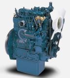 D722
D722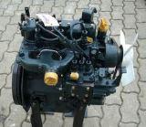 D750
D750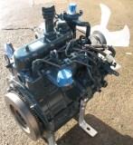 D782
D782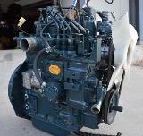 D850
D850 LA302
LA302 LA304
LA304 LA340
LA340 LA344
LA344 LA351
LA351 BX2660
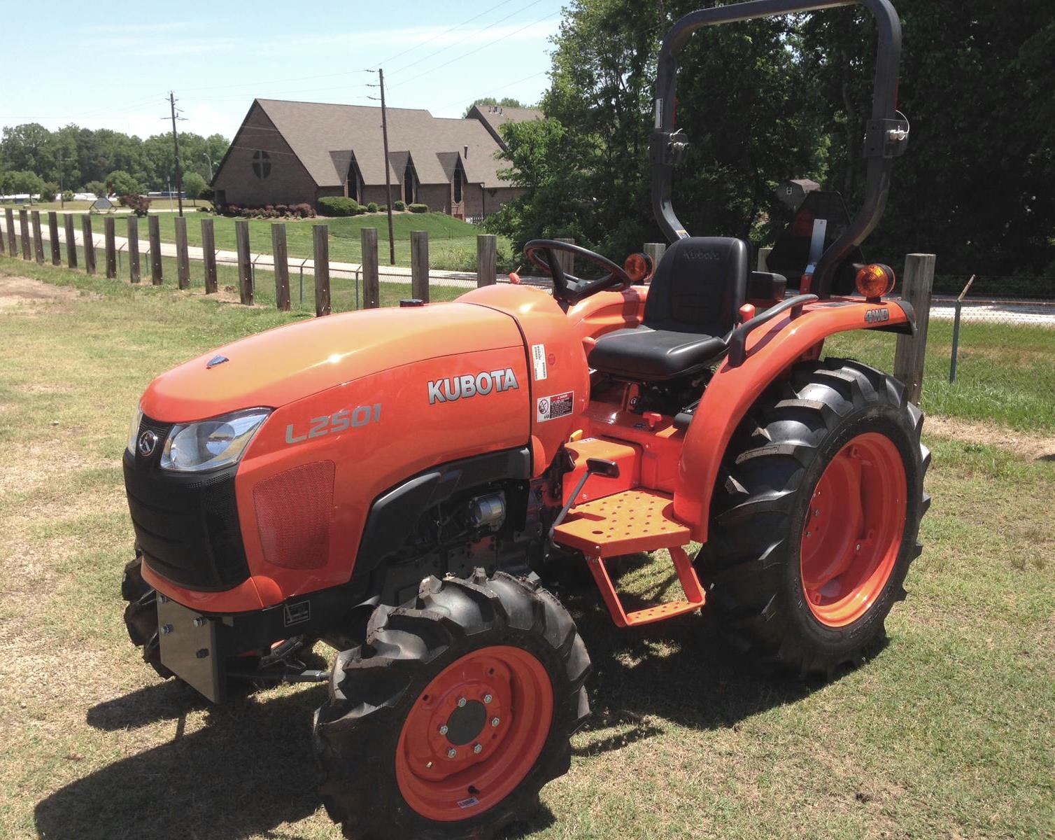 L2501
L2501 L3240
L3240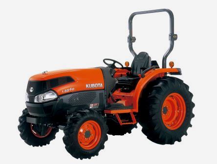 L3540
L3540 L3940
L3940 D902
D902 D905
D905 D950
D950 D1005
D1005 D1100
D1100 B1630
B1630 BF400
BF400 BF400G
 LA181
LA181 LA203
LA203 LA211
LA211 LA243
LA243 LA271
LA271 LA272
LA272 LA301
LA301 L175
L175 L185
L185 L210
L210 L225
L225 L235
L235 D1105
D1105 D1503
D1503 D1703
D1703 D1803
D1803 V1200
V1200 L4400
L4400 L4600
L4600 L5040
L5040 L5740
L5740 MX4700
 LA352
LA352 LA364
LA364 LA401
LA401 LA402
LA402 LA434
LA434 LA463
LA463 LA481
LA481 LA482
LA482 LA504
LA504 V1205
V1205 V1305
V1305 V1505
V1505 V2203
V2203 V2403
V2403 B2710
B2710 BX23S
BX23S B3350
B3350 BX1880
 L4701
L4701 LA513
LA513 LA514
LA514 LA524
LA524 LA525
LA525 LA534
LA534 LA555
LA555 LA680
LA680 LA681
LA681 LA682
LA682 LA703
LA703 Z482
Z482 Z602
Z602 Z750
Z750 Z1100
Z1100 Z1300
Z1300 M100GX
 M135GX
 M6040
M6040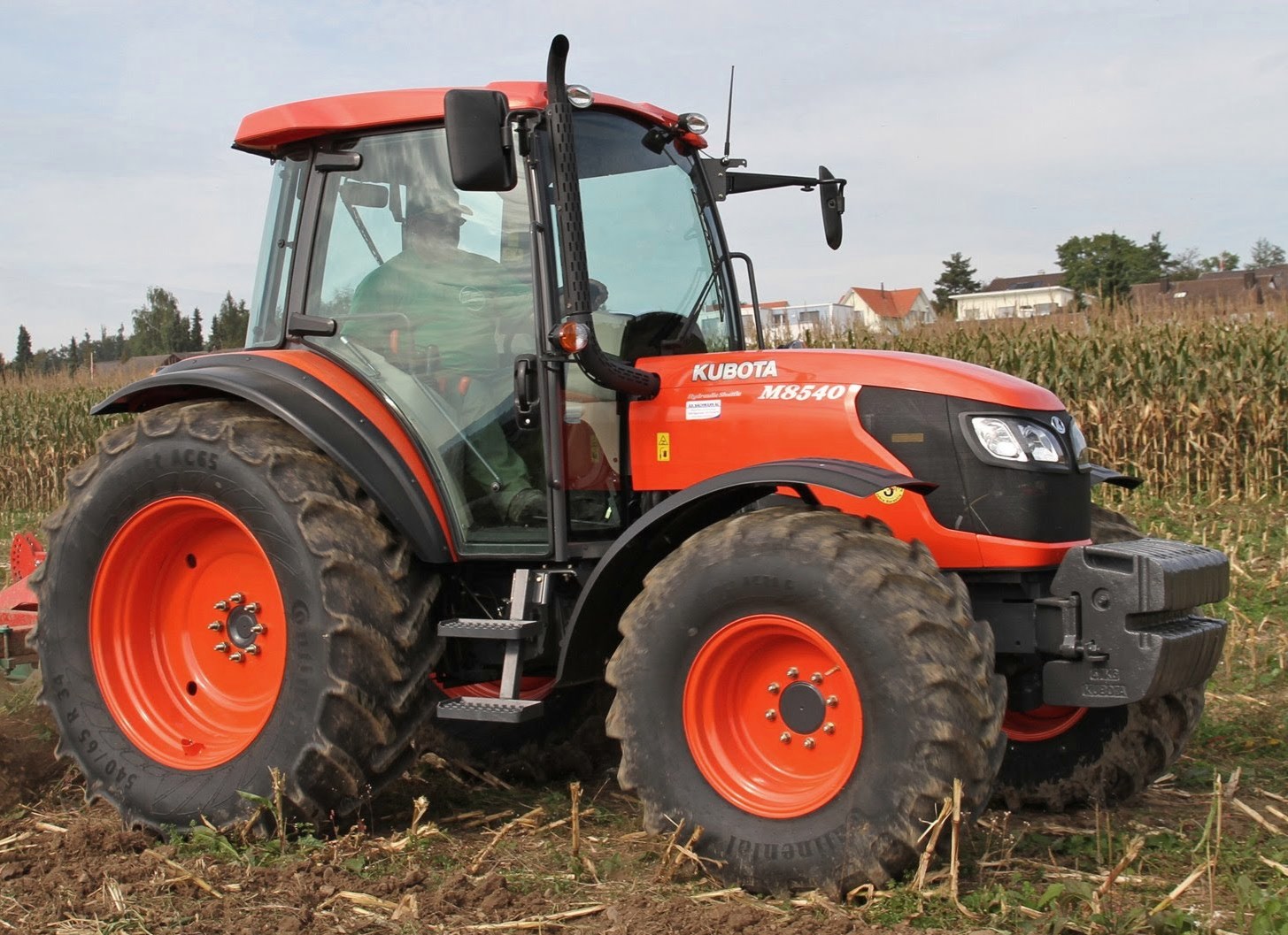 M8540
M8540 M95X
M95X LA714
LA714 LA723
LA723 LA724
LA724 LA764
LA764 LA765
LA765 LA805
LA805 LA844
LA844 LA852
LA852 LA853
LA853 LA854
LA854 M5-091
 BX2680
 MX5200
 BX2380
 L3901
L3901 LA1002
 LA1055
 LA1065
 LA1153
 LA1154
 LA1251
 LA1301S
 LA1353
 LA1403
 LA1601S
 LA1854
 LA1944
 LA1953
 LA2253
 LM2605