
________________________________________________________________________________
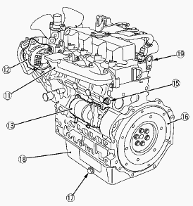
Kubota L2800, L3010, L3130 - Engine Checking and Service
Kubota L3010, L3130 tractors fitted with D1503 diesel engine. D1403
engine used in L2800 model.
Kubota L2800, L3010, L3130 - Engine
Troubleshooting
Engine will not start
Check for an empty fuel tank, incorrect fuel or water in the fuel. Bleed
the fuel system to be sure that fuel is routed to the fuel injection
pump and to locate any restrictions, such as the fuel filter, or
defective components, such as the fuel transfer pump. Check for proper
operation and adjustment of the speed control mechanism, including the
stop lever. Check the fuel injection timing.
Engine speed decreases unexpectedly
Check for water in the fuel. Check for a clogged fuel filter element.
Bleed the fuel system to remove air in the fuel. Check for clogged or
defective fuel injection pump or fuel injector.
Engine will not run under full load
Check for a clogged fuel filter element. Check for a defective fuel
transfer pump. Check for a clogged or defective fuel injection pump.
Check the speed control mechanism.
Engine misfires
Check for water in the fuel. Check for a clogged fuel filter element.
Check for a clogged or defective fuel injection pump or fuel injector.
Kubota D1503 engine Overheating
Loose pump drive belt - A loose drive belt prevents the circulating pump
from operating at the proper speed. Loose hose or pipe connections - Air
may be drawn into the suction side of the system. Worn or defective
water pump - A worn or defective pump may not provide sufficient cooling
water. Dirty cooling system - Debris in the cooling system prevents
adequate heat transfer to the cooling water. Defective or incorrect
thermostat - A defective thermostat may stay closed or not open
sufficiently to allow hot water to leave the engine. An incorrect
thermostat may open at a temperature higher than specified, thereby
raising the temperature of the cooling water in the engine. Conversely,
a thermostat that stays open and doesn’t close or opens at a low
temperature will cause the engine to run at less than optimum
temperature.
Engine Stops Suddenly
This can be caused by engine seizure, a governor malfunction or a
problem in the fuel system. Attempt to start the engine to determine if
the engine rotates freely. Check governor adjustment or to repair the
governor.
Low Oil Pressure
Low engine oil pressure may be caused by leakage in the oil circuit,
excessive bearing clearance, a clogged oil filter, a loose oil regulator
valve or incorrect oil viscosity. Low oil pressure may also be caused by
engine overheating or oil dilution by fuel in the crankcase. Verify low
oil pressure by performing the oil pressure test.
Blue Smoke
Blue exhaust smoke indicates that oil is burning during the combustion
process. Look for a condition that allows oil to enter the combustion
chamber, such as a broken piston, broken or stuck piston rings, a
damaged cylinder wall, worn valves or guides, a defective crankcase
vent, or an overfilled oil sump.
White Smoke
Unburned fuel causes white exhaust smoke. The unburned fuel may be due
to retarded fuel injection timing or insufficient compression pressure.
Low compression pressure may be caused by a damaged cylinder gasket,
broken piston rings, leaking valves or incorrectly adjusted valves. Raw,
unburned fuel may be due to incorrect fuel (low cetane rating) or a
defective injector.
Black Smoke
Black exhaust smoke results from excess fuel (rich) that forms soot when
burned. Either excess fuel or insufficient air can cause black smoke.
Some possible causes are a defective fuel injection pump, poor injector
spray pattern, low injection opening pressure, clogged air intake,
restricted exhaust system or low compression pressure.
Kubota D1503 engine knocks
Check the fuel injection pump timing. Check for a defective fuel
injection pump.
Clicking or Tapping Noises
Clicking or tapping noises usually come from the valve train and
indicate excessive valve clearance. A sticking valve may also sound like
a valve with excessive clearance. In addition, excessive wear in valve
train components can cause similar engine noises.
Knocking Noises
A heavy, dull knocking is usually caused by a worn main bearing. The
noise is loudest when the engine is working hard, such as accelerating
at low speed. It is possible to isolate the trouble to a single bearing
by disabling the fuel injectors on 3-cylinder engines one at a time. By
disabling the fuel injector nearest the bearing, the knock will be
reduced or disappear. Worn connecting rod bearings may also produced a
knock, but the sound is usually more metallic. As with a main bearing,
the noise is worse during acceleration. It may increase in transition
from acceleration to coasting. Disabling the fuel injectors will help
isolate this knock as well. A double knock or clicking usually indicates
a worn piston pin. Disabling fuel injectors will isolate this to a
particular piston; however, the noise will increase when the affected
piston is reached. A loose flywheel and excessive crankshaft end play
also produce knocking noises. While similar to main bearing noises, they
are usually intermittent, not constant, and they do not change when fuel
injectors are disabled. If caused by a loose flywheel or coupling, the
noise is generally heard at idle or during rapid deceleration. Recheck
flywheel/coupler bolt torque whenever accessible. Some mechanics confuse
piston pin noise with piston slap (excessive piston clearance). The
double knock will distinguish piston pin noise. Piston slap will always
be louder when the engine is cold.
Kubota L2800, L3010, L3130 - Engine Checking
Air bleeding the fuel system
Air bleeding of the fuel system is required if: After the fuel filter
and pipes have been detached and refitted; after the fuel tank has
become empty; or before Kubota D1503/D1403 engine is to be used after a
long storage. Fill the fuel tank to the fullest extent. Open the fuel
filter lever. Open the air vent cock on top of the fuel injection pump.
Turn the engine, continue it for about 10 seconds, then stop it, or move
the fuel feed pump lever by hand (optional). Close the air vent cock on
top of the fuel injection pump. Always keep the air vent cock on the
fuel injection pump closed except when air is vented, or it may cause
the engine to stop. For fuel tanks that are lower than the injection
pump. The fuel system must be pressurized by the fuel system electric
fuel pump. If an electric fuel pump is not used, you must manually
actuate the pump by lever to bleed. The primary fuel filter must be on
the pressure side of the pump if the fuel tank is lower than the
injection pump. To bleed, follow through above. Tighten air vent plug of
the fuel injection pump except when bleeding, or it may stop the engine
suddenly.
Checking the fuel pipes
Check the fuel pipes every 50 hours of operation. If the clamp band is
loose, apply oil to the screw of the band, and tighten the band
securely. If the fuel pipes, made of rubber, become worn out, replace
them and clamp bands every 2 years. If the fuel pipes and clamp bands
are found worn or damaged before 2 years pass, replace or repair them at
once. After replacement of the pipes and bands, air-bleed the fuel
system. When the fuel pipes are not installed, plug them at both ends
with clean cloth or paper to prevent dirt from entering. Dirt in the
pipes can cause fuel injection pump malfunction.
Cleaning the fuel filter pot
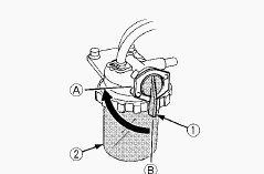
Every 100 hours of operation, clean the fuel filter in a clean place to
prevent dust intrusion. Close the fuel filter lever. Remove the top cap,
and rinse the inside with diesel fuel. Take out the element, and rinse
it with diesel fuel. After cleaning, reinstall the fuel filter, keeping
out of dust and dirt. Air-bleed the injection pump. Entrance of dust and
dirt can cause a malfunction of the fuel injection pump and the
injection nozzle. Wash the fuel filter cup periodically.
Fuel filter cartridge replacement
Replace the fuel filter cartridge with a new one every 400 operating
hours. Apply fuel oil thinly over the gasket and tighten the cartridge
into position by hand-tightening only. Finally, vent the air. Replace
the fuel filter cartridge periodically to prevent wear of the fuel
injection pump plunger or the injection nozzle, due to dirt in the fuel.
Checking oil level and adding engine oil
Check the engine oil level before starting or more than 5 minutes after
stopping the engine. Remove the oil level gauge, wipe it clean and
reinstall it. Take the oil level gauge out again, and check the oil
level. If the oil level is too low, remove the oil filler plug, and add
new oil to the prescribed level. After adding oil, wait more than 5
minutes and check the oil level again. It takes some time for the oil to
drain down to the oil pan. Engine oil capacity - 7.5-9.5 L.
Kubota L2800, L3010, L3130 - Changing engine oil
Change oil after the initial 50 hours of operation and every 200 hours
thereafter. Remove the drain plug at the bottom of the engine, and drain
all the old oil. Drain oil will drain easier when the oil is warm. Add
new engine oil up to the upper limit of the oil level gauge.
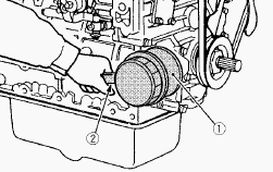
Replacing the oil filter cartridge
Replace the oil filter cartridge. Apply a film of oil to the gasket for
the new cartridge. Screw in the cartridge by hand. When the gasket
contacts the seal surface, tighten the cartridge enough by hand.
Because, if you tighten the cartridge with a wrench, it will be
tightened too much. After the new cartridge has been replaced, the
engine oil level normally decreases a little. Thus, run the engine for a
while and check for oil leaks through the seal before checking the
engine oil level. Add oil if necessary.
Checking coolant level, adding coolant
Remove the radiator cap, after the engine has completely cooled, and
check to see that coolant reaches the supply port. If the radiator is
provided with a recovery tank, check the coolant level of the recovery
tank. When it is between the "Full" and "Low" marks, the coolant will
last for one day's work. When the coolant level drops due to
evaporation, add water only up to the full level. Check to see that two
drain cocks; one is at the crankcase side and the other is at the lower
part of the radiator. If the radiator cap has to be removed, follow the
caution and securely retighten the cap. If coolant should be leak,
repair it or replace. Make sure that muddy or sea water does not enter
the radiator. Use clean, fresh water and 50% anti-freeze to fill the
recovery tank. Do not refill recovery tank with coolant over the "Full"
level mark. Be sure to close the radiator cap securely. If the cap is
loose or improperly closed, coolant may leak out and decrease quickly.
Kubota L2800, L3010, L3130 - Engine Components
Cylinder Head Surface Flatness
Clean the cylinder head surface. Put a straightedge on the cylinder
head. Measure the clearance with a feeler gauge at the 6 places. If the
measurement is more than the allowable limit, make it straight with a
surface grinder. Cylinder head surface flatness - Allowable limit 0.05
mm / 0.002 in.
Cylinder Head Flaw
Prepare an air spray red check. Clean the surface of the cylinder head
with detergent. Apply some red permeative liquid on the cylinder head
surface. After you apply, do not touch it for 5 to 10 minutes. Clean
away the red permeative liquid on the cylinder head surface with
detergent. Apply the white developer on the cylinder head surface. If
you found a red flaw, replace the cylinder head.
Valve Recessing
Clean the cylinder head surface, valve face and valve seat. Set the
valve into the valve guide. Measure the valve recessing with a depth
gauge. If the measurement is more than the allowable limit, replace the
valve. If it stays more than the allowable limit after you replace the
valve, replace the cylinder head. Valve recessing - 0.65 to 0.85 mm /
0.026 to 0.033 in.
Clearance between Valve Stem and Valve Guide
Remove carbon from the valve guide section. Measure the valve stem O.D.
with an external micrometer. Measure the valve guide I.D. with a small
hole gauge, and calculate the clearance. If the clearance is more than
the allowable limit, replace the valves. If the clearance stays more
than the allowable limit, replace the valve guide also. Clearance
between valve stem and valve guide - 0.040 to 0.070 mm / 0.0016 to
0.0027 in. Valve stem O.D. - 7.960 to 7.975 mm / 0.3134 to 0.3139 in.
Valve guide I.D. - 8.015 to 8.030 mm / 0.3156 to 0.3161 in.
Replacement of Valve Guide
Press out the used valve guide with the valve guide replacing tool.
Clean the new valve guide and valve guide bore, and apply engine oil to
them. Press fit the new valve guide with the valve guide replacing tool.
Ream accurately the I.D. of the valve guide to the specified dimension.
Valve guide I.D. (Intake and exhaust) - 8.015 to 8.030 mm / 0.3156 to
0.3161 in.
Correction of valve seat
Slightly correct the seat surface with a 1.0 rad (60°) or 0.79 rad (45°)
valve seat cutter. Correct the seat surface with a 0.52 rad (30°) or
0.26 rad (15°) valve seat cutter. The width must be near the specified
valve seat width (2.12 mm, 0.0835 in.). After you correct the seat,
examine that the valve seating is flat. Apply a thin layer of compound
between the valve face and valve seat, and lap them with a valve lapping
tool. Examine the valve seating with Prussian Blue. The valve seating
surface must show good contact on all sides.
Valve Lapping
Apply the compound equally to the valve lapping surface. Put the valve
into the valve guide. Lap the valve on its seat with a valve lapping
tool. After you lap the valve, clean away the compound and apply oil,
then lap the valve again with oil. Apply Prussian Blue to the contact
surface to measure the seated rate. If the seated rate is less than 70
%, lap the valve again.
Setting Load of Valve Spring
Put the valve spring on a tester. Compress the valve spring to the
specified setting length. Read the compression load on the gauge. If the
measurement is less than the allowable limit, replace the valve spring.
Setting load / Setting length - 118 N / 35.0 mm, 12.0 kgf / 35.0 mm,
26.5 lbf / 1.38 in. Allowable limit - 100 N / 35.0 mm, 10.2 kgf / 35.0
mm, 22.5 lbf / 1.38 in.
Oil Clearance between Rocker Arm and Rocker Arm Shaft
Measure the rocker arm shaft O.D. with an external micrometer. Measure
the rocker arm I.D. with an internal micrometer. Calculate the oil
clearance. If the oil clearance is more than the allowable limit,
replace the rocker arm and measure the oil clearance again. If the oil
clearance stays more than the allowable limit, replace the rocker arm
shaft also. Oil clearance between rocker arm and rocker arm shaft -
0.016 to 0.045 mm / 0.00063 to 0.0017 in. Rocker arm shaft O.D. - 13.973
to 13.984 mm / 0.55012 to 0.55055 in. Rocker arm I.D. - 14.000 to 14.018
mm / 0.55119 to 0.55188 in.
Oil Clearance between Tappet and Tappet Guide Bore
Measure the tappet O.D. with an external micrometer. Measure the tappet
guide bore I.D. with a cylinder gauge. Calculate the oil clearance. If
the oil clearance is more than the allowable limit or the tappet has a
damage, replace the tappet. Oil Clearance between tappet and tappet
guide bore - 0.020 to 0.062 mm / 0.00079 to 0.0024 in. Tappet O.D. -
23.959 to 23.980 mm / 0.94327 to 0.94409 in. Tappet guide bore I.D. -
24.000 to 24.021 mm / 0.94489 to 0.94570 in.
Kubota L2800, L3010, L3130 - Timing Gears
Side Clearance of Idle Gear
Set a dial indicator with its point on the idle gear. Move the idle gear
to the front and rear to measure the side clearance. If the measurement
is more than the allowable limit, replace the idle gear collar. Side
clearance of idle gear - 0.15 to 0.25 mm / 0.0059 to 0.0098 in.
Hold the 2 end journals of camshaft with V blocks on the surface plate.
Set a dial indicator with its point on the middle journal. Turn the
camshaft slowly and read the variation on the indicator. If the
measurement is more than the allowable limit, replace the camshaft.
Kubota D1503/D1403 engine camshaft bend - Allowable limit 0.01 mm /
0.0004 in.
Cam Height
Measure the height of the cam at its highest point with an external
micrometer. If the measurement is less than the allowable limit, replace
the camshaft. Cam height of intake - 33.90 mm / 1.335 in. Cam height of
exhaust - 33.90 mm / 1.335 in.
Oil Clearance of Camshaft Journal
Measure the camshaft journal O.D. with an external micrometer. Measure
the cylinder block bore I.D. for the camshaft with a cylinder gauge.
Calculate the oil clearance. If the oil clearance is more than the
allowable limit, replace the camshaft. Oil clearance of camshaft journal
- 0.050 to 0.091 mm / 0.0020 to 0.0035 in. Camshaft journal O.D. -
39.934 to 39.950 mm / 1.5722 to 1.5728 in. Cylinder block bore I.D. -
40.000 to 40.025 mm / 1.5748 to 1.5757 in.
Oil Clearance between Idle Gear Shaft and Idle Gear Bushing
Measure the idle gear shaft O.D. with an external micrometer. Measure
the idle gear bushing I.D. with an internal micrometer. Calculate the
oil clearance. If the oil clearance is more than the allowable limit,
replace the bushing. If the oil clearance stays more than the allowable
limit, replace the idle gear shaft also. Oil clearance between idle gear
shaft and idle gear bushing - 0.025 to 0.066 mm / 0.00099 to 0.0025 in.
Idle gear shaft O.D. - 37.959 to 37.975 mm / 1.4945 to 1.4950 in. Idle
gear bushing I.D. - 38.000 to 38.025 mm / 1.4961 to 1.4970 in.
Replacement of Idle Gear Bushing
Press out the used idle gear bushing with the replacing tool. Clean a
new idle gear bushing and idle gear bore, and apply engine oil to them.
Press fit the new bushing with the replacing tool. Make sure that the
bushing end aligns the end of the idle gear.
Kubota L2800, L3010, L3130 - Piston and Piston Rings
Piston Pin Bore I.D.
Measure the piston pin bore I.D. in the horizontal and vertical
directions with a cylinder gauge. If the measurement is more than the
allowable limit, replace the piston. Piston pin bore I.D. - 25.000 to
25.013 mm / 0.98426 to 0.98476 in.
Oil Clearance between Piston Pin and Small End Bushing
Measure the piston pin O.D. where it touches the bushing with an
external micrometer. Measure the small end bushing I.D. with an internal
micrometer. Calculate the oil clearance. If the oil clearance is more
than the allowable limit, replace the bushing. If the oil clearance
stays more than the allowable limit, replace the piston pin also. Oil
clearance between piston pin and small end bushing - 0.014 to 0.036 mm /
0.00056 to 0.0014 in. Piston pin O.D. - 25.004 to 25.011 mm / 0.98441 to
0.98468 in. Small end bushing I.D. - 25.025 to 25.040 mm / 0.98524 to
0.98582 in.
Piston Ring Gap
Put the piston ring into the lower part of the liner with the piston.
Measure the ring gap with a feeler gauge. If the ring gap is more than
the allowable limit, replace the ring. Top ring - 0.20 to 0.35 mm /
0.0079 to 0.013 in. Second ring - 0.30 to 0.45 mm / 0.012 to 0.017 in.
Oil ring - 0.20 to 0.40 mm / 0.0079 to 0.015 in.
Clearance between Piston Ring and Groove
Clean the rings and the ring grooves, and install each ring in its
groove. Measure the clearance between the ring and the groove with a
feeler gauge or depth gauge. If the clearance is more than the allowable
limit, replace the piston ring. If the clearance stays more than the
allowable limit with new ring, replace the piston also. Top ring - 0.050
to 0.090 mm / 0.0020 to 0.0035 in. Second ring - 0.0780 to 0.110 mm /
0.00307 to 0.00433 in. Oil ring - 0.030 to 0.070 mm / 0.0012 to 0.0027
in.
Kubota L2800, L3010, L3130 - Crankshaft
Oil Clearance between Crankpin and Crankpin Bearing
Clean the crankpin and crankpin bearing. Put a strip of plastigauge on
the center of the crankpin. Install the connecting rod cap and tighten
the connecting rod screws to the specified torque, and remove the cap
again. Measure the width that it becomes flat with the scale to get the
oil clearance. If the oil clearance is more than the allowable limit,
replace the crankpin bearing. If the same dimension bearing is not
applicable because of the crankpin wear, replace it with an undersize
one. Oil clearance between crankpin and crankpin bearing - 0.025 to
0.087 mm / 0.00099 to 0.0034 in. Crankpin O.D. - 46.959 to 46.975 mm /
1.8488 to 1.8494 in. Crankpin bearing I.D. - 47.000 to 47.046 mm /
1.8504 to 1.8522 in.
Oil Clearance between Crankshaft Journal and Crankshaft Bearing 1
Measure the O.D. of the crankshaft journal with an external micrometer.
Measure the I.D. of the crankshaft bearing 1 with an internal
micrometer. Calculate the oil clearance. If the oil clearance is more
than the allowable limit, replace the crankshaft bearing 1. If the same
dimension bearing is not applicable because of the crankshaft journal
wear, replace it with an undersize one. Oil clearance between crankshaft
journal and crankshaft bearing 1 - 0.0400 to 0.118 mm / 0.00158 to
0.00464 in. Crankshaft journal O.D. - 59.921 to 59.940 mm / 2.3591 to
2.3598 in. Crankshaft bearing 1 I.D. - 59.980 to 60.039 mm / 2.3615 to
2.3637 in.
Replacement of Crankshaft Bearing 1
Press out the used crankshaft bearing 1 with the replacing tool. Clean a
new crankshaft bearing 1 and crankshaft journal bore, and apply engine
oil to them. Make sure that the seam of the new bearing 1 points to the
exhaust manifold side. Then press fit the new bearing 1 with the
replacing tool.
Oil Clearance between Crankshaft Journal and Crankshaft Bearing 2
Put a strip of plastigauge on the center of the journal. Install the
bearing case and tighten the baring case screws 1 to the specified
torque, and remove the bearing case again. Measure the width that it
becomes flat with the scale to get the oil clearance. If the oil
clearance is more than the allowable limit, replace the crankshaft
bearing 2. If the same dimension bearing is not applicable because of
the crankshaft journal wear, replace it with an undersize one. Oil
clearance between crankshaft and crankshaft bearing 2 - 0.0400 to 0.104
mm / 0.00158 to 0.00409 in. Crankshaft journal O.D. - 59.921 to 59.940
mm / 2.3591 to 2.3598 in. Crankshaft bearing 2 I.D. - 59.980 to 60.025
mm / 2.3615 to 2.3631 in.
Replacement of Crankshaft Sleeve
Remove the used crankshaft sleeve. Set the sleeve guide to the
crankshaft. Set the stopper to the crankshaft. Increase the temperature
of a new sleeve to between 150 and 200C (302 and 392F). Install the
sleeve to the crankshaft with the auxiliary socket for pushing. Make
sure that the large chamfer of the sleeve points to outward. If the
temperature of the sleeve is not enough to install, the sleeve can get a
damage when you install.
Replacement of Bearing Case Cover Oil Seal
Remove the used oil seal by using appropriate tool and be careful not to
scratch the bearing case cover. Clean a new oil seal and bearing case
cover. Set the bearing case cover on the replacing tool and fix it with
bolts. Apply a layer of engine oil to the seal outer periphery. Install
the oil seal into the bearing case cover by using the replacing tool,
until it is flash with the bearing case cover.
Kubota L2800, L3010, L3130 - Electrical System Checking
Glow Plug Lead Terminal Voltage
Disconnect the wiring lead from the glow plug after turning the main
switch off. Turn the main switch key to the ON position, and measure the
voltage between the lead terminal and the chassis. Turn the main switch
key to the START position, and measure the voltage between the lead
terminal and the chassis. If the voltage at either position differs from
the battery voltage, the wiring harness or main switch is faulty.
Glow Plug Continuity
Disconnect the lead from the glow plugs. Measure the resistance between
the glow plug terminal and the chassis. If 0 is indicated, the screw at
the tip of the glow plug and the housing are short-circuited. If the
factory specification is not indicated, the glow plug is faulty.
Glow Relay
Connector Voltage - Turn the main switch off. Disconnect the 4P
connector from glow relay. Measure the voltage across the terminal 3
(Positive) and chassis (Negative). If the voltage differs from the
battery voltage, the wiring harness is faulty. Turn the main switch on.
Measure the voltage across the terminal 1 (Positive) and chassis
(Negative). If the voltage differs from the battery voltage, the wiring
harness is faulty. Glow Relay Test - Remove the glow relay. Apply
battery voltage between the terminal 3 and the terminal 4, and check the
continuity of the terminal 1 and the terminal 2. If the continuity is
not established between terminal 1 and the terminal 2, replace the glow
relay.
Engine Stop Solenoid
Disconnect the 2P connector from engine stop solenoid. Turn the main
switch key to the ON position. Measure the voltage between the terminal
1, terminal 2 and body. If the voltage differs from the battery voltage,
the wiring harness or main switch is faulty.
Stop Solenoid Coil
Disconnect the 2P connector from engine stop solenoid. Measure the
resistance between the terminal 1, terminal 2 and body. If the
resistance differs from the factory specification, the coil is faulty.
Engine Stop Solenoid Relay
Connector Voltage - Turn the main switch off. Disconnect the 4P
connector from engine stop solenoid relay. Measure the voltage between
the terminal 3 (Positive) and chassis (Negative). If the voltage differs
from the battery voltage, the wiring harness is faulty. Turn the main
switch on. Measure the voltage between the terminal 1 (Positive) and
chassis (Negative). If the voltage differs from the battery voltage, the
wiring harness is faulty. Engine Stop Solenoid Relay - Remove the engine
stop solenoid relay. Apply battery voltage between the terminal 3 and
the terminal 4, and check the continuity of the terminal 1 and the
terminal 2. If the continuity is not established across terminal 1 and
2, replace the engine stop solenoid relay.
________________________________________________________________________________
________________________________________________________________________________________
 SPECIFICATIONS
 LOADERS
 ENGINES
 INSTRUCTIONS
 PROBLEMS
________________________________________________________________________________________
 B2320
B2320 B2630
B2630 B2920
B2920 B3300SU
 BX2360
________________________________________________________________________________________
 L245
L245 L260
L260 L275
L275 L285
L285 L305
L305________________________________________________________________________________________
________________________________________________________________________________________
 D662
D662 D722
D722 D750
D750 D782
D782 D850
D850________________________________________________________________________________________
 LA302
LA302 LA304
LA304 LA340
LA340 LA344
LA344 LA351
LA351________________________________________________________________________________________
 BX2660
 L2501
L2501 L3240
L3240 L3540
L3540 L3940
L3940________________________________________________________________________________________
 D902
D902 D905
D905 D950
D950 D1005
D1005 D1100
D1100________________________________________________________________________________________
________________________________________________________________________________________
 B1630
B1630 BF400
BF400 BF400G
 LA181
LA181 LA203
LA203________________________________________________________________________________________
 LA211
LA211 LA243
LA243 LA271
LA271 LA272
LA272 LA301
LA301________________________________________________________________________________________
 L175
L175 L185
L185 L210
L210 L225
L225 L235
L235________________________________________________________________________________________
 D1105
D1105 D1503
D1503 D1703
D1703 D1803
D1803 V1200
V1200________________________________________________________________________________________
 L4400
L4400 L4600
L4600 L5040
L5040 L5740
L5740 MX4700
________________________________________________________________________________________
 LA352
LA352 LA364
LA364 LA401
LA401 LA402
LA402 LA403
LA403________________________________________________________________________________________
 LA434
LA434 LA463
LA463 LA481
LA481 LA482
LA482 LA504
LA504________________________________________________________________________________________
 V1205
V1205 V1305
V1305 V1505
V1505 V2203
V2203 V2403
V2403________________________________________________________________________________________
 B2710
B2710 BX23S
BX23S B3350
B3350 BX1880
 L4701
L4701________________________________________________________________________________________
 LA513
LA513 LA514
LA514 LA524
LA524 LA525
LA525 LA534
LA534________________________________________________________________________________________
 LA555
LA555 LA680
LA680 LA681
LA681 LA682
LA682 LA703
LA703________________________________________________________________________________________
 Z482
Z482 Z602
Z602 Z750
Z750 Z1100
Z1100 Z1300
Z1300________________________________________________________________________________________
 M100GX
 M135GX
 M6040
M6040 M8540
M8540 M95X
M95X________________________________________________________________________________________
 LA714
LA714 LA723
LA723 LA724
LA724 LA764
LA764 LA765
LA765________________________________________________________________________________________
 LA805
LA805 LA844
LA844 LA852
LA852 LA853
LA853 LA854
LA854________________________________________________________________________________________
 M5-091
 BX2680
 MX5200
 BX2380
 L3901
L3901________________________________________________________________________________________
 LA1002
 LA1055
 LA1065
 LA1153
 LA1154
________________________________________________________________________________________
 LA1251
 LA1301S
 LA1353
 LA1403
 LA1601S
________________________________________________________________________________________
 LA1854
 LA1944
 LA1953
 LA2253
 LM2605