
________________________________________________________________________________
Kubota L4701, L47, L6060 - Engine Components
Kubota V2403 4-cylinder diesel engine used in L4701, L47, L6060
tractors.
Kubota L4701, L47, L6060 - Fuel System
The common rail system is an electronically controlled fuel injection
device, with a supply pump that pressurizes the fuel, a rail that stores
the high-pressure fuel, injectors that inject the fuel under
high-pressure based on solenoid operation into each cylinder and an
engine ECU that controls all of these components. The injection amount
and injection timing by the injectors and pressure of fuel stored in the
rail are controlled by the engine ECU based on signals from each sensor
and instructions sent by CAN communication from the main ECU on the
tractor. Therefore, fuel is injected under optimal conditions at all
times enabling suppressing of that which is a characteristic of Kubota
V2403 diesel engines, generation of black smoke on start up and under
acceleration achieving reduction in exhaust gas and higher output power.
Separator
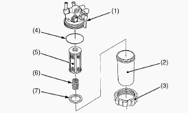
The separator has a function of separating fuel and water through
difference in specific gravity. There is a read float with a specific
weight of 0.9 made of a polypropylene material inside that has
properties in that it is heavier than diesel and lighter than water.
When fuel containing water enters the separator, water with a high
specific weight pools in the bottom of a cup and causes the float to
float. The state of mixing in of water can be recognized by the state of
the float and can be visually inspected externally. Fuel with a low
specific weight flows over the top of the cup but passes through the
element provided inside enabling filth to be removed from the fuel.
SCV
The suction control valve (SCV) is a proportional control valve that
adjusts the amount of fuel delivered from the fuel pump to achieve the
fuel pressure requested by the engine, has a function of delivering to
the pressurizing part, and is made up of a piston, cylinder, armature,
and solenoid etc. The SCV is a linear solenoid type electromagnetic
valve and the engine ECU controls the time the solenoid is electrified
(duty ratio control). When current flows through the solenoid, the
armature moves based on the duty ratio and pushes on the cylinder and
fuel flow changes based on position of the cylinder enabling suitable
fuel flow. Since the suction control valve (SCV) has not been adopted as
a part, replace the supply pump when SCV is needed to replace. Linear
solenoid type: when voltage is applied to the coil, the moveable core
moves linearly in proportion to the voltage based on the magnetic force.
Rail
The rail stores fuel at the high pressure applied by the supply pump and
the injectors of each cylinder. The rail incorporates control parts-a
rail pressure sensor and a pressure limiter. The pressure of the fuel in
the rail is detected by the rail pressure sensor, and optimal feedback
control is provided for the engine RPM and load. This greatly improves
the ability to raise the pressure at low RPMs and enables high-pressure
injection from low speed ranges. The pressure limiter operates when the
pressure inside the rail becomes excessively high (valve opens), and
then once the pressure drops to a certain pressure, it acts to keep the
pressure (valve closes). Fuel discharged by the pressure limiter returns
to the fuel tank.
Rail Pressure Sensor
The rail pressure sensor is mounted on the rail, detects the fuel
pressure inside the rail, converts this to an electronic signal and
sends it to the ECU. The rail pressure sensor is made up of a metal
diaphragm, distortion detection part (metal gauge), signal processing
circuit, and housing etc. When the fuel pressure in the rail is applied
to the metal diaphragm, the diaphragm is distorted. Metal gauges are
positioned in the center and at the edge of the metal diaphragm and
tensile or compression force is applied. A difference in resistance
values is generated based on the force that is applied.
Kubota L4701, L47, L6060 - Injectors
The injectors inject high-pressure fuel sent from the rail into the
combustion chamber of Kubota V2403 engine. The injections are controlled
by the signal of engine's ECU to produce the ideal timing, amount of
fuel, mixture and spray. The injector injects a finely turned spray in
three pulses during the combustion stage. First a small amount is
injected, mitigating the effect of the initial burn and reducing NOx
(oxides of nitrogen) and noise. The main injection follows with the real
burn, and in the last stage, a diffuse combustion is induced, thus
reducing particulate matter (PM) generated by the main injection.
Common Rail and Injection Pipes
Do not remove the pressure limiter and rail pressure sensor from the
common rail. When removing the common rail, do not hold it by the
pressure limiter and rail pressure sensor. Remove the injection pipes.
Remove the overflow pipe. Remove the common rail. Store the injection
pipes so it does not get any dust in it. Store the common rail so it
does not get any dust in it.
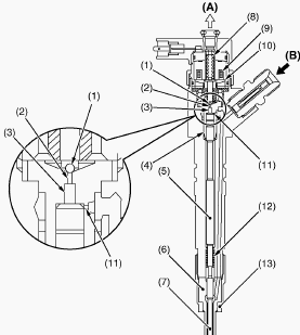
Supply Pump
Remove the intake throttle valve assembly. Remove the EGR valve
assembly. Remove the rail. Remove the intake manifold. Remove the supply
pump. Do not disassemble the supply pump. Store the supply pump so it
does not get any dust in it. When attaching the supply crank case, do
not put force on the MPRP and overflow sections of the part. Do not
remove the dust protection cap until immediately before you attach the
part.
Replacing Fuel Filter
Remove the fuel filter. Put a film of clean fuel on rubber seal of new
filter. Tighten the filter quickly until it contacts the mounting
surface. Tighten filter by hand an additional 1/2 turn only. Bleed the
fuel system.
Cleaning Water Separator
Close the fuel valve. Unscrew the retainer ring and remove the cup, and
rinse the inside with kerosene. Take out the element and dip it in the
kerosene to rinse. After cleaning, reassemble the water separator,
keeping out dust and dirt. Bleed the fuel system.
Checking Fuel Line
Check to see that all line and hose clamp are tight and not damaged. If
hoses and clamps are found worn or damaged, replace or repair them at
once. If the fuel line is removed, be sure to properly bleed the fuel
system.
Kubota L4701, L47, L6060 - Cooling System
Thermostat Assembly
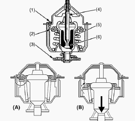
Remove the thermostat cover mounting screws, and remove the thermostat
cover. Remove the thermostat assembly. Replace the thermostat cover
gasket with a new one. Apply a liquid gasket to the water flange 1 and
flange 2.
Water Pump
Remove the water pump assembly from the gear case. Replace the gasket
with a new one. Remove the pipe band and the water pipe (water pump
side). Remove the water pump. When mounting the water pump, be careful
not to forget mounting the O-ring and not to let it out of position.
Checking Coolant Level
Check to see that the coolant level is between the FULL and LOW marks of
recovery tank. When the coolant level drops due to evaporation, add
water only up to the full level. In case of leakage, add anti-freeze and
water in the specified mixing ratio up to the full level. If the
radiator cap has to be removed, follow the caution above and securely
retighten the cap. Use clean, fresh water and anti-freeze to fill the
recovery tank.
Adjusting Fan Belt Tension
Stop Kubota V2403 engine and remove the key. Apply moderate thumb
pressure to belt between pulleys. If tension is incorrect, loosen the
alternator mounting bolts and using a lever placed between the
alternator and the engine block, pull the alternator out until the
deflection of the belt falls within acceptable limits. Replace fan belt
if it is damaged. Fan belt tension - Deflection of between 7 to 9 mm
(0.28 to 0.34 in.) when the belt is pressed in the middle of the span.
Checking Radiator Hose and Hose Clamp
Check to see if radiator hoses are properly fixed every 200 hours of
operation or six months, whichever comes first. If hose clamps are loose
or water leaks, tighten bands securely. Replace hoses and tighten hose
clamps securely, if radiator hoses are swollen, hardened or cracked.
Replace hoses and hose clamps every 2 years or earlier if checked and
found that hoses are swollen, hardened or cracked.
Flushing Cooling System and Changing Coolant
Stop the engine, remove the key and let it cool down. To drain the
coolant, open the radiator drain plug and remove radiator cap. The
radiator cap must be removed to completely drain the coolant. After all
coolant is drained, reinstall the drain plug. Fill with clean soft water
and cooling system cleaner. Follow directions of the cleaner
instruction. After flushing, fill with clean soft water and anti-freeze
until the coolant level is just below the radiator cap. Install the
radiator cap securely. Fill with coolant up to the FULL mark of recovery
tank. Start and operate the engine for few minutes. Stop the engine,
remove the key and let cool. Check coolant level of recovery tank and
add coolant if necessary. Properly dispose of used coolant.
Kubota L4701, L47, L6060 - Engine Control
System
Engine ECU
The engine ECU controls the amount, timing, mixture and pressure of fuel
that is injected. The engine ECU operates each kind of control based on
the signals from each type of sensor. The actuator for controlling the
amount, timing and mixture of fuel injection is the injector, while the
actuator for controlling fuel pressure is the supply pump. Fuel Quantity
Control - The amount of fuel to be injected is determined using a basic
injection amount, which is calculated based on the state of the engine
and driving conditions, with corrections added for parameters such as
water temperature, intake air temperature, intake pressure, etc.
Injection Timing Control - The ECU controls the timing for starting to
energize the injectors, first determining the timing for the main
injection and then setting the timing of other injections, such as pilot
injections. Fuel Mixture Control - By conducting a pilot injection, the
initial fuel mixture is kept to a minimum, mitigating the explosive
initial combustion and reducing NOx and noise. Fuel Pressure Control -
The ECU calculates the set fuel injection pressure based on the engine
load (last injection amount and engine RPM) and controls the amount the
supply pump supplies and the fuel pressure inside the rail.
Sensor
Crankshaft Position Sensor - The crank position sensor is mounted on the
flywheel housing and the sensor body uses a hall element type. When
pulse holes provided on the outer edge of the flywheel pass through the
sensor, the internal magnetic field changes and this is output to the
engine ECU. Also, a no hole part is provided in a part and this detects
the crank position each rotation and outputs this to the engine ECU. The
engine ECU uses the signals to calculate the crank angle and engine
speed.
Camshaft Position Sensor - The cam position sensor is mounted near the
supply pump gear of the gear case and the sensor functions in the same
way as the crank position sensor. This sensor detects the teeth of the
pulsar gear and the engine ECU uses this signal to calculate the cam
angle.
Coolant Sensor - The temperature sensor is mounted to the water flange
and uses a thermistor in the sensor part to detect temperature. A
characteristic of thermistors is that their electrical resistance varies
with temperature, and this characteristic is used by the different
sensors to detect temperature via voltage.
Kubota L4701, L47, L6060 - DPF Regeneration
System
Diesel Particulate Filter (DPF)
The Diesel Particulate Filter (DPF) is a device that captures and
combusts PM in the exhaust gas. Physically captures the PM using a
filter which spontaneously combusts when exhaust gas temperature is
high. However, while exhaust gas temperature is low PM does not
spontaneously combust the pressure differential between the inlet and
outlet of the DPF is detected and the PM is combusted using a heat
source generated using DOC to regenerate the filter. The Diesel
Particulate Filter (DPF) is a filter to capture fine particles (soot and
ash) contained in the exhaust gas of a Kubota V2403 diesel engine. The
ash content is mainly metallic additives contained in burnt lubricating
oil. The filter has a honeycomb structure with adjacent cell holes
alternately closed. In addition, by alternately closing the inlet side
and the outlet side of the exhaust gas, the thin ceramics wall is used
as a filter. Fine particles in the exhaust gas are captured when they
pass through this thin wall, and the exhaust gas is discharged as clean
gas.
Intake Throttle Valve
The amount of air intake is regulated by the angle of the throttle valve
and the exhaust temperature is controlled when regenerating the DPF
muffler.
Air Flow Sensor
The amount of air intake required for control of the EGR valve used to
reduce NOx is measured.
Temperature Sensor
This is mounted on the DPF muffler and the DPF muffler DOC intake, DPF
intake, and DPF discharge exhaust temperature, needed for the post
processing system, are measured.
Kubota L4701, L47, L6060 - Differential
Pressure Sensor
The differential pressure sensor is a sensor that detects the pressure
differential between the inlet and the outlet of the DPF. The engine ECU
calculates the amount of accumulated PM in the DPF using this signal.
Oil Separator
Removes oil in the blow by gases that pass through the element and the
oil is returned to the oil pan. Blow by gases that pass through the
element are mixed into the intake upstream from the turbocharger.
Checking DPF Differential Pressure Sensor
Pipes and Hoses
Be sure to loosen the differential pressure pipe tightening nut with
crowfoot wrench to prevent the damage of the sensor or pipe. If it is
still hard to loosen, apply the lubricant spray to threaded portion and
soak it with lubricant. Tighten bolts and nuts to their specified
torque. Also tighten the differential pressure pipe tightening nut to
the specified torque with crowfoot wrench. Check the DPF differential
pressure sensor pipe for crack, gas leakage and loose mounting nut. If
you find a crack, change the DPF differential pressure sensor pipe. If
you find a gas leakage, remove the DPF differential pressure sensor pipe
and wipe off the anti-seize and lubricating compound. Apply the
anti-seize and lubricating compound again, then tighten the DPF
differential pressure sensor pipe to the specified torque. Check the DPF
differential pressure sensor hose for crack, gas leakage. If you find a
crack or gas leakage, change the DPF differential pressure sensor hose.
Kubota L4701, L47, L6060 - Electrical System
Starter Disassembling
Disassembling Motor - Disconnect the connecting lead from the magnet
switch. Remove the screws, and then separate the end frame, yoke and
armature. Remove the two screws, and then take out the brush holder from
the end frame. Disassembling Magnet Switch - Remove the drive end frame
mounting screws. Take out the overrunning clutch, ball, spring, gear,
rollers and retainer. Apply grease to the gear teeth of the gear and
overrunning clutch, and ball. Plunger - Remove the end cover. Take out
the plunger.
Starter Service
Overrunning Clutch - Inspect the pinion for wear or damage. If there is
any defect, replace the overrunning clutch assembly. Check that the
pinion turns freely and smoothly in the overrunning direction and dose
not slip in the cranking directions. If the pinion slips or dose not
rotate in the both directions, replace the overrunning clutch assembly.
Armature Bearing - Check the bearing for smooth rotation. If it dose not
smooth rotation, replace it. Brush Wear - If the connect face of the
brush is dirty or dusty, clean it with emery paper. Measure the brush
length with vernier caliper. If the length is than the allowable limit,
replace the yoke assembly and brush holder. Brush Holder - Check the
continuity across the brush holder and the holder support with an
ohmmeter. If it conducts, replace the brush holder. Field Coil - Check
the continuity across the lead and brush with an ohmmeter. If it dose
not conduct, replace the yoke assembly. Check the continuity across the
brush and yoke with an ohmmeter. If it conducts, replace the yoke
assembly.
Alternator Disassembling
Secure the hexagonal end of the pulley shaft with a double ended ratchet
wrench, loosen the pulley nut with a socket wrench and remove it.
Unscrew the three rear end cover screws and the B terminal nut, and
remove the rear end cover. Unscrew the two screws holding the brush
holder, and remove the brush holder. Unscrew the three screws holding
the IC regulator, and remove the IC regulator. Remove the four screws
holding the rectifier and the stator lead wires. Remove the rectifier.
Unscrew the two nuts and two screws holding the drive end frame and the
rear end frame. Remove the rear end frame. Press out the rotor from
drive end frame. Unscrew the four screws holding the retainer plate, and
remove the retainer plate. Press out the bearing from drive end frame
with a press and jig. Lightly secure the rotor with a vise to prevent
damage, and remove the bearing with a puller.
Alternator Service
Bearing - Check the bearing for smooth rotation. If it does not rotate
smoothly, replace it. Stator - Check the continuity across each stator
coil lead and core with an ohmmeter. If infinity is not indicated,
replace it. Rotor - Measure the resistance across the slip rings with an
ohmmeter. If the resistance is not the factory specification, replace
it. Check the continuity across the slip ring and core with an ohmmeter.
If infinity is not indicated, replace it. Slip Ring - Check the slip
ring for score. If scored, correct with an emery paper or on a lathe.
Measure the O.D. of slip ring with vernier calipers. If the measurement
is less than the allowable limit, replace it. Slip ring O.D. - Allowable
limit 14.0 mm (0.551 in). Brush Wear - Measure the brush length with
vernier calipers. If the measurement is less than allowable limit,
replace it. Make sure that the brush moves smoothly. If the brush is
defective, replace it. Allowable limit 8.4 mm (0.331 in). Rectifier -
Check the continuity across each diode of rectifier with an analog
ohmmeter. Conduct the test in the (Rx1) setting. The rectifier is normal
if the diode in the rectifier conducts in one direction and does not
conduct in the reverse direction.
Separating DPF Muffler from Kubota L4701, L47,
L6060 tractor
Front Grill, Skirts and Bonnet
Pull down the knob and open the bonnet. Disconnect the battery negative
cable. Remove the front grill, left and right side skirts. Disconnect
the head light connector. Remove the damper. Remove the pin, then the
bonnet. When disconnecting the battery cables, disconnect the negative
cable first. When connecting the battery cables, connect the positive
cable first.
DPF Muffler
Remove the damper support. Disconnect the differential pressure
connector and DPF temperature sensor connectors. Remove the muffler pipe
mounting screws. Remove the DPF mounting screws R.H. Remove the exhaust
flange mounting screws. Remove the DPF mounting screws L.H. Remove the
DPF muffler using hoist. When mounting the DPF muffler to the bracket,
make sure to follow the procedures below. Loosen the bracket mounting
screws between the bracket and the exhaust flange. Loosen the bracket
mounting screws until the bracket can move. Mount the DPF muffler to the
bracket and temporarily tighten the screws. Tighten evenly and properly
the exhaust flange mounting screws. Tighten evenly and properly the
bracket mounting screws between the bracket and the exhaust flange.
Tighten evenly and properly the bracket mounting screws. Tighten evenly
and properly the DPF muffler mounting screws R.H and then the DPF
muffler mounting screws L.H. Tighten evenly and properly the muffler
pipe mounting screws.
Filter Comp (DPF)
Always work in the workshop equipped with a electric hoist (including
mobile hoist). Put a tractor on a stable ground, and set the parking
brake. As the DPF muffler is hot just after the engine shutdown, make
sure to start operation after it gets cool. Make sure not to let any
foreign substances enter the opening section during the operation. Make
sure not to damage the DPF muffler full assembly by falling or impact as
it contains a ceramic filter. Before removing the DPF for cleaning, keep
the records of the engine serial number, DPF muffler full assembly part
number, DPF muffler full assembly serial number, and engine operating
time, which are required in preparing the DPF cleaning order from. Since
the engine operating time is recorded in the ECU, check the operating
time by connecting the service tool. When installing and removing the
muffler full assembly (DPF), make sure that the temperature sensor,
differential pressure sensor, and differential pressure pipe do not make
contact with surrounding parts. Remove the hoses from the differential
pressure pipes. Remove the differential pressure sensor. Remove the DPF
mounting clamp band. Separate the Diesel Oxidation Catalyst (DOC),
Diesel Particulate Filter (DPF), DPF outlet body respectively.
________________________________________________________________________________
________________________________________________________________________________________
 SPECIFICATIONS
 LOADERS
 ENGINES
 INSTRUCTIONS
 PROBLEMS
________________________________________________________________________________________
 B2320
B2320 B2630
B2630 B2920
B2920 B3300SU
 BX2360
________________________________________________________________________________________
 L245
L245 L260
L260 L275
L275 L285
L285 L305
L305________________________________________________________________________________________
________________________________________________________________________________________
 D662
D662 D722
D722 D750
D750 D782
D782 D850
D850________________________________________________________________________________________
 LA302
LA302 LA304
LA304 LA340
LA340 LA344
LA344 LA351
LA351________________________________________________________________________________________
 BX2660
 L2501
L2501 L3240
L3240 L3540
L3540 L3940
L3940________________________________________________________________________________________
 D902
D902 D905
D905 D950
D950 D1005
D1005 D1100
D1100________________________________________________________________________________________
________________________________________________________________________________________
 B1630
B1630 BF400
BF400 BF400G
 LA181
LA181 LA203
LA203________________________________________________________________________________________
 LA211
LA211 LA243
LA243 LA271
LA271 LA272
LA272 LA301
LA301________________________________________________________________________________________
 L175
L175 L185
L185 L210
L210 L225
L225 L235
L235________________________________________________________________________________________
 D1105
D1105 D1503
D1503 D1703
D1703 D1803
D1803 V1200
V1200________________________________________________________________________________________
 L4400
L4400 L4600
L4600 L5040
L5040 L5740
L5740 MX4700
________________________________________________________________________________________
 LA352
LA352 LA364
LA364 LA401
LA401 LA402
LA402 LA403
LA403________________________________________________________________________________________
 LA434
LA434 LA463
LA463 LA481
LA481 LA482
LA482 LA504
LA504________________________________________________________________________________________
 V1205
V1205 V1305
V1305 V1505
V1505 V2203
V2203 V2403
V2403________________________________________________________________________________________
 B2710
B2710 BX23S
BX23S B3350
B3350 BX1880
 L4701
L4701________________________________________________________________________________________
 LA513
LA513 LA514
LA514 LA524
LA524 LA525
LA525 LA534
LA534________________________________________________________________________________________
 LA555
LA555 LA680
LA680 LA681
LA681 LA682
LA682 LA703
LA703________________________________________________________________________________________
 Z482
Z482 Z602
Z602 Z750
Z750 Z1100
Z1100 Z1300
Z1300________________________________________________________________________________________
 M100GX
 M135GX
 M6040
M6040 M8540
M8540 M95X
M95X________________________________________________________________________________________
 LA714
LA714 LA723
LA723 LA724
LA724 LA764
LA764 LA765
LA765________________________________________________________________________________________
 LA805
LA805 LA844
LA844 LA852
LA852 LA853
LA853 LA854
LA854________________________________________________________________________________________
 M5-091
 BX2680
 MX5200
 BX2380
 L3901
L3901________________________________________________________________________________________
 LA1002
 LA1055
 LA1065
 LA1153
 LA1154
________________________________________________________________________________________
 LA1251
 LA1301S
 LA1353
 LA1403
 LA1601S
________________________________________________________________________________________
 LA1854
 LA1944
 LA1953
 LA2253
 LM2605