
________________________________________________________________________________
Kubota L5040, L5740, MX5100, L4200 - Engine Service
Kubota L5040, L5740, MX5100 tractors fitted with V2403 diesel engine.
V2203 engine used in L4200 model.
Kubota L4200, L5040, L5740, MX5100 - Fuel
System
Cleaning the fuel filter pot
Every 100 hours of operation, clean the fuel filter in a clean place to
prevent dust intrusion. Close the fuel filter lever. Remove the top cap,
and rinse the inside with diesel fuel. Take out the element, and rinse
it with diesel fuel. After cleaning, reinstall the fuel filter, keeping
out of dust and dirt. Air-bleed the injection pump. Entrance of dust and
dirt can cause a malfunction of the fuel injection pump and the
injection nozzle. Wash the fuel filter cup periodically.
Fuel filter cartridge replacement
Replace the fuel filter cartridge with a new one every 400 operating
hours. Apply fuel oil thinly over the gasket and tighten the cartridge
into position by hand-tightening only. Finally, vent the air. Replace
the fuel filter cartridge periodically to prevent wear of the fuel
injection pump plunger or the injection nozzle, due to dirt in the fuel.
Air bleeding the fuel system
Air bleeding of the fuel system is required if: After the fuel filter
and pipes have been detached and refitted; after the fuel tank has
become empty; or before the engine is to be used after a long storage.
Fill the fuel tank to the fullest extent. Open the fuel filter lever.
Open the air vent cock on top of the fuel injection pump. Turn the
engine, continue it for about 10 seconds, then stop it, or move the fuel
feed pump lever by hand (optional). Close the air vent cock on top of
the fuel injection pump. Always keep the air vent cock on the fuel
injection pump closed except when air is vented, or it may cause the
engine to stop. For fuel tanks that are lower than the injection pump.
The fuel system must be pressurized by the fuel system electric fuel
pump. If an electric fuel pump is not used, you must manually actuate
the pump by lever to bleed. The primary fuel filter must be on the
pressure side of the pump if the fuel tank is lower than the injection
pump. To bleed, follow through above. Tighten air vent plug of the fuel
injection pump except when bleeding, or it may stop the engine suddenly.
Checking the fuel pipes
Check the fuel pipes every 50 hours of operation. If the clamp band is
loose, apply oil to the screw of the band, and tighten the band
securely. If the fuel pipes, made of rubber, become worn out, replace
them and clamp bands every 2 years. If the fuel pipes and clamp bands
are found worn or damaged before 2 years pass, replace or repair them at
once. After replacement of the pipes and bands, air-bleed the fuel
system. When the fuel pipes are not installed, plug them at both ends
with clean cloth or paper to prevent dirt from entering. Dirt in the
pipes can cause fuel injection pump malfunction.
Air cleaner
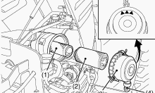
Since the air cleaner employed on Kubota V2403 engine is a dry type,
never apply oil to it. Open the evacuator valve once a week under
ordinary conditions - or daily when used in a dusty place. This will get
rid of large particles of dust and dirt. Wipe the inside air cleaner
clean with cloth if it is dirty or wet. Avoid touching the element
except when cleaning. When dry dust adheres to the element, blow
compressed air from the inside turning the element. Pressure of
compressed air must be under 205 kPa (2.1 kgf/cm2, 30 psi). Replace the
element every year or every 6 cleanings. Make sure the wing bolt for the
element is tight enough. If it is loose, dust and dirt may be sucked in,
wearing down the cylinder liner and piston ring earlier and thereby
resulting in poor power output. Do not over service the air cleaner
element. Over servicing may cause dirt to enter the engine causing
premature wear. Use the dust indicator as a guide on when to service.
Evacuator valve - Open the evacuator valve once a week under ordinary
conditions - or daily when used in a dusty place - to get rid of large
particles of dust and dirt. For the air cleaner with a dust cup
(optional) - Remove and clean out the dust cup before it becomes half
full with dust; usually once a week, or even every day if the working
surroundings are dusty. Install the air cleaner dust cup with "top"
indicated on the rear of the cup in the up position. (However, it may be
installed in either direction when the cover is placed at the lower
part.). If the dust cup is mounted incorrectly, dust or dirt does not
collect in the cup, and direct attachments of the dust to the element
will cause its lifetime to shorten to a great extent.
Kubota L4200, L5040, L5740, MX5100 -
Lubricating System
Checking oil level and adding engine oil
Check the engine oil level before starting or more than 5 minutes after
stopping the engine. Remove the oil level gauge, wipe it clean and
reinstall it. Take the oil level gauge out again, and check the oil
level. If the oil level is too low, remove the oil filler plug, and add
new oil to the prescribed level. After adding oil, wait more than 5
minutes and check the oil level again. It takes some time for the oil to
drain down to the oil pan. Engine oil capacity - 7.5-9.5 L.
Changing engine oil
Change oil after the initial 50 hours of operation and every 200 hours
thereafter. Remove the drain plug at the bottom of the engine, and drain
all the old oil. Drain oil will drain easier when the oil is warm. Add
new engine oil up to the upper limit of the oil level gauge.
Replacing the oil filter cartridge
Replace the oil filter cartridge. Apply a film of oil to the gasket for
the new cartridge. Screw in the cartridge by hand. When the gasket
contacts the seal surface, tighten the cartridge enough by hand.
Because, if you tighten the cartridge with a wrench, it will be
tightened too much. After the new cartridge has been replaced, the
engine oil level normally decreases a little. Thus, run the engine for a
while and check for oil leaks through the seal before checking the
engine oil level. Add oil if necessary.
Kubota L4200, L5040, L5740, MX5100 - Cooling
System
Radiator Cooling water
If the coolant temperature warning lamp lights up or if steam or coolant
does not stop squirting from the radiator overflow pipe, turn off the
load and keep the engine idling (Cooling-Down) for at least 5 minutes to
let it cool down gradually. Then stop Kubota V2403 engine and take the
following inspection and servicing. Check to see if the coolant runs
short or if there is any coolant leak. Check to see if there is any
obstacle around the cooling air inlet or outlet. Check to see if there
is any dirt or dust between radiator fins and tube. Check to see if the
fan belt is too loose. Check to see if radiator water pipe is clogged.
Checking coolant level, adding coolant
Remove the radiator cap, after the engine has completely cooled, and
check to see that coolant reaches the supply port. If the radiator is
provided with a recovery tank, check the coolant level of the recovery
tank. When it is between the "Full" and "Low" marks, the coolant will
last for one day's work. When the coolant level drops due to
evaporation, add water only up to the full level. Check to see that two
drain cocks; one is at the crankcase side and the other is at the lower
part of the radiator. If the radiator cap has to be removed, follow the
caution and securely retighten the cap. If coolant should be leak,
repair it or replace. Make sure that muddy or sea water does not enter
the radiator. Use clean, fresh water and 50% anti-freeze to fill the
recovery tank. Do not refill recovery tank with coolant over the "Full"
level mark. Be sure to close the radiator cap securely. If the cap is
loose or improperly closed, coolant may leak out and decrease quickly.
Checking radiator hoses and clamp bands
Check to see if radiator hoses are properly fixed every 200 hours of
operation or 6 months, whichever comes first. If hose clamps are loose
or water leaks, tighten hose clamp securely. Replace hoses and tighten
hose clamps securely, if radiator hoses are swollen, hardened or
cracked. Replace hoses and hose clamps every 2 years or earlier, if
checked and found that hoses are swollen, hardened or cracked. If the
coolant temperature warning lamp lights up or if steam or coolant does
not stop squirting from the radiator overflow pipe, turn off the load
and keep the engine idling (Cooling-Down) for at least 5 minutes to let
it cool down gradually. Then stop the engine and take the following
inspection and servicing. Check to see if the coolant runs short or if
there is any coolant leak. Check to see if there is any obstacle around
the cooling air inlet or outlet. Check to see if there is any dirt or
dust between radiator fins and tube. Check to see if the fan belt is too
loose. Check to see if radiator water pipe is clogged.
Adjusting Fan Belt Tension
Stop the engine and remove the key. Apply moderate thumb pressure to
belt between the pulleys. If tension is incorrect, loosen the alternator
mounting bolts and, using a lever placed between the alternator and the
engine block, pull the alternator out until the deflection of the belt
falls within acceptable limits. Replace fan belt if it is damaged. If
belt is loosen or damaged and the fan is damaged, it could result in
overheats or insufficient charging. Correct or replace belt.
Kubota L4200, L5040, L5740, MX5100 - Engine
Components
Compression Pressure
After warming-up the engine, remove the air cleaner, muffler, glow lead,
and glow plugs. Set a compression tester with the adaptor to the glow
plug hole. Crank the engine with the starter to operate the engine
approx. 200 to 300 min-1 (rpm). Measure a maximum value of the
compression pressure. Do the same steps twice for each cylinder.
Cylinder Head Cover and Glow Plug
Remove the glow lead and the glow plugs. Remove the cylinder head cover.
Check to see that the cylinder head cover gasket is not detective.
Tighten the head cover mounting screws to specified torque. Replace the
gasket of cylinder head cover with a new one. Adjust the direction of
the ditch to the terminal side when the seal is installed in the glow
plug. After installing the glow plug, make sure that the seal was set to
the specified position.
Overflow Pipe and Injectors
Remove the overflow pipe. Remove the injector clamp. Remove the injector
and its gasket. Do not disassemble the injector. Do not get the
injectors out of order. If the injectors get out of order, it is
necessary to perform injector correction. Store the injectors so they do
not get any dust in them. Attach the O-ring to the correct position on
the injector. After attaching gasket to the injector, attach the
injector to the cylinder head. Correctly set the clamp. Attach the
injector with screws. Check that the injector is attached securely. Do
not remove the injector dust protection cap until immediately before you
attach the injection pipe. To prevent the injector inlet connector from
turning when removing the injection pipe cap nut, use a counter wrench.
When the inlet connector becomes loose, replace the injector. If you
replace the injectors, it is necessary to perform injector correction.
Rocker Arm and Push Rods
Remove the screws of the rocker arm bracket. Remove the rocker arm
assembly. Remove the push rods. When you put the push rods on the
tappets, make sure that their ends are correctly engaged with the
grooves.
Kubota L4200, L5040, L5740, MX5100 - Cylinder
Head
Remove the cylinder head screw. Lift up the cylinder head to remove.
Remove the cylinder head gasket. Replace the cylinder head gasket with a
new one. Apply sufficient oil and tighten the cylinder head screws.
Tighten the cylinder head screws in a diagonal sequence. Start from the
center in the sequence. Tighten them equally, or the shape of the head
changes after some time.
Tappets
Remove the tappets from the crankcase. Before you install the tappets,
apply a thin layer of engine oil around them. Examine the contact
between tappets and cams that it turns correctly. If it is damaged,
replace the tappets.
Valves
Remove the valve caps. Push the valve spring retainer with the valve
spring replacer and remove the valve spring collets. Remove the valve
spring retainer and valve spring. Remove the valve. Clean the valve stem
and the valve guide hole, and apply engine oil sufficiently. After you
install the valve spring collets, lightly tap the stem tip to attach it
correctly with the plastic hammer.
Fan Drive Pulley
Lock the flywheel with the flywheel stopper. Remove the mounting nut of
the fan drive pulley with a 46 mm (1.8 in.) deep socket wrench. Remove
the fan drive pulley with a gear puller. Remove the feather key. Apply
grease to the splines of coupling.
Gear Case
Remove the hour meter gear case (if attached). Remove the gear case.
Remove the O-rings. Replace the gear case gasket and O-rings. Replace
the hour meter gear case gasket with a new one. Make sure that there are
4 O-rings in the gear case. Apply a thin layer of engine oil to the oil
seal. Then install the oil seal not to come off the lip. Before you
install the gear case gasket, apply an adhesive that does not become
dry.
Crankshaft Oil Slinger
Remove the crankshaft collar. Remove the O-ring. Remove the crankshaft
oil slinger. Attach the crankshaft collar after you install the gear
case to the cylinder body.
Idle Gear
Remove the external snap ring. Remove the idle gear collar. Remove the
idle gear.
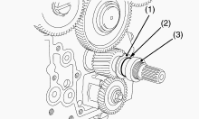
Camshaft and Balancer Shaft
Remove the camshaft set bolts and draw out the camshaft. Remove the
balancer shaft 1 set bolts and draw out the balancer shaft 1. Remove the
balancer shaft 2 set bolts and draw out the balancer shaft 2. When
install the balancer shaft 1 and 2, be sure to place the 4th cylinders
piston at the top dead center in compression then, align all mating
marks on each gear to assemble the timing gears, set the idle gear last.
Kubota L4200, L5040, L5740, MX5100 - Fuel
Camshaft
Remove the fuel feed pump. Remove the fuel camshaft stopper. Pull out
the fuel camshaft assembly. After attaching the fuel camshaft, store oil
in the pump room. Recommended oil amount about 110 cc.
Oil Pump
Remove the nut. Pull out the oil pump drive gear with a gear puller.
Remove the 4 mounting screws of the oil pump. Remove the oil pump.
Oil Pan and Oil Strainer
Remove the oil pan mounting screws and remove the oil pan. Remove the
oil strainer mounting screw, and remove the oil strainer. When
installing the oil strainer, be careful not to damage the O-ring. Apply
liquid gasket to the oil pan. Make sure that the liquid gasket coating
surface is free of water, dust and oil in order to keep sealing effect.
Carefully apply the adhesive evenly. Make sure the surfaces align when
mounting parts with a liquid gasket applied to them. Mount parts with a
liquid gasket within 10 minutes of application. Tighten the mounting
screws of the oil pan in diagonal sequence from the center to tighten
equally. After cleaning the oil strainer, install it. Attach the oil pan
with its central drain plug facing toward the air suction side.
Pistons
Fully clean the carbon in the cylinders. Remove the connecting rod cap.
Turn the flywheel and move the piston to top dead center. Lightly tap
the piston from the bottom of the crankcase with the grip of a hammer to
pull the piston out. Pull out the other piston in the same procedure as
above. Before you install the piston into the cylinder, apply sufficient
engine oil to the piston. When you install the piston into the cylinder,
point the mark on the connecting rod to the fuel supply pump side. Do
not change the combination of cylinder and piston. Align the position of
each piston by its mark. For example, mark "1" on the No. 1 piston. Set
the top ring with its gap (A) at 1.6 rad (90°) from the direction of the
piston pin. Then set the second ring and the oil ring with their gaps
(B), (C) at 2.09 rad (120°) from the top ring gap (A). Install the
pistons with a piston ring compressor carefully. When you install the
piston in position, do not give a damage to the layer of molybdenum
disulfide on the piston skirt. This layer can decrease the clearance
with the cylinder liner. Immediately after you press-fit the piston pin,
the piston is hot and the layer comes off easily. Only put in the piston
after its temperature decreases. When you replace the piston, look at
the code number on top of the piston. Use a replacement piston with the
same code number.
Piston Ring and Connecting Rod
Remove the piston rings with a piston ring tool. Remove the piston pin
to disconnect the connecting rod from the piston. When you install the
rings to the piston, set the manufacturer mark upward. When you install
the oil ring on the piston, set the expander joint on the opposite side
of the oil ring gap. When you install the piston pin, put the piston
fully in 80C (176F) oil for 10 to 15 minutes. Apply engine oil to the
piston pin. When you connect the piston and connecting rod, set the FW
mark on the piston head to the flywheel side. When you install the
piston into the cylinder, point the mark on the connecting rod to the
fuel supply pump.
Kubota L4200, L5040, L5740, MX5100 - Flywheel
Attach the stopper to the flywheel. Remove 2 flywheel screws. Put the 2
flywheel guide screws in the holes. Remove all the flywheel screws.
Remove the flywheel slowly along the flywheel guide screws. Do not use
an impact wrench. Serious damage will occur. The flywheel is very heavy,
so securely hold the flywheel when removing. Put in 2 flywheel guide
screws. Check that there are no metal particles that remain on the
flywheel mounting surfaces. Apply engine oil to the threads and the
flange seat face of the flywheel screw. Then attach the screw.
Confirmation of Top Dead Center
Remove the rocker arm. Align the 4 piston with top dead center and
remove the valve spring of the 4 cylinder. Insert an O-ring to prevent
the exhaust valve from falling into the cylinder and position the dial
gauge at the tip of the valve. While turning the flywheel to the left,
the largest deflection of the needle on the gauge indicates top dead
center so stop the flywheel in this position and set a tri-square as
indicated in the diagram and place a top dead center mark on the
reference line and flywheel on the engine body side. Note, in the case
the flywheel is turned too far, return it by turning to the right and
start over.
Confirmation of Crank Position Sensor Top Dead
Center Detection Position
Align the reference (20th for 4 cylinder models) pulser hole from the
area where there is no pulser hole on the outer circumference of the
flywheel with the crank position sensor mounting hole on the flywheel
housing. Insert a special tooling injection top correction jig into the
crank position sensor mounting hole and align the center of handle and
pulser. This position is the crank position sensor top dead center
detection position so position the tri-square on the reference line set
in the previous item and make a crank position sensor top dead center
detection position mark on the flywheel.
Bearing Case Cover
Remove the mounting screws of the bearing case cover. First, remove
inner screws and then external screws. Remove the bearing case cover.
The length of inner screws and external screws are different. Make sure
that you use the correct one at the correct position. Attach the bearing
case gasket and the bearing case cover gasket in the correct directions.
Put the casting mark UP of the bearing case cover upward, then install
the bearing case cover. Apply a thin layer of engine oil to the oil
seal. Then install the oil seal not to come off the lip. Tighten the
mounting screws of the bearing case cover with an equal force on the
diagonal line.
Crankshaft
Before you disassemble, measure the side clearance of crankshaft.
Measure it when you assemble again. Remove the screw 2 of the main
bearing case. Turn the crankshaft to set the crankpin of the third
cylinder to the bottom dead center. Pull out the crankshaft until the
crankpin of the second cylinder comes to the center of the third
cylinder. Turn the crankshaft by 2.09 rad (120°) counterclockwise to set
the crankpin of the second cylinder to the bottom dead center. Pull out
the crankshaft until the crankpin of the first cylinder comes to the
center of the third cylinder. Do the above steps again to pull out the
crankshaft completely.
Main Bearing Case Assembly
Remove the screws 1 of the main bearing case. Then remove the main
bearing case. Remove other main bearing cases as above. Clean the oil
channel in the main bearing case. Apply clean engine oil on the
bearings. Align the numbers on the main bearing case. When you install
the main bearing case, point the mark FLYWHEEL to the flywheel. When you
install the thrust bearing, point the oil groove externally. Install the
main bearing case assemblies in the initial positions. Since the
diameters of the main bearing cases are different, install them in the
sequence of their marks (A, B for 3 cylinders and A, B, C for 4
cylinders) from the gear case side. After you tighten the screw 1 of the
main bearing case to the specified torque, make sure that the main
bearing case moves smoothly.
Kubota L4200, L5040, L5740, MX5100 - Engine
Troubleshooting
Engine cranks slowly
Battery faulty or low charge - Charge or replace battery.
Faulty starter motor - Repair or replace starter motor.
Incorrect engine oil viscosity - Replace with proper engine oil.
Kubota V2203 engine will not crank
Discharged battery - Charge or replace battery.
Corroded battery terminals - Clean terminals.
Loose connection in starting circuit - Clean and tighten all
connections.
Defective starting switch - Replace switch.
Starting motor brushes dirty - Clean or replace brushes.
Jammed starter drive gear - Loosen starter motor to free gear.
Faulty starter motor - Replace motor.
Seized engine - Inspect and repair.
Engine will not start
Empty fuel tank - Fill tank with proper fuel.
Dirty or plugged fuel filter - Clean fuel filters.
Air in injection lines - Bleed air in injection lines.
Faulty fuel feed pump - Repair fuel feed pump.
Faulty fuel injection pump - Repair fuel injection pump.
Faulty governor - Repair governor.
Misadjusted controls - Adjust speed and stop controls.
Improper fuel injection timing - Adjust fuel injection timing.
Poor valve seating - Check for broken or weak valve springs, warped
stems, carbon and gum deposits and insufficient tappet clearance.
Damaged cylinder head gasket - Check for leaks around gasket when engine
is cranked; if a leak is found, replace gasket.
Worn or broken piston rings - Replace worn or broken rings; check
cylinders for out-of-round and taper.
Engine stops suddenly
Empty fuel tank - Fill fuel tank.
Air in fuel lines - Bleed fuel lines.
Governor malfunction - Repair governor.
Engine seized - Inspect and repair.
Engine slows unexpectedly
Overload - Locate cause for overload and rectify.
Fuel filter or fuel lines clogged - Inspect and unclog or replace.
Air in fuel system - Bleed air in fuel system.
Water in fuel - Remove water.
Misadjusted governor - Adjust governor.
Piston or bearing seizure - Repair damaged components; determine cause.
Engine will not run under full load
Clogged fuel filter - Clean fuel filter.
Faulty fuel feed pump - Repair fuel feed pump.
Worn fuel injection pump - Repair or replace fuel Injection pump.
Kubota V2203 engine knocks
Excessive bearing clearance - Inspect and repair.
Loose rod bolt - Inspect and repair.
Loose flywheel or coupling bolt - Tighten bolt.
Incorrect injection timing - Adjust timing.
Excessive fuel injected into cylinder - Inspect fuel injection pump and
injectors.
Low oil pressure
Oil leaks - Inspect and repair.
Excessive bearing clearance - Inspect and repair.
Clogged oil filter element - Clean or replace filter element.
Faulty oil pressure regulator valve - Repair oil pressure regulator
valve.
Low oil viscosity - Replace oil; check for dilution due to fuel leaking
into crankcase.
Overheating
Dirty cooling system - Flush cooling system.
Faulty thermostat - Replace thermostat.
Insufficient coolant flow - Check water pump; check for blockage in
system.
Insufficient coolant in closed system - Fill with proper coolant.
Air entering system - Check for loose clamps and damaged hoses.
________________________________________________________________________________
________________________________________________________________________________________
 SPECIFICATIONS
 LOADERS
 ENGINES
 INSTRUCTIONS
 PROBLEMS
________________________________________________________________________________________
 B2320
B2320 B2630
B2630 B2920
B2920 B3300SU
 BX2360
________________________________________________________________________________________
 L245
L245 L260
L260 L275
L275 L285
L285 L305
L305________________________________________________________________________________________
________________________________________________________________________________________
 D662
D662 D722
D722 D750
D750 D782
D782 D850
D850________________________________________________________________________________________
 LA302
LA302 LA304
LA304 LA340
LA340 LA344
LA344 LA351
LA351________________________________________________________________________________________
 BX2660
 L2501
L2501 L3240
L3240 L3540
L3540 L3940
L3940________________________________________________________________________________________
 D902
D902 D905
D905 D950
D950 D1005
D1005 D1100
D1100________________________________________________________________________________________
________________________________________________________________________________________
 B1630
B1630 BF400
BF400 BF400G
 LA181
LA181 LA203
LA203________________________________________________________________________________________
 LA211
LA211 LA243
LA243 LA271
LA271 LA272
LA272 LA301
LA301________________________________________________________________________________________
 L175
L175 L185
L185 L210
L210 L225
L225 L235
L235________________________________________________________________________________________
 D1105
D1105 D1503
D1503 D1703
D1703 D1803
D1803 V1200
V1200________________________________________________________________________________________
 L4400
L4400 L4600
L4600 L5040
L5040 L5740
L5740 MX4700
________________________________________________________________________________________
 LA352
LA352 LA364
LA364 LA401
LA401 LA402
LA402 LA403
LA403________________________________________________________________________________________
 LA434
LA434 LA463
LA463 LA481
LA481 LA482
LA482 LA504
LA504________________________________________________________________________________________
 V1205
V1205 V1305
V1305 V1505
V1505 V2203
V2203 V2403
V2403________________________________________________________________________________________
 B2710
B2710 BX23S
BX23S B3350
B3350 BX1880
 L4701
L4701________________________________________________________________________________________
 LA513
LA513 LA514
LA514 LA524
LA524 LA525
LA525 LA534
LA534________________________________________________________________________________________
 LA555
LA555 LA680
LA680 LA681
LA681 LA682
LA682 LA703
LA703________________________________________________________________________________________
 Z482
Z482 Z602
Z602 Z750
Z750 Z1100
Z1100 Z1300
Z1300________________________________________________________________________________________
 M100GX
 M135GX
 M6040
M6040 M8540
M8540 M95X
M95X________________________________________________________________________________________
 LA714
LA714 LA723
LA723 LA724
LA724 LA764
LA764 LA765
LA765________________________________________________________________________________________
 LA805
LA805 LA844
LA844 LA852
LA852 LA853
LA853 LA854
LA854________________________________________________________________________________________
 M5-091
 BX2680
 MX5200
 BX2380
 L3901
L3901________________________________________________________________________________________
 LA1002
 LA1055
 LA1065
 LA1153
 LA1154
________________________________________________________________________________________
 LA1251
 LA1301S
 LA1353
 LA1403
 LA1601S
________________________________________________________________________________________
 LA1854
 LA1944
 LA1953
 LA2253
 LM2605