
________________________________________________________________________________
Massey Ferguson 6470 Tractor Specs Overview

Massey Ferguson 6470 Tractor Engine
Power at 2200 rpm, ISO hp (kW) - 125 (91)
Model - PERKINS EEM 1104C-E44TA
Number of cylinders/displacement - 4 / 4.4 Turbo
Injection pump - Bosch VP30
Fan - Viscostatic
Intercooler - Air
Alternator - 80 A
MF 6470 Tractor Gearbox
Gearbox model - GBA20 (4x4)
Clutch/shuttle - Power Shuttle
Type - Dynashift
AutoDrive - optional
Creeper unit 4/1 - optional
Creeper unit 14/1 - optional
Massey Ferguson 6470 Tractor Rear axle
Axle model - GPA20
Final drives - HD
Axle shaft D - 76 mm
Flanged shaft - standard
Brake discs per trumpet housing - 1
Hand brake discs - 3
Differential lock - Dog clutch
Linkage
Stabilisers - telescopic
Multi-hole drawbar - optional
3-point linkage - Cat. 2/3, hook or ball type
Clevis hitch - Fast-setting or pin-adjusting scale
Automatic clevis hitch - Fast-setting or pin-adjusting scale
Hitch stud - Stud or auto-hitch
Swinging drawbar - standard
Roller type swinging drawbar - optional
MF 6470 Tractor Power take-off
Type - Interchangeable / shiftable shaft
540/1000/eco - optional
750/1000 - optional
Number of clutch discs - 4
PTO brake - hydraulic
Proportional PTO - optional
Automated PTO - optional
Front power take-off - optional
Massey Ferguson 6470 Tractor Front axle
Model - AG 105
Type - Fixed
Rotational direction - Clockwise
Number of clutch discs - 5
Swivelling mudguard (4WD) - optional
2-wheel drive - optional
Front linkage (optional) - 2.5 T
MF6470 Tractor
Hydraulics
Open Centre 57 l/min - optional
TFLS 100 l/min - optional
Closed Centre 110 l/min - optional
Orbitrol steering - 125 cc
Brake master cylinder - standard
Braking assistance - optional
Trailer brake - optional
Auxiliary spool valves (maximum number) - 4 electrohydraulic (2 SMS) or
4 mechanical
Couplers - Decompression
Electronics
Transmission control - AUTOTRONIC 3
Instrument panel - DCC2
Linkage controller - EHRC
Draft sensors - 2
Sensor capacity - 4 T (standard) or 6 T (optional)
Datatronic - optional
Dual control (front and rear) - optional
TIC with/without draft sensor - optional
Fieldstar - optional
Cab
Suspension - optional
Rear-view mirrors - manual (standard) or electric (optional)
Air conditioning - manual (standard) or automatic (optional)
Standard bonnet - Fixed
Bonnet option - Hinged
Standard roof - standard
High-visibility roof - optional
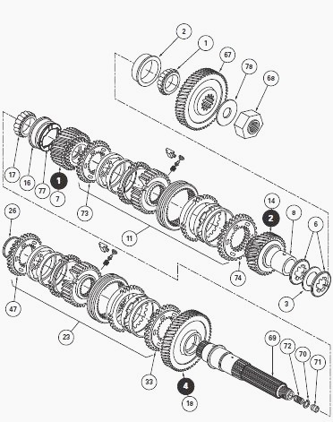
MF 6470 Tractor Gearbox - Mainshaft
The mainshaft (69) is mounted on two taper roller bearings (1) (17) with
bearing cups (2) (16), resting in the two lower bearings of the main
unit. Each bearing cup has a root face giving it maximum contact with
the housing. At the front it receives the drive pinion (67).
Between the two lower bearings, it holds the 1st (7) and 2nd (14) idle
mounted drive pinions, as well as the 1st and 2nd gear synchromesh
assembly (11), whose hub is held by splines. At the rear, it holds the
4th gear drive pinion (18) and the 3rd and 4th gear synchromesh assembly
(23).
The 1st, 2nd (11) and 3rd, 4th (23) synchronizers are of the double cone
type. The rear bore contains a needle bearing that holds the front end
of the output shaft. The turning parts are lubricated by a central
channel and radial bores.
The taper roller bearings are mounted with preload obtained by shim(s)
(3) inserted between the serrated washers (6) positioned against the
drive pinion (67) and the ring (8). A washer (77) with flat sections
acts as a stop for the 1st drive pinion (7).
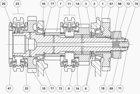
Parts list
(1) Bearing cone, (2) Bearing cup, (3) Shim(s), (6) Serrated washers,
(7) 1st drive pinion, (8) Ring, (11) 1st, 2nd double cone synchronizer,
(14) 2nd drive pinion, (16) Bearing cup, (17) Bearing cone, (18) 4th
drive pinion, (23) 3rd, 4th double cone synchronizer, (26) Circlip, (33)
4th synchronizer cone, (47) 3rd synchronizer cone, (67) Drive pinion,
(68) Nut, (69) Mainshaft, (70) Snap ring, (71) Lubricating pipe, (72)
Spring, (73) 1st synchronizer cone, (74) 2nd synchronizer cone, (77)
Washer with flat sections, (78) Tab washer
Disassembling and reassembling the
shaft
- To take out the mainshaft, it is necessary to remove the gearbox.
- Split the MF 6470 Tractor between the gearbox and the
rear axle.
- Split the gearbox from the engine. Remove the selector cover.
- Remove the input unit assembly. Remove the layshaft.
- Remove the selector rail and the forks. Remove the output shaft. Take
off circlip (26).
- Remove 3rd, 4th synchronizer (23) and cones (33) (47). Note the
assembly order.
- Position locking tool and the holding sleeve of shaft (69), made
locally.
- Remove lubricating pipe (71) and spring (72).
- Remove the safety device from nut (68) and loosen with socket.
- Remove drive pinion (67) with cone (1).
- Remove washers (6) and shim(s) (3). Remove the tool and sleeve.
- Pull the shaft out of the housing backwards, while holding the 1st,
2nd pinion assembly together.
- Remove 1st, 2nd pinion and synchronizer (11) assembly with ring (8).
Remove cups (16) (2).
- If necessary, remove washer with flat sections (77), extract cone (1)
(17) and remove snap ring (70).
- Clean the housing and the mating faces.
- With compressed air, check that no channels in the MF6470 Tractor
gearbox or in the shaft are clogged.
- Clean and check all components. Replace any defective parts. Lubricate
cones, cups, bearings bores and the ring.
- Using a suitable fixture, press fit bearing cone (17) on shaft (69)
(if removed). Fit snap ring (70). Install cups (2) (16).
- Install the 1st, 2nd pinion, synchronizer (11), cones (73) (74) and
ring (8) assembly.
- Fit the shaft from the rear of the housing while holding the pinion /
synchronizer assembly together, making sure that ring (8) is correctly
fitted in pinion (14).
- Install locking tool and locally made holding sleeve. Force-fit cone
(1) on pinion (67).
- Install washers (6) separated by a number of shims (3) sufficiently
thick to obtain a temporary clearance of 0.10 to 0.15 mm approx in
preparation for shimming with preload.
- Install pinion (67) on shaft (69). Fit the nut (68) using socket and
tighten to 130 - 170 Nm.
- Remove the tool and sleeve. Shim the shaft.
- Position the dial gauge feeler pin at the end of the shaft.
- From the front of the housing, pull the shaft, turning it alternately
from left to right in order to correctly seat the cones in the cups.
- Reset the dial gauge to zero. Repeat operation, but this time by
pushing.
- Depending on the clearance measured, select the thickness of final
shims required and necessary to obtain a preload: P1 = 0.14 mm to 0.20
mm. If possible, shim to the maximum tolerance.
- Install the locking tool and the holding sleeve. Loosen nut (68).
- Remove pinion (67). Position shims (3) selected during measure
operation between two washers (6).
- Install the pinion. Degrease the thread of the shaft with a solvent.
- Lightly smear new nut (68) with Loctite 270 then tighten to 130 - 170
Nm.
- Lock the nut in place by bending the collar into the grooves using a
suitable drift.
- Insert spring (72) and lubricating pipe (71) in the shaft.
- Remove the tool and the holding sleeve.
- Fit pinion (18), 4th, 3rd synchronizer cone (33) (47) and 3rd, 4th
synchronizer (23). The lubrication grooves are directed towards the 4th
pinion (18).
- Fit a new circlip (26), opening it as little as possible. After
assembly, check that the circlip is not bent.
- Manually check: the end play of the pinions / the rotation of the
shaft and its pinions.
- Check that the 1st, 2nd synchronizer operates properly. Install and
shim the output shaft.
- Refit the layshaft. Refit the input unit assembly.
- Shim the layshaft. Install the forks and the selector rail.
- Refit the selector cover. Couple the Massey Ferguson 6470 Tractor
gearbox to the engine.
- Couple the gearbox and the rear axle.
- Check operation of electric circuits. Carry out the road test on the
controls.
- Check for hydraulic tightness of the unions and mating faces (selector
cover, gearbox on rear axle).
________________________________________________________________________________
________________________________________________________________________________________
 SPECS
SPECS LOADERS
 MAINTENANCE
 PROBLEMS
________________________________________________________________________________________
 MF 1523
 MF 1531
 MF 135
 MF 1547
 MF 1635
________________________________________________________________________________________
________________________________________________________________________________________
 231
231 231S
231S 235
235 240
240 241
241________________________________________________________________________________________
 255
255 265
265 274
274 285
285 375
375________________________________________________________________________________________
________________________________________________________________________________________
 916X Loader
 921X Loader
 926X Loader
 931X Loader
 936X Loader
________________________________________________________________________________________
 941X Loader
 946X Loader
 951X Loader
 956X Loader
 988 Loader
________________________________________________________________________________________
 1655
1655 GS1705
 1742
1742 2635
2635 4608
4608________________________________________________________________________________________
 1080
1080 1100
1100 2615
2615 3050
3050 3060
3060________________________________________________________________________________________
 4708
4708 5455
5455 5450
5450 5610
5610 5613
5613________________________________________________________________________________________
 DL95 Loader
 DL100 Loader
 DL120 Loader
 DL125 Loader
 DL130 Loader
________________________________________________________________________________________
 DL135 Loader
 DL250 Loader
 DL260 Loader
 L90 Loader
 L100 Loader
________________________________________________________________________________________
 6499
6499 7480
7480 7618
7618 7726
7726 1533
1533________________________________________________________________________________________
 2604H
2604H 2607H
2607H 4455
4455 4610M
4610M 4710
4710________________________________________________________________________________________
 L105E Loader
 L210 Loader
 1014 Loader
 1016 Loader
 1462 Loader
________________________________________________________________________________________
 1525 Loader
 1530 Loader
 232 Loader
 838 Loader
 848 Loader
________________________________________________________________________________________
 5712SL
 6713
6713 6715S
6715S 7475
7475 7615
7615________________________________________________________________________________________
 7716
7716 7724
7724 8240
8240 8650
8650 8732
8732________________________________________________________________________________________
 246 Loader
 1036 Loader
 1038 Loader
 1080 Loader
 856 Loader