
________________________________________________________________________________
Massey Ferguson 3050, 3060, 3080, 3125 Rear Axle - Lift cover
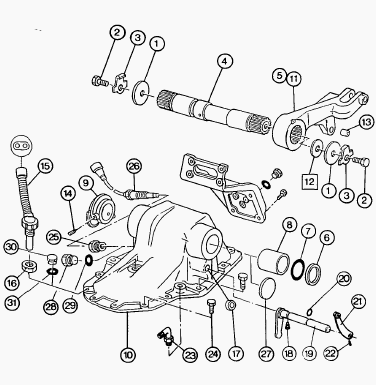
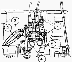
The lift cover is mounted on the upper face of the rear axle housing.
The shaft (4) which has the two lift arms (5) and (11) splined to it is
supported by bushes (8). Cam (9) on the lift shaft (4) provides the
means for sensor (26) to monitor position of lift arms. This information
is transmitted to the Electronic Linkage Control (ELC) system. To ensure
correct play between the lift arms and the cover, shims are fitted on
the left hand end of the shaft. The rear face of the lift cover supports
the auxiliary spool valves. The vehicle speed sensor (15) is screwed in
the front oi the cover. The cover also supports lever (21) for economy
(4 speed) PTO.
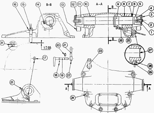
Parts list - (1) Washer, (2) Bolt, (3) Retainer, (4)
Lift shaft, (5) Right-hand lift arm, (6) Nylon ring, (7) O-ring, (8)
Bush, (9) Cam, (10) Lift cover, (11) Left-hand lilt arm, (12) Shim(s),
(13) Bush, (14) Set screw, (15) Vehicle speed sensor, (16) Nut, (17) Cup
plug (2-speed PTO), (18) Screw (4-speed PTO), (19) Control finger
(4-speed PTO), (20) О-ring (4-speed PTO), (21) Lever (4-speed PTO), (22)
Screw (4-speed PTO), (23) Elbow connector, (24) Bolt, (25) Nut, (26)
Position sensor, (27) Cup plug, (28) Threaded plug, (29) Seal, (30)
Threaded plug, (31) Seal
Massey Ferguson 3050, 3060, 3080, 3125 - Lift
Cover Removal and Disassembly
Removal
Remove the sheet metal. Remove the rear fastening screws to the cab
(remove only the central and lower screws to the guard plates to gain
access to the cab fastening screws). Raise the cab. Place a block
between the cab and the trumpets. Disconnect: the supply hose to the
spool valve; supply hose to the lift valve; return hose. Remove the
bolts for the spool valve support. Remove the support swinging the
assembly out of the way, without disconnecting the controls.
Disconnect: vehicle sensor wire assembly (Autotronic, Datatronic);
position sensor wire assembly; differential lock pipe; cable (4-speed
PTO, if fitted); cable(shiftable PTO, if fitted). Unscrew the pipe at
both ends and remove the support for the trailer brake connector if
fitted. Remove the upper pins from the rams and lift rods. Remove the
fastening bolts for the cover. The PTO control cable supports (depending
on the version) are fixed by the bolts for the cover. Lift there over
and remove it.
Disassembly
Place the cover on a work bench. Remove the elbow connector. Unscrew the
nut (16) and remove the vehicle speed, sensor (15). Unscrew the nut (25)
and remove the position sensor (26). For MF 3050, 3060, 3080, 3065,
3070, 3095, 3120, 3125 tractors equipped with economy 4-speed, carry out
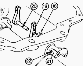
operations. Undo the Allen screw (22) in the lever (21). Undo the screw
(18).
Remove the control finger (19). Remove the O-ring (20). Flatten tabs
locking the bolts (2) retaining the lift arms. Undo the screws. Remove
the washers (1). Remove the shim(s). Remove the lift arms (5) and (11).
Remove the nylon rings (6) and the O-rings (7). Remove the set screws
(14) in the cam (9). Withdraw the lift shaft (4) from the cover. Remove
the cam (9). Withdraw the bushes (8). Remove the cup plug (17) (2-speed
PTO).
Massey Ferguson 3050, 3060, 3080, 3125 - Lift
Cover Reassembly
The bushes (13) are mounted with Loctite 648 at a distance of 40.50 mm
from the face. Clean and check the parts. Replace any which are
defective. Clean the joint faces of the lift cover and of the spool
valve support. Fit the bushes in the cover. Fit the cup plug (17)
smeared with Loctite 542 flush with the cover (2-speed PTO). Mount the
lift shaft (4) and the cam (9) in the cover. Ensure that the direction
of the shaft and the position of the cam are correct. Tighten the set
screws (14) smeared with Loctite 241 to a torque of 5 Nm.
Apply this torque so as not to deform the cam. Position the O-rings (7)
and the nylon rings (6). Note: Protect the splines of the shaft.
Lubricate the О-rings before mounting. Grease the splines of the shaft
(4) (Anti-Seize Grease or equivalent). Fit the lift arm (5) (sensor
side), the washer (1). the retainer (3) and the screw (2). Grease the
face of the cover (Anti-Seize Grease or equivalent) before fitting the
arms. Tighten the screw (2) so as to align two flat sides of the screw
head with the two tabs of the retainer(3). Bend back the tabs.
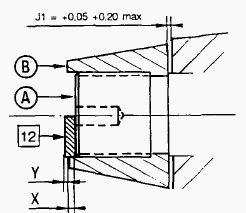
Carry out shimming of the shaft (4) to obtain: J1 = +0.05 to +0.20
maximum. Mount the arm (11), the washer (1) and the bolt (2). Grease the
face of the cover (Anti-Seize Grease or equivalent) before mounting the
arm. Tighten the bolt so as to position the lift arms (5) and (11)
correctly on the shaft. Remove the bolt (2) and the washer (1) at the
left end of the shaft. Measure the distance between face A of the shaft
and face В of the arm using a depth gauge. By measuring dimension X,
determine the thickness of spacers Y needed to obtain: J1 = +0.05 to
+0.20 maximum. J1 = X + Y.
Mount the previously selected shims, the washer (1), the retainer (3)
and the bolt (2). Tighten the bolt (2) so as to align two flat sides of
the screw head with the two tabs of the retainer (3). Bend back the
tabs. For MF 3050, 3060, 3080, 3065, 3070, 3095, 3120 tractors equipped
with economy 4-speed PTO, carry out operations. Refit the finger (19).
Mount the O-ring (20) from the exterior side of the cover. Smear the
screws (18) and (22) with Loctite 241 and tighten. Check that the
control functions smoothly. Fit the elbow connector (23).
Massey Ferguson 3050, 3060, 3080, 3125 - Lift
Cover Refitting
Clean the joint face of the cover on the rear axle housing. Smear the
joint face with a sealing compound (Master Joint 510 Loctite or
equivalent). Lift cover into position. When refitting the cover, ensure
that the supply pipe of the differential lock and the control finger
(4-speed economy PTO) engage properly in their respective positions.
Mount the supports for the PTO control cables (depending on the version)
and fit the bolts (24) of the cover (10).
Tighten to the following torque: 12 mm diameter bolt = 72-96 Nm, 16 mm diameter bolt = 160-200 Nm. A heavy-duty cover and five new bolts (24) has been released on MF 3125 tractor. The tightening torque of 16 mm diameter bolts is 240-320 Nm instead of 160-200 Nm. Refit the upper pins to the rams and lift rods.
Refit the trailer brake valve support if fitted. Retighten the pipe at both ends. Refit: differential lock supply pipe (3); cable (4) (4-speed PTO, if fitted); cable (5) (shiftable PTO, if fitted). Fit the vehicle speed sensor (15) with Loctite 577 Sensor Sealing or equivalent (Autotronic, Datatronic tractors). Screw in the speed sensor into contact with the crown wheel, without forcing it.
Unscrew the sensor 3/4 of a turn so as to obtain a clearance of approx.
1 mm between the sensor and the crown wheel. Tighten the nut (16)
moderately. Connect the sensor. Fix the harness assembly with a clip.
Clean the joint face of the spool valve support. Coat the joint face of
the spool valve support with a sealing compound (Master Joint 510
Loctite or equivalent). Refit the support and spool valve assembly.
Smear the thread of the two lower screws (4) with Loctite 510. Fit and
tighten the bolts (4) in the spool valve support to a torque of 50-70
Nm. Reconnect: supply hose (1) to the spool valve; supply hose (3) to
the lift valve; return hose (2). Adjust the PTO control (4-speed) and
the PTO control (shiftable). Remove the blocks between the cab supports
and the trumpets. Position the cab. Refit the rear fastening screws of
the cab.
Tighten the nuts to 27-35 Nm and the lock-nuts smeared with Loctite 270 to 13-20 Nm. Refasten the guard plates. Fit and adjust the position sensor. Smear the thread of the sensor (26) with a sealing compound (Hylomar or equivalent), then screw in the sensor a few turns and connect the harness. Start the engine. Using the external control, make sure that the lift arms are in the fully raised position (relief valve blowing).
Stop the engine, then make a mark on the cover and on one arm. Screw in the sensor (without forcing it) until it meets the cam (9) and unscrew by approximately one turn (1.5 mm). Fix the harness. Start the engine. Using the internal control, lower and raise the lift arms. Check the position of the moving mark on the arm. The difference between the two marks should be approx. 3 mm. If the difference is greater than 3 mm, unscrew the sensor slightly. If the difference is less than 3 mm, retighten the sensor slightly.
Tighten the nut (25) to a torque of 25 Nm using a suitable spanner. Check for leaks: at the joint between the lift cover and the spool valve support, at the hydraulic connectors. Refit the sheet metal. Version without lift - The holes of the shaft (4) are plugged with caps (27) sealed with Loctite 542. The position sensor (26) is replaced with a threaded plug (28) equipped with a seal (29). Version without Autotronic - The vehicle speed sensor (15) is replaced with a threaded plug (30) equipped with a seal (31).
________________________________________________________________________________
________________________________________________________________________________
________________________________________________________________________________________
 SPECS
SPECS LOADERS
 MAINTENANCE
 PROBLEMS
________________________________________________________________________________________
________________________________________________________________________________________
| MF TRACTORS SPECIFICATIONS |
 130
130 133
133 145
145 155
155 158
158________________________________________________________________________________________
 165
165 175
175 185
185 188
188 230
230________________________________________________________________________________________
 254
254 254S
254S 284S
284S 294
294 353
353________________________________________________________________________________________
 290
290 362
362 375
375 390
390 398
398________________________________________________________________________________________
 399
399 590
590 690
690 1010
1010 1030
1030________________________________________________________________________________________
 1020
1020 1150
1150 2620
2620 2640
2640 2645
2645________________________________________________________________________________________
 1540
1540 1736
1736 2660
2660 3065
3065 3095
3095________________________________________________________________________________________
 3650
3650 3680
3680 4255
4255 4355
4355 4370
4370________________________________________________________________________________________
 3630
3630 3635
3635 4245
4245 4445
4445 4609
4609________________________________________________________________________________________
 4710
4710 5435
5435 5475
5475 5610
5610 5711
5711________________________________________________________________________________________
 6150
6150 6170
6170 6180
6180 6270
6270 6290
6290________________________________________________________________________________________
 6445
6445 6499
6499 6614
6614 6713
6713 7465
7465________________________________________________________________________________________
 7495
7495 7614
7614 7622
7622 7715
7715 7726
7726________________________________________________________________________________________
 8210
8210 8270
8270 8650
8650 8727
8727 GC1705
________________________________________________________________________________________
| MF FRONT END LOADERS |
 1464 Loader
 1466 Loader
 1040 Loader
 1070 Loader
 905 Loader
________________________________________________________________________________________
 906 Loader
 915 Loader
 916 Loader
 921 Loader
 926 Loader
________________________________________________________________________________________
 931 Loader
 933 Loader
 936 Loader
 938 Loader
 939 Loader
________________________________________________________________________________________
 940 Loader
 941 Loader
 945 Loader
 946 Loader
 948 Loader
________________________________________________________________________________________
 949 Loader
 950 Loader
 951 Loader
 955 Loader
 956 Loader
________________________________________________________________________________________
 958 Loader
 960 Loader
 961 Loader
 965 Loader
 966 Loader
________________________________________________________________________________________
 968 Loader
 975 Loader
 976 Loader
 978 Loader
 985 Loader
________________________________________________________________________________________
 FL.3114 X
 FL.3419 X
 FL.3522
 FL.3615
 FL.3619
________________________________________________________________________________________
 FL.3817
 FL.3819
 FL.3823
 FL.4018
 FL.4121
 916X Loader
 921X Loader
 926X Loader
 931X Loader
 936X Loader
________________________________________________________________________________________
 941X Loader
 946X Loader
 951X Loader
 956X Loader
 988 Loader
________________________________________________________________________________________
 FL.4125
 FL.4227
 FL.4124
 FL.4220
 FL.4323
________________________________________________________________________________________
 FL.4327
 FL.4621
 FL.4624
 FL.4628
 FL.5033
________________________________________________________________________________________
 DL95 Loader
 DL100 Loader
 DL120 Loader
 DL125 Loader
 DL130 Loader
________________________________________________________________________________________
 DL135 Loader
 DL250 Loader
 DL260 Loader
 L90 Loader
 L100 Loader
________________________________________________________________________________________
 L105E Loader
 L210 Loader
 1014 Loader
 1016 Loader
 1462 Loader
________________________________________________________________________________________
 1525 Loader
 1530 Loader
 232 Loader
 838 Loader
 848 Loader
________________________________________________________________________________________
 246 Loader
 1036 Loader
 1038 Loader
 1080 Loader
 856 Loader
________________________________________________________________________________________
| MF TRACTORS MAINTENANCE |
 1010
1010 1020
1020 1030
1030 1035
1035 1040
1040________________________________________________________________________________________
 1045
1045 1080
1080 1085
1085 1120
1120 1125
1125________________________________________________________________________________________
 1140
1140 1160
1160 1165
1165 1180
1180 1190
1190________________________________________________________________________________________
 1205
1205 1210
1210 1215
1215 1220
1220 1225
1225________________________________________________________________________________________
 1230
1230 1233
1233 1235
1235 1240
1240 1260
1260________________________________________________________________________________________
| MF TRACTORS TROUBLESHOOTING | ||||
| 1652 | 1749 | 2620 | 2725 | 2805 |
| 3050 | 3120 | 3640 | 3709 | 4245 |
| 4455 | 5320 | 5455 | 5613 | 6150 |
| 6280 | 6480 | 6615 | 7618 | 7720 |