
________________________________________________________________________________
MF 5450, 5455 Power Shuttle Speedshift - Removing and install
Removing, splitting and disassembling the
planet carrier assembly
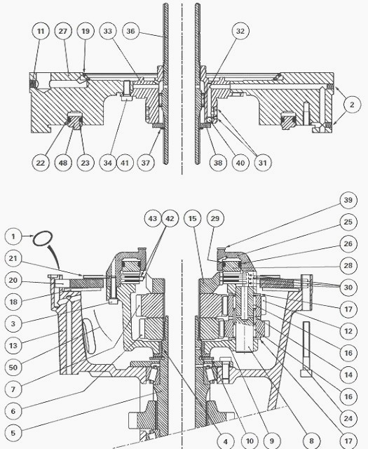
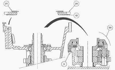
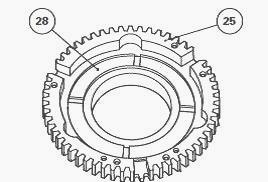
Remove the brake disc (21), thrust plate (20), Belleville washer (18)
and planet carrier assembly (50).
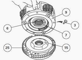
Put the planet carrier assembly on a workbench with the unit (9) turned
upwards. Remove the screws (3). Separate the unit (9) from Massey
Ferguson 5450, 5455
hydraulic cover plate (25) while holding sun gears (6) and (7).
The text and figures in this section concern the disassembly of a planet
carrier for a forward speed of 40 kph. Remove the input sun gear (7),
visually identifying the
direction of the lubricating grooves.
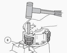
Drive out the pins (8) using a drift and a hammer. The pins are fitted
tight in the thickest part of the planet carrier with the lubrication
hole turned towards the
hydraulic cover plate (25). Remove the planet gears (12).
Recover needle roller bearings (16), spacers (14) and washers (17).
Remove the output sun gear (6).
Disassembling the MF 5455, 5450 hydraulic cover plate
Remove the splined hub (15). Remove the intermediate plates (30), discs
(42) and spring washers (43).
The clutch consists of:
- two friction discs;
- two spring washers;
- three intermediate plates.
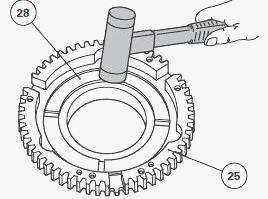
Remove the piston (28) by lightly tapping the cover plate (25) on a
wooden block or using a jet of compressed air. Remove the seals (26) and
(29) and discard
them.
Reassembling the planet carrier

Clean and check all components. Replace those that are defective.
Lubricate the needle roller bearings (16). Make sure that the radial
holes and axial channel for
the lubrication of pins (8) are not blocked.
Massey Ferguson 5455, 5450 Tractor speed can be between 30 and 40 kph.
Each speed is obtained by turning the planet gears and sun gears of the
Speedshift
epicyclic gear train. The sun gears have different numbers of teeth: sun
gear (6): 36 teeth/ sun gear (7): 39 teeth.
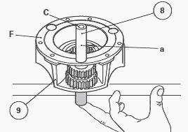
The text and figures in this section concern the reassembly of a planet
carrier for a forward speed of 40 kph. Put the output sun gear (6) in
the unit (9), turning the
sun gear lubricating grooves towards face "F" of the unit.
Install the needle roller bearings (16), separated by a spacer (14) in a
planet gear (12). Put an "assembled" planet gear in the unit, the
18-tooth gear turned.
Each
double planet gear is identified with one, two or three punchmarks on
one of its faces which is not necessarily the 18-tooth gear. In this
case, make the same marks
on the aforementioned gear using an appropriate pen. A punchmark
corresponds to the alignment of two teeth. Position the washers (17).
Centre the planet gear and washers with a guide pin O 16 mm, L = 80 mm.
Insert the pin (8) into the free bore on face "F" of the unit (9)
Install it partially set back,
with the radial lubricating hole "a" turned outwards and the end of
central channel "C" turned towards face "F".
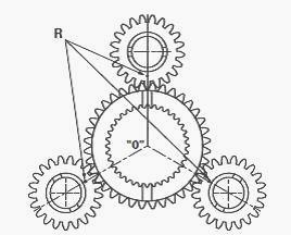
Repeat steps to assemble the two other planet gears. During these
operations, position the three planet gears according to marks "R" so
that they run in a line
corresponding with "O".
After final assembly of the pins (8), check again that the marks are
correctly aligned. Incorrect alignment may make it impossible to
assemble combined parts or
cause damage to the epicyclic gear train. Install the input sun gear (7)
with the lubricating groove turned towards the output sun gear (6).
Install the MF 5450, 5455 tractor hydraulic cover plate
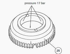
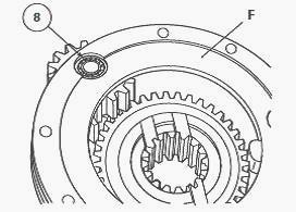
Clean and check all components. Replace those that are defective. Make
sure that the three holes of the 17-bar channel on the hydraulic cover
plate (25) are not
blocked. Install the lubricated seals (26) and (29) and onto the piston
(28).
Lubricate the mating faces of piston seals in the hydraulic cover plate.
Position the piston in the cover plate, turning the grooves towards the
operator. Install the
piston (28) using a plastic hammer, gradually and alternately striking
around the circumference of the piston.
Check that there are no fragments of "O" rings after fitting. Install
the splined hub (15). Install an intermediate plate (30), a disc (42)
and a spring washer (43).
Continue stacking parts, ending with an intermediate plate. Arrange the
cut section of spring washers in opposite directions.
Assembling the planet carrier
Screw two diametrically opposed guide studs in the Massey Ferguson 5450,
5455 hydraulic cover plate (25). Assemble the planet carrier unit (9) on
the hydraulic
cover plate (25) while holding the sun gears (6) and (7).
Position the unit and the cover plate so that the balancing marks
(ground in marks) are on opposite sides as far as possible. Reinstall
the screws (3). They must be
tightened to a torque of 14 - 20 Nm.
Strike pins (8) definitively
against the hydraulic cover plate (25) with a pin punch. Check: the
discs (42) are not compressed; the
planet gears (12) and sun gears (6) and (7) turn freely.
Install the planet carrier assembly (50) on the shaft (5). Position the
Belleville washer (18). Position the thrust plate (20) in the housing
(13). Install the brake disc (21)
on the planet carrier assembly.
Assembling and install the MF 5450, 5455 tractor front cover plate
Clean the cover plate. Make sure that the 17-bar channel and the
lubrication channel are not blocked. Check that the sealing rivets (2)
and (11) are present. Install
the seals (22) and (23) on the piston (48). Lubricate the mating faces
of the piston seals in the cover plate (27).
Position the piston in the cover plate, turning the grooves towards the
operator. Install the piston (48) using a plastic hammer, gradually and
alternately striking
around the circumference of the piston. Check that there are no
fragments of "O" rings after fitting.
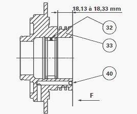
If work is necessary on the ring carrier (33):
- check that the channels are not blocked and that the ball bearing (40)
is correctly crimped in its port.
- If necessary, Install the needle roller bearing (32) 18.13 to 18.33 mm
from face "F";
- position the ring carrier on the cover plate, making sure that the low
pressure (17 bar) and lubrication holes correspond respectively with
those on the cover plate;
- Install and tighten screws (34) and (41), lightly smeared with Loctite
242 or similar, to a torque of 25 - 35 Nm.
Check that the lubrication holes on the shaft (36) are not blocked.
Slide the shaft in the ring carrier. Reinstall the washer (38) and
circlip (37). Test-Install the new
rings (31), making sure they turn freely in the grooves. After this
check, remove the rings and smear with miscible grease.
Install the rings in their respective grooves, making sure:
- that they do not exceed the circumference of the ring carrier;
- their ends overlap correctly. The slightest damage to rings may cause
a leak followed by a pressure drop and incorrect operation of the
Speedshift.
Smear the washer (39) with grease and Install it on the ring carrier
(33). Reinstall the new seals (1) on the housing (13). Reinstall the
shaft (36), ring carrier (33) and
front cover plate (27) assembly using the same procedure as for removal.
Install and tighten the screws (24) to a torque of 36 - 46 Nm, with the
thread lightly
smeared with Loctite 242 or similar.
Remove the makeshift lifting tool. Reinstall the Power Shuttle reverse
clutch. Reinstall the input unit and the Power Shuttle forward clutch.
Reinstall the spacer.
Reconnect the tractor between the engine and the gearbox.
________________________________________________________________________________
________________________________________________________________________________________
 SPECS
SPECS LOADERS
 MAINTENANCE
 PROBLEMS
________________________________________________________________________________________
 MF 1523
 MF 1531
 MF 135
 MF 1547
 MF 1635
________________________________________________________________________________________
________________________________________________________________________________________
 231
231 231S
231S 235
235 240
240 241
241________________________________________________________________________________________
 255
255 265
265 274
274 285
285 375
375________________________________________________________________________________________
________________________________________________________________________________________
 916X Loader
 921X Loader
 926X Loader
 931X Loader
 936X Loader
________________________________________________________________________________________
 941X Loader
 946X Loader
 951X Loader
 956X Loader
 988 Loader
________________________________________________________________________________________
 1655
1655 GS1705
 1742
1742 2635
2635 4608
4608________________________________________________________________________________________
 1080
1080 1100
1100 2615
2615 3050
3050 3060
3060________________________________________________________________________________________
 4708
4708 5455
5455 5450
5450 5610
5610 5613
5613________________________________________________________________________________________
 DL95 Loader
 DL100 Loader
 DL120 Loader
 DL125 Loader
 DL130 Loader
________________________________________________________________________________________
 DL135 Loader
 DL250 Loader
 DL260 Loader
 L90 Loader
 L100 Loader
________________________________________________________________________________________
 6499
6499 7480
7480 7618
7618 7726
7726 1533
1533________________________________________________________________________________________
 2604H
2604H 2607H
2607H 4455
4455 4610M
4610M 4710
4710________________________________________________________________________________________
 L105E Loader
 L210 Loader
 1014 Loader
 1016 Loader
 1462 Loader
________________________________________________________________________________________
 1525 Loader
 1530 Loader
 232 Loader
 838 Loader
 848 Loader
________________________________________________________________________________________
 5712SL
 6713
6713 6715S
6715S 7475
7475 7615
7615________________________________________________________________________________________
 7716
7716 7724
7724 8240
8240 8650
8650 8732
8732________________________________________________________________________________________
 246 Loader
 1036 Loader
 1038 Loader
 1080 Loader
 856 Loader