
________________________________________________________________________________
Massey Ferguson 5470, 5475 gearbox - Super creeper unit
The super creeper reducing unit is located at the rear of the main gearbox. It is fitted as an option. It comprises: an input epicyclic gear train fitted with three planet gears; an output epicyclic gear train fitted with five planet gears.
Each epicyclic gear train (input and output) consists of a sun
gear/planet carrier/ring gear assembly. Each ring gear is machined in a
single unit.
Massey Ferguson 5470, 5475 tractor super creeper
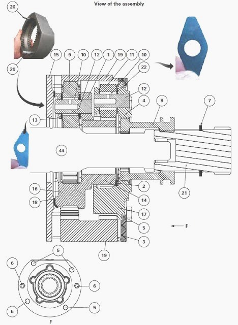
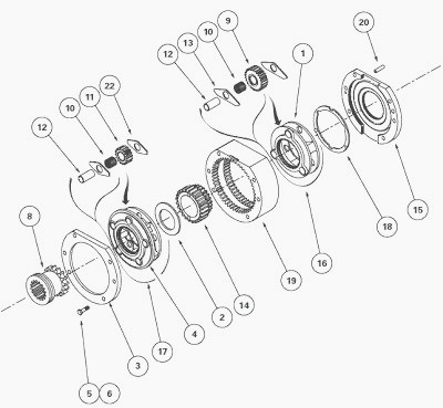
(1) Input planet carrier (2) Friction washer (3) Cover plate (4) Output
planet carrier (5) Screw (6) M8 screw (7) Circlip (8) Coupler (9) Input
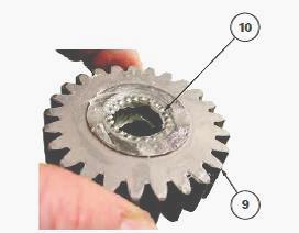
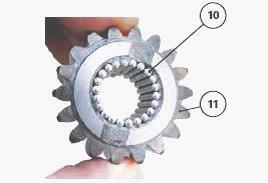
planet gears (10) Needle rollers (11) Output planet gears (12) Pins (13)
Input planet gear plates (14) Sun gear (15) Stop plate (16) Input
epicyclic gear train (17) Output epicyclic gear train (18) Folded
friction washer (19) Ring gear unit (20) Dowels (21) Link shaft (22)
Output planet gear plates (44) GBA-20 gearbox output shaft
Kinematics and operation
Kinematics of the input epicyclic gear train
- Ring gear unit (19) blocked.
- Drive input via output shaft (44) of the GBA20 gearbox.
- Drive output via planet carrier (1).
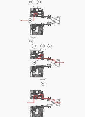
Kinematics of the output epicyclic gear train
- Ring gear unit (19) blocked.
- Drive continuity via sun gear (14).
- Drive output to rear axle via planet carrier (4).
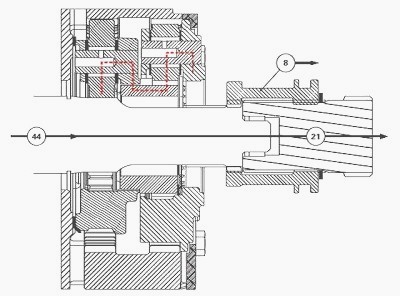
- The sun gear (14) is secured by splines on the planet carrier (1).
The coupler (8) is secured by splines on the link shaft (21). Movement
of lever A to Snail position moves the coupler (8) forwards and engages
it with the planet
carrier (4) via its external teeth. The speed of the link shaft (21) is
1/14 that of the gearbox output shaft (44).
When the coupler (8) is
engaged in the output planet
carrier (4), the needle roller bearing (1) allows the link shaft (21) to
turn at a different speed to that of the output shaft (44).
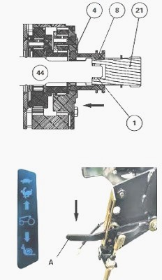
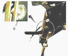
When the super creeper range is selected, the Snail indicator light on
the instrument panel comes on. The electrical signal corresponding to
selection of the super
creeper range is transmitted via switch C, which is fitted on the
control unit.
In normal gears, the gearbox output shaft (44) is engaged with the link
shaft (21) when the coupler (8) is moved backwards, thus ensuring direct
drive.
Epicyclic gear trains repair
Split the MF 5470, 5475 tractor between the gearbox and the rear axle.
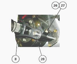
Remove: the counter-nut (26), the adjustable lock (27), the fork (28)
and the coupler (8). Remove the screws (5).
Separate the super creeper unit from the Massey Ferguson 5470, 5475
gearbox. Place it on a workbench.
Remove the M8 screws (6). Remove: the cover plate (3), the output planet
carrier (4), the sun gear (14), the input planet carrier (1).
Recover the folded friction washer (18). Separate the stop plate (15)
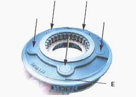
from the ring gear unit (19).
The dowels (20) are force fitted onto the ring gear unit (19). Check and
clean all components. Replace those that are defective.
Check that all dowels (20) are present on the ring gear unit (19).
Assemble the stop plate (15) on the ring gear unit.
Lightly smear the folded friction washer (18) with miscible grease.
Position the folds of the friction washer face-to-face with the notches.
Install the friction washer up against the input planet carrier (1).
Install: the input planet carrier (1), the sun gear (14), the output
planet carrier (4), the cover plate (3).
Install and tighten the M8 screws (6) to a torque of 25 - 35 Nm.
Assemble the super creeper unit on the gearbox.
Install and tighten the screws (5) to a torque of 33.8 - 51.5 Nm.
Install: the fork (28) and the coupler (8), the adjustable lock (27),
the counter-nut (26).
Adjust the fork locking mechanism (27). Reconnect the MF 5470, 5475
tractor between the gearbox and the rear axle.
Disassembling and reassembling the planet carriers
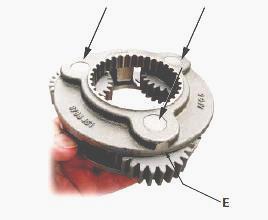
Position the input planet carrier (1) under a press and on top of a
plate pierced with a hole to allow removal of the pins (12).
Drive out a pin using the press and a makeshift drift (D 12 mm) in the
direction of the arrows.
The pin is force fitted into part E of the planet carrier.
Remove the planet gear (9) and plates (13) from the planet carrier.
Recover the needle rollers (10).
Repeat operations to disassemble the other two planet gears. Clean and
check all components. Replace those that are defective.
Lightly smear the bore of the planet gear (9) with miscible grease.
Arrange the needle rollers (10) on the grease cartridge, taking care not
to omit any.
Repeat to prepare the other two planet gears.
Install a planet gear pin
Place the input planet carrier (1) on a press.
Slide a planet gear (9), fitted with its needle rollers (10) and plates,
(13) into the planet carrier.
Line up the planet gear and plates with the planet carrier pin hole
(12).
Check that the axial channel and radial hole of the pin are not blocked.
Turn the axial channel inlet of the pin (12) as shown in figure.
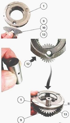
Slide the pin partly into: the input planet carrier (1), the planet gear
(9), the plates (13).
Turn the pin. Turn the radial hole R as shown.
Install the pin (12) so that its blunt end is almost level with surface
F of the planet carrier.
Check manually on the planet gear (9): the presence of slight axial
clearance, the free rotation of the planet gear.
Repeat operations to fit the other two pins.
Disassembling the output planet carrier
Position the output planet carrier (4) under a press and on top of a
plate pierced with a hole to allow removal of the pins (12).
Drive out a pin using the press and a makeshift drift (D 12 mm) in the
direction of the arrows.
The pin is force fitted into part E of the planet carrier.
Remove the planet gear (11) and plates (22) from the planet carrier.
Recover the needle rollers (10). Repeat to disassemble the other four
planet gears.
Clean and check all components. Replace those that are defective.
Lightly smear the bore of the planet gear (11) with miscible grease.
Arrange the needle rollers (10) on the grease cartridge, taking care not
to omit any.
Repeat steps to prepare the other four planet gears.
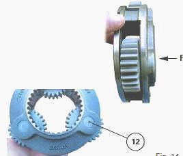
Install a planet gear pin
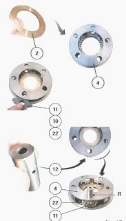
Place the output planet carrier (4) under a press. Install the friction
washer (2) into the base of the planet carrier (4).
Slide a planet gear (11), fitted with its needle rollers (10) and plates
(22), into the planet carrier.
Line up the planet gear and plates with the planet carrier pin hole
(12).
Check that the axial channel and radial hole of the pin are not blocked.
Turn the axial channel inlet of the pin (12) as shown.
Slide the pin partly into: the output planet carrier (4), the planet gear (11), the plates (22). Turn the pin. Turn the radial hole R as shown in pic.
Install the pin (12) so that its blunt end is almost level with surface
of the planet carrier.
Check manually on the planet gear (11): the presence of slight axial
clearance, the free rotation of the planet gear. Repeat to fit the other
four pins.
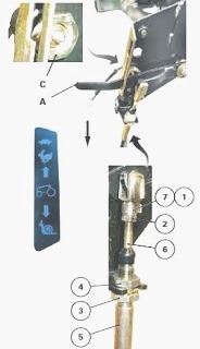
Adjusting the control
Cab side
Place control lever A in the Snail position.
The control lever may be located in two positions on the right-hand
console, depending on whether or not an auto-hitch is fitted.
Screw the clevis (1) level with the end of the threaded part of the
cable.
Install the clevis (1) onto lever A with the clip (7). Tighten the nut.
Screw the nut (3) onto the sheath end (5). Install the sheath end and
the lock washer onto the support.
Tighten the nut (4). After tightening, check that the cable is not
pinched.
Gearbox side
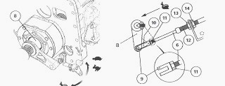
Place rod "B" in the "super creeper" position (Snail position, with the
reducer dog (8) engaged towards the front, fork locked).
Screw the clevis (9) level with the end of the threaded part of the
cable (6). Install the clevis (9) to rod B using the clip (10).
Tighten the nut (11). Adjust the stop (12) with the nut (13), making sure that rod B is still firmly locked. Tighten the nut (14). After tightening, check that the cable is not pinched. Check that the control is locked in the "direct drive" position.
________________________________________________________________________________
________________________________________________________________________________________
 SPECS
SPECS LOADERS
 MAINTENANCE
 PROBLEMS
________________________________________________________________________________________
 MF 1523
 MF 1531
 MF 135
 MF 1547
 MF 1635
________________________________________________________________________________________
________________________________________________________________________________________
 231
231 231S
231S 235
235 240
240 241
241________________________________________________________________________________________
 255
255 265
265 274
274 285
285 375
375________________________________________________________________________________________
________________________________________________________________________________________
 916X Loader
 921X Loader
 926X Loader
 931X Loader
 936X Loader
________________________________________________________________________________________
 941X Loader
 946X Loader
 951X Loader
 956X Loader
 988 Loader
________________________________________________________________________________________
 1655
1655 GS1705
 1742
1742 2635
2635 4608
4608________________________________________________________________________________________
 1080
1080 1100
1100 2615
2615 3050
3050 3060
3060________________________________________________________________________________________
 4708
4708 5455
5455 5450
5450 5610
5610 5613
5613________________________________________________________________________________________
 DL95 Loader
 DL100 Loader
 DL120 Loader
 DL125 Loader
 DL130 Loader
________________________________________________________________________________________
 DL135 Loader
 DL250 Loader
 DL260 Loader
 L90 Loader
 L100 Loader
________________________________________________________________________________________
 6499
6499 7480
7480 7618
7618 7726
7726 1533
1533________________________________________________________________________________________
 2604H
2604H 2607H
2607H 4455
4455 4610M
4610M 4710
4710________________________________________________________________________________________
 L105E Loader
 L210 Loader
 1014 Loader
 1016 Loader
 1462 Loader
________________________________________________________________________________________
 1525 Loader
 1530 Loader
 232 Loader
 838 Loader
 848 Loader
________________________________________________________________________________________
 5712SL
 6713
6713 6715S
6715S 7475
7475 7615
7615________________________________________________________________________________________
 7716
7716 7724
7724 8240
8240 8650
8650 8732
8732________________________________________________________________________________________
 246 Loader
 1036 Loader
 1038 Loader
 1080 Loader
 856 Loader