
________________________________________________________________________________
MF 6280, 6290, 5435, 5440 tractor hydraulic system - Open centre
Massey Ferguson 5400, 6200 series tractors open centre hydraulic system
(57 l/min) comprises two separate systems.
These two systems are supplied by a two-stage gear pump fitted on the
internal face of the right-hand hydraulic cover plate. The pump sucks
transmission oil from the common tank formed by the centre housing and
the gearbox through a 150 micron filter, also fitted on the right-hand
coverplate.
A 15 micron main filter and a blockage indicator are fitted to the low
flow rate system upstream of the Orbitrol steering spool valve. The
hydraulic pump is driven by the ring gear of the PTO clutch unit.
Low-pressure system, low flow rate
The first stage of the pump supplies the Massey Ferguson 6280, 6290
hydrostatic steering where pressure can reach 170 bar.
Hydraulic flow
After supplying the Orbitrol steering spool valve as required, the oil
is directed to the left-hand cover plate attached to the centre housing.
This cover plate performs
several low-pressure functions.
It ensures:
- operating pressure for the transmission components via a 17
bar valve fitted downstream from the Orbitrol unit;
- cooling and lubrication of the gearbox and connected components,
- pressure for the brake master cylinders (excluding MERITOR master
cylinders).
MF 5435, 5440 transmission components
The 17-bar system supplies, in parallel, the various transmission
functions via solenoid valves flanged on the reverse shuttle clutch
unit, on the Speedshift control
and in the main channel of the right-hand cover plate.
None of these
functions has priority and they may be activated simultaneously. Some of
the solenoid valves
(4WD, power take-off, Speedshift and reverse shuttle (proportional
solenoid valves)) are linked to the tractor's electronic system.
The functions supplied by the low flow rate system are as follows:
- the hydrostatic steering,
- the Hare / Tortoise range shifting (Hi / Lo),
- the differential lock (front and rear),
- the 4WD clutch,
- the Speedshift,
- The clutch control valve,
- the clutch unit of the reverse shuttle,
- the power take-off system,
- clutch,
- brake,
- front PTO (depending on option).
Cooling and lubrication
When the various components of the transmission are supplied, the
left-hand cover plate directs oil towards the cooler when it is hot, or
directly towards to the
gearbox and PTO when it is cold.
The lubrication pressure is maintained
by a valve set to 1.5 bar and fitted on the front left-hand side of the
gearbox.
Pressure for brake master cylinder - Only unassisted master cylinders
receive pressure from the hose connected upstream to the 1.5 bar valve.
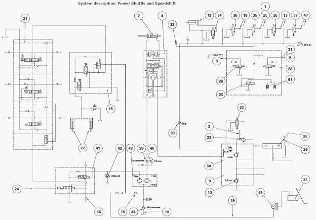
Layout of the main Speedshift and Power Shuttle system components
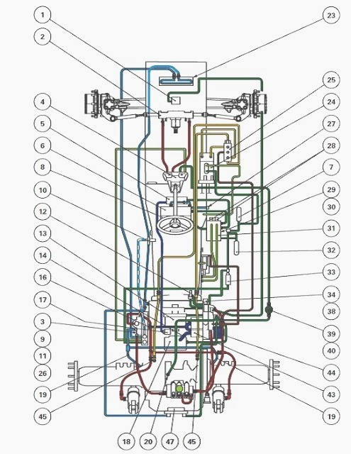
(1) Front differential lock (2) Steering ram (3) Pressure connector (4)
Hydrostatic spool valve (Orbitrol)
(5) Forward clutch (reverse shuttle) (6) Reverse clutch (reverse
shuttle) (7) Accumulator (assisted master cylinders) (8) Speedshift
mechanism (9) Left-hand cover
plate (10) 1.5 bar valve (11) Temperature switch
(12) Hare/Tortoise mechanism (13) PTO clutch (14) Pump suction pipe (16)
Restrictor (17) Suction strainer (Reverse shuttle clutch lubrication
pump) (18) 4WD
clutch (19) Brake lubrication pipes (20) Rear differential lock (23) Oil
cooler (24) Brake master cylinders (25) FTE valve
(26) Bleed connector (27) Diagnostics connector (reverse shuttle
lubrication)
(28) Proportional solenoid valves (reverse shuttle) (30) Speedshift
solenoid valve (31) Gearbox control unit (32)Accumulator (33) 60 micron
filter (34) Hare/Tortoise
solenoid valve (35) Differential lock solenoid valve (36) PTO solenoid
valve (37) PTO brake solenoid valve (38) 4WD solenoid valve (39) 15
micron filters (40)
Blockage indicator (43) Two-stage hydraulic pump (44) 150 micron suction
filter (45) Left and right brakes (47) PTO brake
Layout of the main Speedshift and mechanical reverse shuttle system
components
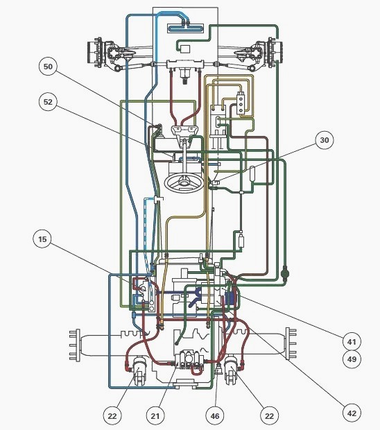
(15) Linkage valve (21) Auxiliary spool valves (22) Lift rams (41)
Trailer brake valve (spool valve) (42) High pressure safety valve (46)
Trailer brake connector (49)
1.5 bar valve (clutch(es) lubrication system) (50) Hydraulically
controlled clutch master cylinder (61) Speedshift mechanism
(62) Speedshift solenoid valve
Massey Ferguson 5435, 5440 High-pressure hydraulic system, high flow
rate
The second stage of the pump supplies, in the following order:
- the trailer brake spool valve, which is priority (if fitted);
- the auxiliary spool valves;
- the linkage valve.
The oil not used by the trailer brake spool valve supplies the auxiliary spool valves fitted to the rear of the linkage cover plate.
Starting at the auxiliary spool valves, a line supplies the linkage spool valve located on the left-hand side cover plate.
The excess flow rate from the spool valves returns to the pump suction manifold via a restrictor (16) without passing through the 150 micron filter.
A safety
valve, set to 200 bar, is fitted in the discharge channel on the
right-hand cover plate to protect
the high pressure system.
Mechanical reverse shuttle and Speedshift diagram
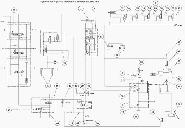
(1) Front differential lock (2) Steering ram (3) Pressure connector
(approximately 5 bar) (4) Hydrostatic spool valve (Orbitrol) (5) Forward
clutch (Power Shuttle) (6)
Reverse clutch (Power Shuttle) (8) Speedshift mechanism (9) Gearbox (10)
1.5 bar valve (11) Temperature switch
(12) Hare/Tortoise mechanism (13) PTO clutch (14) Pump suction pipe (15)
Linkage spool valve (16) Restrictor (18) 4WD clutch (19) Brake
lubrication pipes (20)
Rear differential lock (21) Auxiliary spool valves (22) Lift rams (23)
Oil cooler (24) Brake master cylinders
(25) Tank (excluding MERITOR master cylinders) (26) Connector to assist
brake bleeding (28) Proportional solenoid valves (Power Shuttle) (31)
Clutch unit
(reverse shuttle) (32) Accumulator
(33) 60 micron filter (34) Hare/Tortoise solenoid valve (35)
Differential lock solenoid valve (36) PTO solenoid valve (37) PTO brake
solenoid valve (38) 4WD
solenoid valve (39) 15 micron filters
(40) Blockage indicator (41) Trailer brake valve (spool valve) (42) High
pressure safety valve (43) Two-stage hydraulic pump (44) 150 micron
suction filter (45) Left
and right brakes (46) Trailer brake connector (47) PTO brake (48) Valve
(reverse shuttle, reverse clutch, opening at 13 bar) (49) 1.5 bar valve
(clutch(es) lubrication
system) (50) Left-hand hydraulic cover plate
(61) Speedshift mechanism (62) Speedshift solenoid valve (63) Front PTO
solenoid valve (64) Clutch thrust bearing (65) Assisted clutch master
cylinder (66) Non-return valve (clutch control) (67) Accumulator
Reverse shuttle
Lubrication
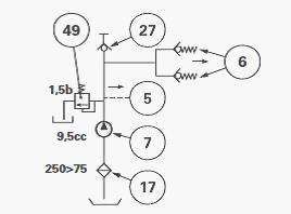
(5) To forward clutch lubrication (6) To reverse clutch lubrication (7)
Lubrication pump (17) Suction strainer (27) Diagnostics connector (49)
1.5 bar valve
MF 6280, 6290 Power Shuttle and Speedshift diagram
(1) Front differential lock (2) Steering ram (3) Pressure connector
(approximately 5 bar) (4) Hydrostatic spool valve (Orbitrol) (5) Forward
clutch (Power Shuttle) (6)
Reverse clutch (Power Shuttle) (8) Speedshift mechanism (9) Gearbox (10)
1.5 bar valve (11) Temperature switch
(12) Hare/Tortoise mechanism (13) PTO clutch (14) Pump suction pipe (15)
Linkage spool valve (16) Restrictor (18) 4WD clutch (19) Brake
lubrication pipes (20)
Rear differential lock (21) Auxiliary spool valves (22) Lift rams (23)
Oil cooler (24) Brake master cylinders (25) Tank (excluding MERITOR
master cylinders) (26)
Connector to assist brake bleeding
(28) Proportional solenoid valves (Power Shuttle) (31) Clutch unit
(reverse shuttle) (32) Accumulator (33) 60 micron filter (34)
Hare/Tortoise solenoid valve (35)
Differential lock solenoid valve
(36) PTO solenoid valve (37) PTO brake solenoid valve (38) 4WD solenoid
valve (39) 15 micron filters (40) Blockage indicator (41) Trailer brake
valve (spool valve)
(42) High pressure safety valve
(43) Two-stage hydraulic pump (44) 150 micron suction filter (45) Left
and right brakes (46) Trailer brake connector (47) PTO brake
(48) Valve (reverse shuttle, reverse clutch, opening at 13 bar) (49) 1.5
bar valve (clutch(es) lubrication system) (50) Left-hand hydraulic cover
plate (61) Speedshift
mechanism (62) Speedshift solenoid valve (63) Front PTO solenoid valve
________________________________________________________________________________
________________________________________________________________________________________
 SPECS
SPECS LOADERS
 MAINTENANCE
 PROBLEMS
________________________________________________________________________________________
 MF 1523
 MF 1531
 MF 135
 MF 1547
 MF 1635
________________________________________________________________________________________
________________________________________________________________________________________
 231
231 231S
231S 235
235 240
240 241
241________________________________________________________________________________________
 255
255 265
265 274
274 285
285 375
375________________________________________________________________________________________
________________________________________________________________________________________
 916X Loader
 921X Loader
 926X Loader
 931X Loader
 936X Loader
________________________________________________________________________________________
 941X Loader
 946X Loader
 951X Loader
 956X Loader
 988 Loader
________________________________________________________________________________________
 1655
1655 GS1705
 1742
1742 2635
2635 4608
4608________________________________________________________________________________________
 1080
1080 1100
1100 2615
2615 3050
3050 3060
3060________________________________________________________________________________________
 4708
4708 5455
5455 5450
5450 5610
5610 5613
5613________________________________________________________________________________________
 DL95 Loader
 DL100 Loader
 DL120 Loader
 DL125 Loader
 DL130 Loader
________________________________________________________________________________________
 DL135 Loader
 DL250 Loader
 DL260 Loader
 L90 Loader
 L100 Loader
________________________________________________________________________________________
 6499
6499 7480
7480 7618
7618 7726
7726 1533
1533________________________________________________________________________________________
 2604H
2604H 2607H
2607H 4455
4455 4610M
4610M 4710
4710________________________________________________________________________________________
 L105E Loader
 L210 Loader
 1014 Loader
 1016 Loader
 1462 Loader
________________________________________________________________________________________
 1525 Loader
 1530 Loader
 232 Loader
 838 Loader
 848 Loader
________________________________________________________________________________________
 5712SL
 6713
6713 6715S
6715S 7475
7475 7615
7615________________________________________________________________________________________
 7716
7716 7724
7724 8240
8240 8650
8650 8732
8732________________________________________________________________________________________
 246 Loader
 1036 Loader
 1038 Loader
 1080 Loader
 856 Loader