
________________________________________________________________________________
Massey Ferguson 6460, 6465 hydraulic system - Block valves for steering and low pressure
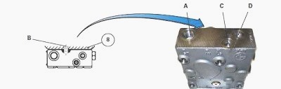
Valves block
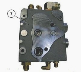
The single valves block (7), Installed to the right-hand hydraulic cover
plate (8), is fitted to 40 kph tractors without trailer braking. Valves
block has two spools and
receives the flow rate from the variable displacement pump.
It ensures
priority for the Massey Ferguson 6465, 6460 steering system and the 17
or 21 bar low
pressure system. The oil is then directed to the auxiliary spool valves
and linkage spool valve.
This section primarily describes the single block valves (7) without
trailer braking.
The hydraulic unit with two priority blocks and with 40
kph trailer braking or trailer
braking for MF 6460, 6465 tractors fitted with a high-pressure braking
unit is described in its own section.
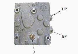
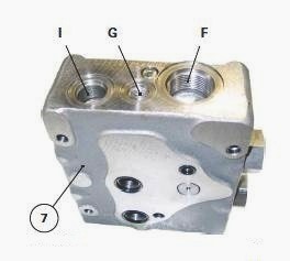
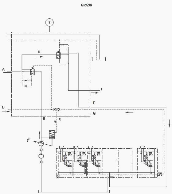
Identification of 110 l/min or 150 l/min Load Sensing (LS) ports
on the single valves block
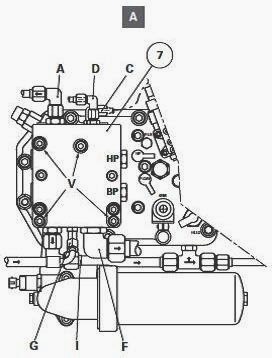
A - Orbitrol supply, B - High pressure (HP) supply from variable
displacement pump (drilled port on the mating face of priority block and
cover plate), C - LS pilot
flow to the variable displacement pump hydraulic regulator, D - LS pilot
flow from the Orbitrol, F - Spool valve (auxiliary and linkage) supply,
G - LS pilot flow from
spool valves (auxiliary and linkage), H - Internal channel, I - 17 or 21
bar outlet, J - Plug, HP - High-pressure (HP) spool, BP - Low-pressure
(BP) spool
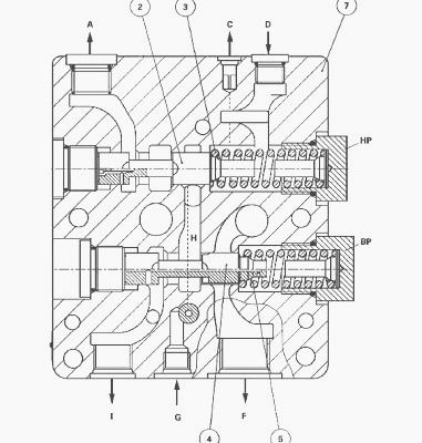
1st position - Steering
The spool (2) moves to the left under the action of spring (3).
The flow
coming from the variable displacement pump via channel B is by priority
directed towards the
Orbitrol spool valve via channel A.
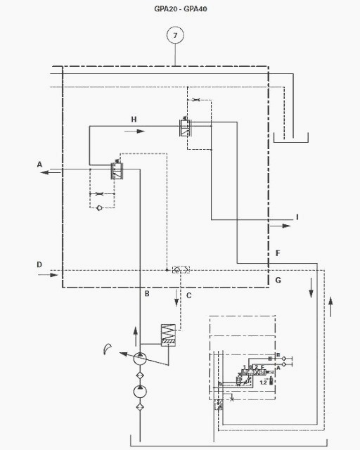
Steering at neutral:
The steering spool valve (Orbitrol) is in closed position. The pump
pressure moves spool (2) to the right and the flow is directed into
channel H.
Steering activated:
A pilot flow pressure from the Orbitrol arrives at port D and pushes the
spool (2) to the left, allowing the flow to enter port A and supply the
Orbitrol.
A flow of approximately 0.5 l/min is directed through port A towards port D via a drilled hole and restrictor in spool (2). This flow rate creates pressure of approximately 6 bar at port D.
The LS line directs this pressure to the variable
displacement pump regulator which is adjusted to 22 bar in order to
obtain a standby pressure of 28 bar.
2nd position - 17 or 21 bar pressure control valve
The spool (4) moves to the left under the action of the spring (5),
allowing the flow from channel H to be directed into port I (17 or 21
bar low pressure).
As soon as the pressure in this port reaches 17 or 21 bar, the spool reaches equilibrium thus allowing the low pressure to be maintained and the flow to be directed towards port F (linkage and auxiliary).
When the linkage and auxiliary spool valves
are used, an LS pilot flow pressure is sent to the block via port G to
join the LS line at port C.
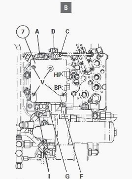
Checking after servicing
If the single priority block (7) had to be replaced:
- Lightly smear the thread of screws V with Loctite 542 or equivalent.
Tighten these screws to a torque of 25 - 35 Nm.
- Carry out hydraulic tests.
Check the tightness of the unions and "O" rings fitted between the
single priority block and the right-hand hydraulic cover plate. Carry
out a road test.
MF 6465, 6460 hydraulic pump drive bearing - Repair operation
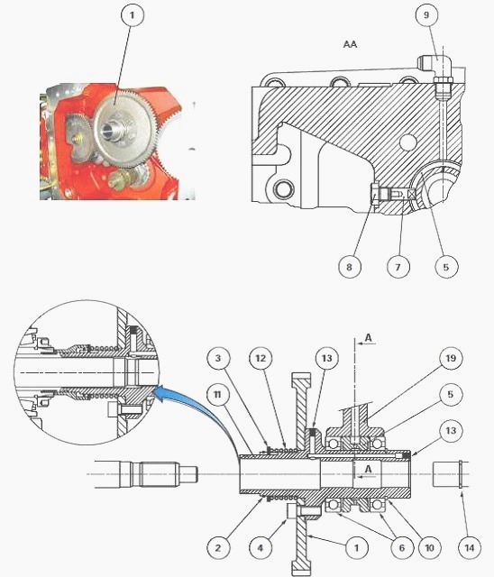
Disconnect the Massey Ferguson 6460, 6465 tractor between the gearbox
and the intermediate housing.
Remove the components of the creeper unit (if fitted) that might hinder
the removal of the hydraulic pump drive gear.
Remove:
- the stop ring (2)
- the tab washer (3)
- the spring (12)
- the drive gear (1) fixed to the bearing (11)
Removing the bearing
Unscrew the plug (8).
Pull the pin (7) using a threaded rod, such as to free the spacer (5);
Pull the bearing (11) such as to remove it from its bore through the
front of the intermediate housing.
Reinstall the bearing
Check neither the channel nor drilled hole in the spacer (5) is blocked;
Check the circlip (14) is present on the upper PTO shaft. Reinstall the
bearing (11).
Position the groove of spacer (5) along the axis of the port provided
for plug (8).
Slide the pin (7) into its bore, inserting its flat sections into the
groove of the spacer (5). Tighten the plug (8).
Ensure that the bearing is correctly held by the pin (7) and that it
rotates freely. Reinstall the gear (1).
Lightly smear the thread of the screws (4) with Loctite 242 or
equivalent. Tighten these screws to 72-96 Nm.
Reinstall:
- the spring (12)
- the tab washer (3)
- the stop ring (2)
Disassembling the hydraulic pump drive bearing
Remove the circlip (10). Extract the rollers (6) from the bearing.
Remove the spacer (5).
Reassembling the bearing
Clean and check all components. Replace those that are defective. Using a press and a suitable fixture, insert the rollers (6), separated by the spacer (5), into the bearing (11).
The force of the press must be applied to the internal ring of the rollers. Reinstall the circlip (10).
The rollers of the hydraulic pump drive
bearing
(11) are lubricated by an oil flow from the right-hand hydraulic cover
plate via the union (9). Install and adjust the creeper unit components.
Reconnect the tractor between the gearbox and the intermediate housing. Carry out a road test of all controls. Check the tightness of the mating faces and hydraulic unions.
________________________________________________________________________________
________________________________________________________________________________________
 SPECS
SPECS LOADERS
 MAINTENANCE
 PROBLEMS
________________________________________________________________________________________
 MF 1523
 MF 1531
 MF 135
 MF 1547
 MF 1635
________________________________________________________________________________________
________________________________________________________________________________________
 231
231 231S
231S 235
235 240
240 241
241________________________________________________________________________________________
 255
255 265
265 274
274 285
285 375
375________________________________________________________________________________________
________________________________________________________________________________________
 916X Loader
 921X Loader
 926X Loader
 931X Loader
 936X Loader
________________________________________________________________________________________
 941X Loader
 946X Loader
 951X Loader
 956X Loader
 988 Loader
________________________________________________________________________________________
 1655
1655 GS1705
 1742
1742 2635
2635 4608
4608________________________________________________________________________________________
 1080
1080 1100
1100 2615
2615 3050
3050 3060
3060________________________________________________________________________________________
 4708
4708 5455
5455 5450
5450 5610
5610 5613
5613________________________________________________________________________________________
 DL95 Loader
 DL100 Loader
 DL120 Loader
 DL125 Loader
 DL130 Loader
________________________________________________________________________________________
 DL135 Loader
 DL250 Loader
 DL260 Loader
 L90 Loader
 L100 Loader
________________________________________________________________________________________
 6499
6499 7480
7480 7618
7618 7726
7726 1533
1533________________________________________________________________________________________
 2604H
2604H 2607H
2607H 4455
4455 4610M
4610M 4710
4710________________________________________________________________________________________
 L105E Loader
 L210 Loader
 1014 Loader
 1016 Loader
 1462 Loader
________________________________________________________________________________________
 1525 Loader
 1530 Loader
 232 Loader
 838 Loader
 848 Loader
________________________________________________________________________________________
 5712SL
 6713
6713 6715S
6715S 7475
7475 7615
7615________________________________________________________________________________________
 7716
7716 7724
7724 8240
8240 8650
8650 8732
8732________________________________________________________________________________________
 246 Loader
 1036 Loader
 1038 Loader
 1080 Loader
 856 Loader