
________________________________________________________________________________
Massey Ferguson 6455, 6470 hydraulic low pressure valve - Open Centre
The Massey Ferguson 6470, 6455 low pressure valve (17 bar) (2) is
screwed onto the left-hand hydraulic cover.
It performs the following functions:
- it supplies oil and maintains pressure in the 17 bar low pressure
circuit
- it supplies the cooling system (5 bar) and lubricating system (1.5
bar).

(2) 17 bar valve (3) O’ring (4) Plug (5) Spring (6) Ball (7) Spool (8)
Shim(s) (9) Spring (10) O’ring (11) Seal (12) Plug (13) Valve sleeve
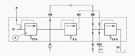
Identification of ports
G - Brake master cylinder booster (excluding Meritor type), O - Valve
supply via the steering spool valve return (Orbitrol), P - Outlet to low
pressure parts, R1 -
Return (1.5 bar valve), BV - Lubrication to 1.5 bar valve (cold oil), RR
- Lubrication - cooling system return, VR - Lubrication to cooling
system, PDF - Lubricating
line to rear PTO
Description of the MF 6455, 6470 17 bar low pressure valve
As soon as the engine is started, the return oil from the steering unit
(Orbitrol) enters port O and exits by port P of the left-hand cover.
It is directed towards the low pressure circuit of the right-hand
hydraulic cover in order to supply:
- power shuttle (if fitted)
- dynashift unit
- changing between Hare / Tortoise range
- 4WD clutch
- front and rear differential locks
- rear PTO brake and clutch
- front power take off (if fitted).
A back pressure is generated in the low pressure circuit, forcing the
ball from its seating and thereby compressing the spring. The oil passes
into the rear of the
spool, creating a pressure which progressively moves it downwards by
compressing the spring which thrusts against the shims.
When one of the low pressure functions is activated, the momentary drop in pressure returns the ball to its seating through the action of the spring.
The oil contained
in the chamber at the front of the plug flows through a drain port
located at the end of the spool. Leaks return to the housing via port R
in the cover.
MF 6470, 6455 low pressure valve (17 bar) repair
It is not necessary to remove the left-hand hydraulic cover to carry out
work on the valve.
Removal
Remove any parts around the valve that may obstruct work.
Remove and separate the valve (2) from the left-hand hydraulic cover.
Install
Check the condition of the O'ring (10) and replace if necessary.
Screw the valve back onto the cover and tighten to 40 - 55 Nm.
Disassembly

The valve comprises several hydraulic parts (spool, springs and ball)
which cannot be replaced separately. Remove the O'ring (10).
Tighten the hexagonal head of the valve in a vice with protective jaws.
Gradually unscrew the plug (12) and discard the O'ring (11).
Recover: spring (9), shim(s) (8).
Gradually unscrew the plug (4) and discard the O'ring (3).
Recover: spring (5), ball (6).
Remove the spool (7) by carefully tapping the shaft (13) against a
wooden shim.
Reassembly
The hydraulic parts must be reassembled on a clean work surface clear of
filings and dirt.
Check:
- the condition of the springs and O’rings
- the absence of scratches or seizing on the moving parts of the valve
- the sliding of the spool in its sleeve
- the cleanliness of the ports.
Conclusion - If the valve is defective, replace it. If not, reassemble
it by carrying out the disassembly operations in reverse order.
Adjusting the Low pressure valve (17 bar)
- It is not necessary to remove the left-hand hydraulic cover to adjust
the valve.
- When the valve is removed, it can be adjusted inserting shims (8)
between the spool (7) and the spring (9).
Operation of the cooling system
The pressure acting on the back of the spool pushes it towards the
bottom of the valve, pressing in the spring. It then allows oil to pas
to port VR and the cooler.
When it leaves the cooler, the oil is directed to the Massey Ferguson
6455, 6470 transmission lubricating system via the 1.5 bar valve.
5 bar valve
When the oil is cold, the 5 bar valve opens partially. It then allows
some oil to pass directly to port BV of the left-hand cover, and to
supply the transmission
lubricating system, without really entering the cooler.
Assembling the Low pressure valve (5 bar)
It is not necessary to remove the left-hand hydraulic cover to carry out
work on the valve. Remove the pipe and union.
Place the valve, spring and threaded ring in the cover.
Compress the spring, tightening the threaded bush until it reaches a
“hard point” (the bush has reached the cover shoulder).
After assembly, check that free movement of the valve and the
compression of the spring, entering a screwdriver through the port
provided for screwing in the
temperature switch, located on the lower part of the cover.
Description of the 1.5 bar lubricating valve
The 1.5 bar valve is hidden behind the fuel tank, and is located at the
front left-hand side of the gearbox.
It controls the oil coming from the cooling circuit, and maintains a
lubricating pressure of approximately 1.5 bar in the circuit, due to the
valve setting. If the pressure
exceeds 1.5 bar, the spring compresses, the valve moves and oil flows to
the return R1.
When the requirements of the low pressure circuit are met, oil is
channelled towards the booster port of the brake master cylinders in
order to ensure a constant oil
level.
Considering the available hydraulic options, other assemblies can
be carried out on the union. Example: Front PTO - Meritor brake master
cylinders.
1.5 bar valve repair


Removal
Remove the part(s) that may obstruct work on the valve (1).
Mark and disconnect the pipes (5) (6), hoses (7) (8) and unions (2) (3)
(4).
Remove the housing valve from the MF 6455, 6470 gearbox.
Refitting
Replace the O’rings if necessary.
Reinstall the valve, unions, hoses and pipes.
Replace any part(s) removed at operation.
Disassembly and Reassembly
Take off circlip (5). Remove the bush (2), spring (3) and valve (4) from
the valve body (6).
The valve (1) consists of several hydraulic parts (valve, spring) listed
in the spare parts catalogue.
Check that the hydraulic parts are clean.
Reassemble the valve, carrying out operation in reverse order.
Manually check the free movement of the valve.
________________________________________________________________________________
________________________________________________________________________________________
 SPECS
SPECS LOADERS
 MAINTENANCE
 PROBLEMS
________________________________________________________________________________________
 MF 1523
 MF 1531
 MF 135
 MF 1547
 MF 1635
________________________________________________________________________________________
________________________________________________________________________________________
 231
231 231S
231S 235
235 240
240 241
241________________________________________________________________________________________
 255
255 265
265 274
274 285
285 375
375________________________________________________________________________________________
________________________________________________________________________________________
 916X Loader
 921X Loader
 926X Loader
 931X Loader
 936X Loader
________________________________________________________________________________________
 941X Loader
 946X Loader
 951X Loader
 956X Loader
 988 Loader
________________________________________________________________________________________
 1655
1655 GS1705
 1742
1742 2635
2635 4608
4608________________________________________________________________________________________
 1080
1080 1100
1100 2615
2615 3050
3050 3060
3060________________________________________________________________________________________
 4708
4708 5455
5455 5450
5450 5610
5610 5613
5613________________________________________________________________________________________
 DL95 Loader
 DL100 Loader
 DL120 Loader
 DL125 Loader
 DL130 Loader
________________________________________________________________________________________
 DL135 Loader
 DL250 Loader
 DL260 Loader
 L90 Loader
 L100 Loader
________________________________________________________________________________________
 6499
6499 7480
7480 7618
7618 7726
7726 1533
1533________________________________________________________________________________________
 2604H
2604H 2607H
2607H 4455
4455 4610M
4610M 4710
4710________________________________________________________________________________________
 L105E Loader
 L210 Loader
 1014 Loader
 1016 Loader
 1462 Loader
________________________________________________________________________________________
 1525 Loader
 1530 Loader
 232 Loader
 838 Loader
 848 Loader
________________________________________________________________________________________
 5712SL
 6713
6713 6715S
6715S 7475
7475 7615
7615________________________________________________________________________________________
 7716
7716 7724
7724 8240
8240 8650
8650 8732
8732________________________________________________________________________________________
 246 Loader
 1036 Loader
 1038 Loader
 1080 Loader
 856 Loader