
________________________________________________________________________________
Massey Ferguson 6614, 6615 tractor electrohydraulic auxiliary spool valves
The Bosch/Rexroth SB23 LS spool valves controlling supply to the Massey
Ferguson 6614, 6615 hydraulic couplers are comprised of: hydraulic and
electrohydraulic part.
An electrohydraulic part comprising:
- an ON/OFF solenoid valve and a 3-way pressure relief valve located on
the end plate of the spool valve block,
- a pilot valve fitted in the electrohydraulic unit.
This section shall concern the hydraulic part only. The Bosch/Rexroth
SB23 LS electric hydraulic control spool valves are supplied by high
flow rate, high pressure
oil from the priority blocks.
When no functions are being activated, the entire flow rate is directed towards the spool valves. When certain functions are being supplied, the excess flow then remains available to the auxiliary spool valves.
The adjustment of the flow rate, expressed as a percentage, may be displayed on the onboard computer (Datatronic) by the operator.
The MF 6614, 6615 tractor electric hydraulic spool valves controlled by a Joystick are fitted with a floating Kick-out position (automatic return to neutral).
The main spool of the spool valve directs oil towards the outlet ports A or B. Each outlet port is linked to the LS pilot line of the variable displacement pump regulating valve via the priority block(s).
The spool valves consist of both electronic and hydraulic components,
the latter containing
spools and valves. Some elements cannot be repaired as spare parts.
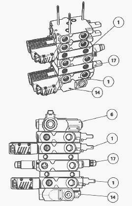
Different types of spool valve block components
A spool valve block can consist of three, four or five of the following
components. It can combine components of similar type of or different
types.
Component a - Electrohydraulic component (Joystick)
Component b - Electrohydraulic component (Dual Control)
Component c - Mechanically controlled component.

(1) Auxiliary spool valves (6) End plate (14) Inlet block (17) Lift
control spool valve (18) ON/OFF solenoid valve (19) Electronic units
Operation of the pressure relief valve and electrohydraulic unit
When the ON/OFF solenoid valve located on end plate is open, the flow
from the pump is directed to the 3-way pressure relief valve.
The 3-way pressure relief valve supplies the pilot valve with a pressure
of 21 - 24 bar via a pressure balancing valve.
The pilot valve receives a signal from the digital device and moves the
main spool of the auxiliary electric hydraulic spool valve according to
the information
received from the Joystick.
The digital device is informed of the position of the main spool by a
displacement sensor.
The pilot valve and the digital device are housed in the unit fixed
below the spool valve.
The pilot valve is protected from possible oil contamination by a set of
FP filters (25 microns).
Electronic unit (2) channels P and R are connected to channels P1 and R1
of the MF 6614, 6615 auxiliary electrohydraulic spool valve.
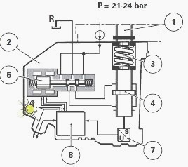
(1) Main electric hydraulic valve spool (2) Electrohydraulic unit (3)
Return spring (4) Piston (5) Pilot valve (6) Digital electronic system
(7) Displacement sensor, FP
- Set of filters (25 microns), P - Pressure, R - Return
Operation of the auxiliary electric hydraulic spool valve
When the spool is moved electric hydraulically upwards by the pilot
valve, oil penetrates via channel P and travels to the flow regulation
control spool restrictor and
the grooves of the main spool.
The oil is then carried towards a main channel and lifts the ball of valve to enter a chamber. Displacement of the spool simultaneously opens the one-way valve.
The oil flows from the chamber towards port B and returns to the
housing through
port A via the hydraulic slave device. The operating principle is
identical when the spool is electro hydraulically moved down by the
pilot valve.
The oil then flows from the chamber towards port A and returns to the
housing through port B via the hydraulic slave device. The
electrohydraulic spool valves can
be manually controlled using a lever screwed onto the reversing lever.
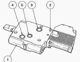
Layout of components and identification of ports
(1) Main spool (2) Valve (3) Non-return valve (4) Pressure balancing
valve (5) Cover
Spool valve assembly
On Massey Ferguson 6615, 6614 tractors where one or more elements of the
auxiliary spool valves are operated mechanically, take care to
disconnect the link
cable(s) without turning the main spool of the valve a half turn.
Place the lift arms in the low position.
Disconnect:
- on mechanically operated spool valves - control cable, taking the
above reminder into consideration;
- on Joystick or lever operated (Dual Control) spool valves - solenoid
valve, connector(s) linked to the spool valve electrohydraulic unit(s),
marking their position(s).
Removing the spool valves
The spool valve block assembly must be removed complete before working
on it. Any operations carried out on the spool valves require scrupulous
cleanliness.
First correctly clean the spool valves (lift control and auxiliary) and
the areas around them before removing them.
If necessary, remove all the spool valves one after the other and
disconnect the hydraulic connections as they are removed.
Removing the lift control spool valve
Take off the supply and return pipes.
Disconnect the connectors of the lifting and lowering solenoid valves.
The brown connector is connected to the right-hand solenoid valve used to lower the lift control.
Remove the spool valve assembly.
Remove lift control spool valve.
Removing the inlet block
In order to fit the MF 6615, 6614 auxiliary spool valves in horizontal
position, it is necessary to remove the spool valve block assembly.
Loosen the P – R and LS unions, disconnect the hydraulic union and
electrical connectors, and remove the spool valve block. Remove the
inlet block.
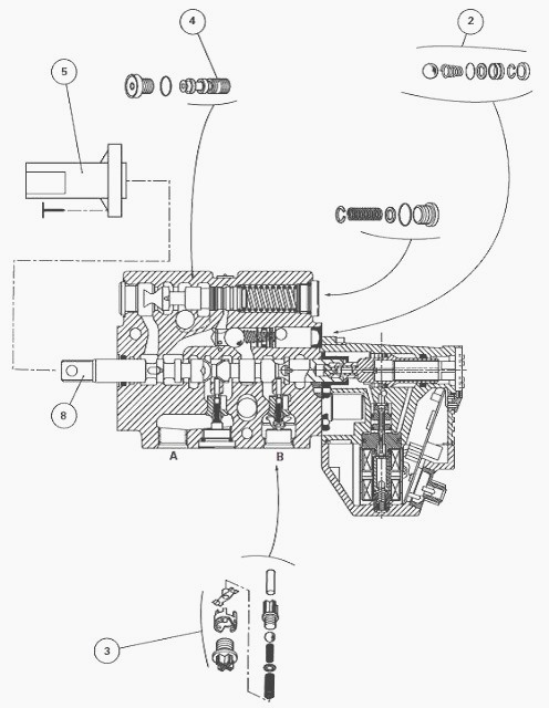
Install the spool valves
Wipe clean the mating faces of the inlet block, the lift control spool
valve, the auxiliary spool valves and the end plate.
Check that each
element is perfectly flat.
Check the tightness of the studs on the inlet block.
Position the new seals (2) (3) (4) and (5) on each element of the
distribution block (1).
Assemble the distribution block on the workbench by superposing the
elements and following the assembly procedure.
Reinstall fit the complete block on the Massey Ferguson 6614, 6615
tractor.
Reconnect the hydraulic pipes and electrical connectors.
Reconnect:
On mechanically operated spool valves
- the lifting and lowering solenoid valve connectors in accordance with
marks made during removal,
- the control cable(s);
On Joystick or lever operated (Dual Control) spool valves
- the lifting and lowering solenoid valve connectors in accordance with
marks made during removal,
- the connector(s) linked to the electrohydraulic unit(s), according to
marks made during removal,
- the solenoid valve located on the end plate.
Start the engine, place the lift control arms in the low position.
At each position, check the operation of:
- the hydraulic system.
- electronic system.
Check the oil tightness of the spool valves and hydraulic unions.
Assembly procedure
To obtain the correct assembly of seals (2) to (5), the reassembly of
each spool valve must be carried out vertically on the workbench.
In this order, stack the input unit, an auxiliary spool valve, a support
block, the lift control valve, an additional support block, and the
auxiliary spool valves.
Place a steel ruler R thrust against face F of the distribution block so
as to align the fixing points equally and correctly.
Tighten the nuts to a torque of 30 - 33 Nm. After the assembly of the spool valves, carry out the reassembly operations.
________________________________________________________________________________
________________________________________________________________________________________
 SPECS
SPECS LOADERS
 MAINTENANCE
 PROBLEMS
________________________________________________________________________________________
 MF 1523
 MF 1531
 MF 135
 MF 1547
 MF 1635
________________________________________________________________________________________
________________________________________________________________________________________
 231
231 231S
231S 235
235 240
240 241
241________________________________________________________________________________________
 255
255 265
265 274
274 285
285 375
375________________________________________________________________________________________
________________________________________________________________________________________
 916X Loader
 921X Loader
 926X Loader
 931X Loader
 936X Loader
________________________________________________________________________________________
 941X Loader
 946X Loader
 951X Loader
 956X Loader
 988 Loader
________________________________________________________________________________________
 1655
1655 GS1705
 1742
1742 2635
2635 4608
4608________________________________________________________________________________________
 1080
1080 1100
1100 2615
2615 3050
3050 3060
3060________________________________________________________________________________________
 4708
4708 5455
5455 5450
5450 5610
5610 5613
5613________________________________________________________________________________________
 DL95 Loader
 DL100 Loader
 DL120 Loader
 DL125 Loader
 DL130 Loader
________________________________________________________________________________________
 DL135 Loader
 DL250 Loader
 DL260 Loader
 L90 Loader
 L100 Loader
________________________________________________________________________________________
 6499
6499 7480
7480 7618
7618 7726
7726 1533
1533________________________________________________________________________________________
 2604H
2604H 2607H
2607H 4455
4455 4610M
4610M 4710
4710________________________________________________________________________________________
 L105E Loader
 L210 Loader
 1014 Loader
 1016 Loader
 1462 Loader
________________________________________________________________________________________
 1525 Loader
 1530 Loader
 232 Loader
 838 Loader
 848 Loader
________________________________________________________________________________________
 5712SL
 6713
6713 6715S
6715S 7475
7475 7615
7615________________________________________________________________________________________
 7716
7716 7724
7724 8240
8240 8650
8650 8732
8732________________________________________________________________________________________
 246 Loader
 1036 Loader
 1038 Loader
 1080 Loader
 856 Loader