
________________________________________________________________________________
Massey Ferguson 7622, 7624 Dyna 6 Transmission - Powershift module
Massey Ferguson 7622, 7624 Dyna 6 transmission (GBA15 gearbox)
Powershift module is housed inside a housing located between the engine
and the gearbox. It provides six ratios at the gearbox input for
shifting under load.
Operating principle of the Powershift module
and its control
MF 7622, 7624 Powershift module comprises:
- the multiplier module
- the Dynashift module.
The multiplier module
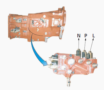
The multiplier module is controlled by proportional solenoids valves N
and P.
It comprises:
- a standard epicyclic gear train;
- a clutch;
- a brake.
Direct drive (ratio 1/1)
The sun gear is attached to the planet carrier via the clutch. Drive
enters via the planet carrier and exits via the ring gear.
Overdrive MF 7624, 7626 transmission (ratio 1.423/1)
The sun gear is immobilised on the gearbox housing by the brake. It
allows the engine speed to go into overdrive when ratios E and F are
engaged.
The Dynashift module
The Dynashift module provides four ratios for shifting under load - A,
B, C and D - controlled by proportional solenoid valves L and N.
It
comprises:
- two standard epicyclic gear trains (primary and secondary);
- two brakes;
- two clutches.
Drive enters and exits via the primary epicyclic gear train. The
clutches/brakes operate on the secondary epicyclic gear train ring gear
and sun gear at an opportune
moment in order to modify the rotational speed of the primary sun gear,
thus creating ratios A, B, C and D of the Dynashift module.
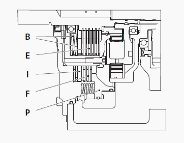
The clutches/brakes that select the multiplier module ratios and the
Dynashift module ratios are each controlled by a piston P. When a brake
is engaged, the related
clutch is disengaged, and vice versa.
Control pistons P operate act both on brake discs F and on junction
plate I. When piston P is under pressure, plate I pushes back Belleville
washers B of clutch E.
When the pressure is released, Belleville washers B push piston P back
via junction plate I and tightens clutch discs E.
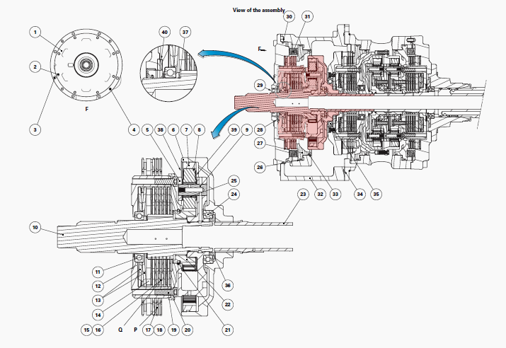
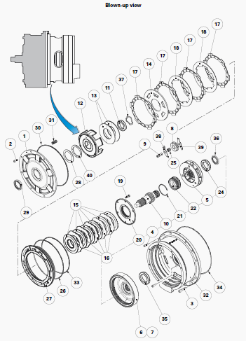
Multiplier module
(1) Cover plate, (2) Screw, (3) Screw, (4) Screw, (5) Planet carrier,
(6) Ring gear carrier, (7) Ring gear, (8) Planet gear, (9) Planet gear
pin, (10) Input shaft, (11) Ball
bearing, (12) Clutch Q bell housing, (13) Belleville washers, (14)
Clutch Q/brake P junction plate, (15) Clutch Q discs, (16) Clutch Q
intermediate plates, (17) Brake
P discs, (18) Brake P intermediate plates, (19) Screw, (20) Clutch Q
cover plate, (21) Snap ring, (22) Sun gear, (23) Dynashift module input
shaft, (24) Ball bearing,
(25) Planet gear needle rollers, (26) "O" ring, (27) Brake P piston,
(28)Washer, (29) Lip seal, (30) "O" ring, (31) Spring, (32) Multiplier
module housing, (33) "O" ring
(34) "O" ring, (35) Ball bearing, (36) Splined washer (bronze), (37)
Waved washer (spring), (38) Wear plate, (39) Wear plate, (40) Friction
washer
Massey Ferguson 7624, 7622 Powershift module control
The Powershift module ratio can be changed via:
- the multifunctional Power Control lever located on the left underneath
the steering wheel;
- the other lever fitted to the right-hand armrest.
In basic operating mode, ratios are shifted in Speedmatching mode. The
most suitable ratio under load is then selected automatically when
shifting range.
Depending on the option, ratio shifting can be completely automatic.
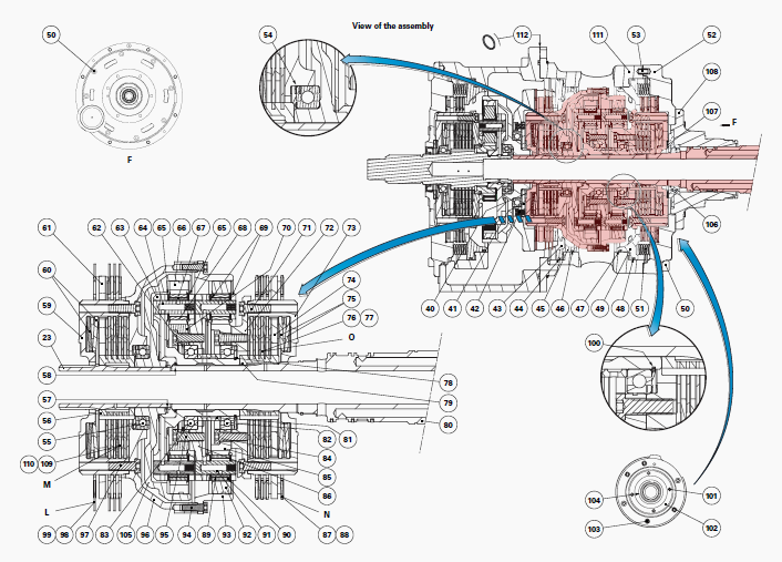
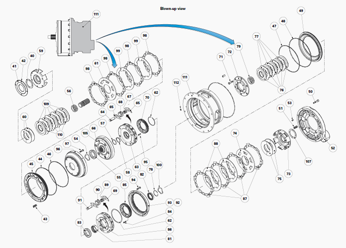
Dynashift module
(40) Friction washer, (41) Thrust washer, (42) Screw, (43) Location of
springs, (44) "O" ring, (45) Brake L piston, (46) "O" ring, (47) "O"
ring, (48) "O" ring, (49)
Brake N piston, (50) Screw, (51) Spring, (52) Rear cover plate of
Dynashift, (53) Dowel, (54) Waved washer (spring), (55) Ball bearing,
(56) Clutch M hub, (57)
Circlip, (58) Snap ring, (59) Clutch M bell housing, (60) Belleville
washers, (61) Clutch M/brake L junction plate, (62) Snap ring, (63)
Primary planet carrier, (64)
Planet gear pin, (65) Wear plates, (66) Primary ring gear, (67) Primary
planet gear needle rollers, (68) Primary planet gear, (69) Wear plates,
(70) Primary sun gear,
(71) Screw, (72) Clutch O cover plate, (73) Clutch O bell housing, (74)
Clutch O/brake N junction plate, (75) Belleville washers, (76) Clutch O
discs, (77) Clutch O,
intermediate plates, (78) Snap ring, (79) Clutch O hub, (80) Shaft/bell
housings, (81) Spacer, (82) Ball bearing, (83) Ball bearing, (84) Screw,
(85) Secondary sun
gear, (86) Secondary planet carrier, (87) Brake N discs, (88) Brake N
intermediate plates, (89) Secondary planet gear needle rollers, (90)
Secondary planet gear,
(91) Planet gear pin, (92) Secondary ring gear, (93) Secondary ring gear
carrier, (94) Screw, (95) Screw, (96) Secondary ring gear/bell housing,
(97) Screw, (98)
Brake L disc, (99) Brake L intermediate plates, (100) Waved washer
(spring), (101) Screw, (102) Thrust plate, (103) Screw, (104) Snap ring,
(105) Primary bell
housing, (106) Bearing with sealed face, (107) Friction washer, (108)
Bush, (109) Clutch M discs, (110) Clutch M intermediate plates, (111)
Dynashift module
housing, (112) "O" ring
Removing and refitting the Powershift module
Disconnect the MF 7622, 7624 tractor between housing (C) of the robotic
gearbox and housing of the Powershift module (C1).
Separate housing C1 from the engine.
Remove the hydraulic control unit located to the right of housing C1
together with its connecting pipes.
From housing C1 remove: the PTO shaft; the reverse layshaft; the reverse
driven gear.
Stabilise housing C1 of the Powershift module in a vertical position on
wooden blocks.
Removal
Unscrew three screws (2) from the multiplier cover plate. In their
place, fit locally obtained flanges B using screws V with the correct
thread length.
Unscrew the eight M10 screws V2 without working on the M8 screws V1.
Unscrewing the M8 screws would cause the Powershift module to separate,
which is not desired.Sling the Powershift module.
To remove the Powershift module from housing C1, proceed as follows:
- Using a suitable sling and hoist, lift the Powershift module slightly
out of housing C1.
- Turn the Powershift module so that lug O of the reverse layshaft gear
is positioned between the two bosses B.
- Tilt the Powershift module steeply towards lug O and continue to lift
it so that it enters groove A (approx. D 310 mm) of housing C1.
- Definitively remove the Powershift module from housing C1.
Remove and discard seal J. Place the Powershift module in a vertical
position on a suitable support S.
Refitting
Lightly smear "O" ring J with miscible grease. Fit it into the groove of
the Powershift module housing (111).
Check that dowel P is present on housing C1. Clean mating face F of the
Powershift module and that of housing C1.
If mating face F of housing C1 was chipped or deformed during the
removal of the Powershift module, smooth it off with fine sandpaper.
To refit the Powershift module in housing C1, proceed as follows:
- Use flanges B and the sling used during removal.
- Mark the location of dowel P with a line of paint on housing C1 and on
the Powershift module.
- Position the Massey Ferguson 7622, 7624 Powershift module at the
opening of groove A of housing C1, positioning lug O of the reverse
layshaft gear between the
two bosses B.
- Tilt the Powershift module steeply towards lug O and continue to lower
it so that it enters groove A of housing C1.
- When it has entered the groove of housing C1, continue to lower the
Powershift module slowly, turning it gently to bring it into position
with the paint lines made
previously. Definitively refit the Powershift module in housing C1.
Screw the eight M10 screws V2. Tighten to 57-77 Nm. On the multiplier
cover plate: Unscrew screws V.
Remove the locally obtained flanges B. Screw in the original screws (2).
Tighten to a torque of 37 Nm.
Stabilise front housing C1 of the Powershift module in a horizontal
position. Refit: the reverse driven gear; the reverse layshaft; the PTO
shaft.
Clean the mating faces: of the hydraulic cover plate; of the hydraulic
control cover plate on housing C1. Check that transfer pipes T are
present.
Lightly smear the mating face of the hydraulic cover plate on housing C1
with Loctite 510 or equivalent.
Do not block low-pressure hydraulic port O (approx. 21 bar) supplying
ranges 1 to 4 of the robotic gearbox.
Refit the hydraulic control unit. Screw in the screw. Tighten to 57-77 Nm. Fit housing C1 to the engine. Reconnect the tractor between housing C of the robotic gearbox and housing C1 of the Powershift module.
________________________________________________________________________________
________________________________________________________________________________________
 SPECS
SPECS LOADERS
 MAINTENANCE
 PROBLEMS
________________________________________________________________________________________
 MF 1523
 MF 1531
 MF 135
 MF 1547
 MF 1635
________________________________________________________________________________________
________________________________________________________________________________________
 231
231 231S
231S 235
235 240
240 241
241________________________________________________________________________________________
 255
255 265
265 274
274 285
285 375
375________________________________________________________________________________________
________________________________________________________________________________________
 916X Loader
 921X Loader
 926X Loader
 931X Loader
 936X Loader
________________________________________________________________________________________
 941X Loader
 946X Loader
 951X Loader
 956X Loader
 988 Loader
________________________________________________________________________________________
 1655
1655 GS1705
 1742
1742 2635
2635 4608
4608________________________________________________________________________________________
 1080
1080 1100
1100 2615
2615 3050
3050 3060
3060________________________________________________________________________________________
 4708
4708 5455
5455 5450
5450 5610
5610 5613
5613________________________________________________________________________________________
 DL95 Loader
 DL100 Loader
 DL120 Loader
 DL125 Loader
 DL130 Loader
________________________________________________________________________________________
 DL135 Loader
 DL250 Loader
 DL260 Loader
 L90 Loader
 L100 Loader
________________________________________________________________________________________
 6499
6499 7480
7480 7618
7618 7726
7726 1533
1533________________________________________________________________________________________
 2604H
2604H 2607H
2607H 4455
4455 4610M
4610M 4710
4710________________________________________________________________________________________
 L105E Loader
 L210 Loader
 1014 Loader
 1016 Loader
 1462 Loader
________________________________________________________________________________________
 1525 Loader
 1530 Loader
 232 Loader
 838 Loader
 848 Loader
________________________________________________________________________________________
 5712SL
 6713
6713 6715S
6715S 7475
7475 7615
7615________________________________________________________________________________________
 7716
7716 7724
7724 8240
8240 8650
8650 8732
8732________________________________________________________________________________________
 246 Loader
 1036 Loader
 1038 Loader
 1080 Loader
 856 Loader