
________________________________________________________________________________
Massey Ferguson 7614, 7615 robotic mechanical gearbox
The GBA25 gearbox is equipped to Massey Ferguson 7614, 7615 tractors
with Dyna 4 transmission. This transmission is fully automated. It
allows shifting between all the ratios without declutching.
The gearbox is divided into two parts:
- The Powershift module, with four ratios for shifting under load.
- The robotically-controlled mechanical gearbox with four ranges.
MF 7614, 7615 transmission assembly is controlled electronically by an
Autotronic 5 calculator. The GBA25 Dyna-4 gearbox has 16 ratios.
These
are provided by 4
Powershift module ratios for shifting under load, and 4 mechanical
gearbox ranges. The mechanical gearbox ranges are controlled like a
ratio for shifting under load.
The ratios are controlled by two levers:
- Power control lever located under the steering wheel.
- gear shift lever located on the armrest.
The mechanical gearbox is located between the Powershift module and the
rear axle. It comprises two shafts (upper and lower shaft lines), on
which four gear trains
with helical teeth rotate.
Input drive is supplied by the Power Shuttle
and is transmitted to the upper shaft line. Output drive is transmitted
via the lower shaft line to a
creeper unit or directly to the crown wheel and pinion.
The lubricating oil coming from the 5 bar valve of the MF 7615, 7614
tractor is sent to the gearbox lower shaft line and upper shaft line. A
network of internal
channels directs the oil to the elements requiring lubrication.
Selecting ratios
Ratios are selected using two synchronisers, one single cone and one
double cone. Each synchroniser is engaged individually.
The synchronisers are controlled by two selector rails and two forks. Each selector rail has a double-acting piston, allowing range shifting.
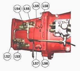
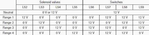
The selector rail pistons are controlled hydraulically via the Massey Ferguson 7614, 7615 tractor 20 bar circuit. Four solenoid valves (L52, L53, L54, L55) located on the right-hand side of the gearbox control selector rail movement.
Four switches (L56, L57, L58, L59) inform the calculator of
the selector rail positions. The switches are pressed in by pins (130).
Each range has a
corresponding solenoid valve and switch.
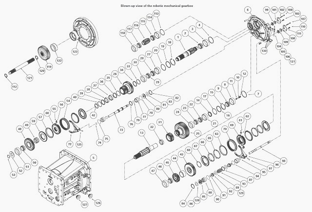
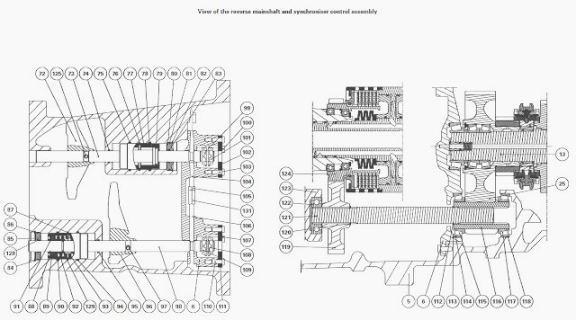
(1) Primary shaft (2) Bearing cone (3) Bearing cup (4) Shims (5) Gearbox
housing (6) Cover (7) Shims (8) Bearing cup (9) Bearing cone (10) "O"
ring (11) Spring
(12) Lubrication pipe (13) Secondary shaft
(14) Spacer (15) Circlip (16) Washer (17) Shims (18) Circlip (19) Washer
(20) Shims (21) Bearing cup (22) Bearing cone (23) Bearing cone (24)
Bearing cup (25)
Pinion (26) Double pinion (27) Bearing cup (28) Bearing cone (29)
Bearing cone (30) Bearing cup (31) Pinion (32) Needle bearing (33)
Washer
(34) Circlip (35) Circlip (36) Spacer (37) Needle bearing (38) Needle
bearing (39) Spacer (40) Circlip (41) Shims (42) Circlip (43) Pinion
(44) Spacer (45) Pinion (46)
Bearing cone (47) Bearing cup (48) Pinion
(49) Ring (50) Bearing cone (51) Bearing cup (52) Deflector (53) Ring
(54) Sliding coupler (55) Ball bearing (56) Pressure connector (57)
Brake (58) Spring (59)
Flange (60) Hub (61) Ball bearing (62) Pressure connector (63) Ring (64)
Spring (65) Brake (66) Cone (67) Flange (68) Snap ring (69) Hub
(70) Sliding coupler (71) Power take-off shaft (72) Fork (73) Selector
rail (74) "O" ring (75) "O" ring (76) Circlip (77) Sleeve (78) "O" ring
(79) "O" ring (80) Plug (81)
"O" ring (82) Circlip (83) "O" ring (84) Circlip (85) Plug (86) "O" ring
(87) Circlip (88) Sleeve (89) "O" ring (90) "O" ring (91) Snap ring
(92) Piston (93) Spring (94) "O" ring (95) "O" ring (96) Fork (97) Pin
(98) Selector rail (99) Castellated nut (100) Screws (101) Castellated
nut (102) Plate (103)
Screws (104) Rail (105) Locknut (106) Rail
(107) Screws (108) Castellated nut (109) Castellated nut (110) Screws
(111) Plate (112) Circlip (113) Shims (114) Bearing cup (115) Bearing
cone (116) Pinion
(117) Bearing cone (118) Bearing cup (119) Pinion (120) Circlip (121)
Shaft (122) Bearing (123) Powershift module cover (124) Reverse pinion
hub (125) Pin (126)
Plug (127) Plug (128) "O" ring (129) "O" ring (130) Pin (131) Reverse
pitch nut
Description and kinematics of ratios
The MF 7614, 7615 robotic gearbox allows four ratios to be obtained with
only four gear trains, two shafts and two synchronisers.
Kinematics
Range 1 - The reduction is carried out on three gear trains. The first gear train
drives the second train via the 1st gear synchronisers, then the third
train.
Range 2 -
The reduction is carried out on the first gear train. The 2nd gear
synchronisers secure the 2nd gear pinion to the secondary shaft.
Range 3 -
The reduction is carried out on the third gear train. The primary shaft
is secured to the 3rd gear pinion by the 3rd gear synchronisers.
Range 4 - The reduction is carried out on the fourth gear train. The primary shaft
is secured to the 4th gear pinion by the 4th gear synchronisers.
In forward position, input drive comes directly from the Power Shuttle
to the primary shaft (1). In reverse position, drive comes from the
Power Shuttle via the
pinions (124), (119) and (116) and the shaft (121). It enters via the
second driven pinion (25), which is constantly meshed to the primary
shaft (1).
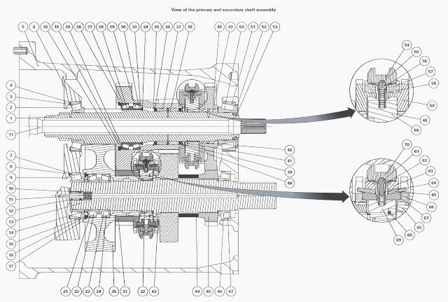
Primary shaft
The primary shaft (1) is splined to the Power Shuttle forward hub. It is
supported by two taper roller bearings (3)(4) and (50)(51) Adjustment is
controlled by shims
(4).
The PTO shaft (71) is inserted through the centre of the primary
shaft (1). This cavity in the shaft (1) also serves as a channel for
lubricating oil.
The first and second driving gear is cut into the primary shaft (1). The double pinion (26) turns idle on the shaft (1) and is supported by two taper roller bearings (27) (28) and (29)(30) and two needle bearings (37)(38).
This pinion is
supported on the shaft by shims (20). The fourth driving gear turns idle
on the shaft (1). It is
supported by a lubricated bush (49).
Secondary shaft
The secondary shaft (13) turns on two taper roller bearings (8)(9) and
(46)(47). Bores in the centre of the shaft (13) ensure proper
lubrication.
Adjustment is
controlled by shims (7). The pinion (25) turns truly on the shaft (13)
and is supported by two taper roller bearings (21)(22) and (23)(24) and
a needle bearing (32).
The pinion (25) acts as a bearing to the idle pinion (31). This pinion
(31) is in direct contact with the pinion (25). A layer of oil ensures
the mating faces are lubricated.
The pinions (43) and (45) are splined to the shaft (13). They are
separated by a spacer (44).
Synchronisers
The single cone synchroniser located on the primary shaft (1) allows
shifting between the third and fourth gears. Its hub (60) is splined to
the shaft (1). It is held in
position by a circlip (42) on one side and by the bearing cone (50)
fitted tightly on the shaft (1).
By moving the slider (54), the shaft (1) is locked either:
- with the double pinion (26) (3rd)
- with the pinion (48) (4th).
The double cone synchroniser located on the secondary shaft (13) allows
shifting between the first and second gears. Its hub (69) is integral
with the pinion (25). It is
held in position by the snap ring (68).
By moving the slider (70), the shaft (13) is locked either:
- with the idle pinion (31) (1st)
- or with the pinion (43) (2nd).
Selecting ratios
The synchronisers are controlled conventionally by forks (72) and (96)
and selector rails (73) and (98). The selector rails are controlled
hydraulically. The selector
rails are controlled by double-acting pistons.
On the selector rail (98) that controls the 1st and 2nd gear
synchroniser, the piston (92) is damped by a spring (93) to give smooth
shifting between ranges 1 and 2.
The selector rails are adjusted by tightening or loosening the castellated nuts (99)(101) and (108)(109). Once adjusted, the stops are held in position by screws (100) and (107).
An interlock mechanism comprising two rods (104)(106) and a locknut (105) prevents the selector rails from being engaged simultaneously. When one selector rail is engaged, the pin locks the other rail in a groove.
________________________________________________________________________________
________________________________________________________________________________________
 SPECS
SPECS LOADERS
 MAINTENANCE
 PROBLEMS
________________________________________________________________________________________
 MF 1523
 MF 1531
 MF 135
 MF 1547
 MF 1635
________________________________________________________________________________________
________________________________________________________________________________________
 231
231 231S
231S 235
235 240
240 241
241________________________________________________________________________________________
 255
255 265
265 274
274 285
285 375
375________________________________________________________________________________________
________________________________________________________________________________________
 916X Loader
 921X Loader
 926X Loader
 931X Loader
 936X Loader
________________________________________________________________________________________
 941X Loader
 946X Loader
 951X Loader
 956X Loader
 988 Loader
________________________________________________________________________________________
 1655
1655 GS1705
 1742
1742 2635
2635 4608
4608________________________________________________________________________________________
 1080
1080 1100
1100 2615
2615 3050
3050 3060
3060________________________________________________________________________________________
 4708
4708 5455
5455 5450
5450 5610
5610 5613
5613________________________________________________________________________________________
 DL95 Loader
 DL100 Loader
 DL120 Loader
 DL125 Loader
 DL130 Loader
________________________________________________________________________________________
 DL135 Loader
 DL250 Loader
 DL260 Loader
 L90 Loader
 L100 Loader
________________________________________________________________________________________
 6499
6499 7480
7480 7618
7618 7726
7726 1533
1533________________________________________________________________________________________
 2604H
2604H 2607H
2607H 4455
4455 4610M
4610M 4710
4710________________________________________________________________________________________
 L105E Loader
 L210 Loader
 1014 Loader
 1016 Loader
 1462 Loader
________________________________________________________________________________________
 1525 Loader
 1530 Loader
 232 Loader
 838 Loader
 848 Loader
________________________________________________________________________________________
 5712SL
 6713
6713 6715S
6715S 7475
7475 7615
7615________________________________________________________________________________________
 7716
7716 7724
7724 8240
8240 8650
8650 8732
8732________________________________________________________________________________________
 246 Loader
 1036 Loader
 1038 Loader
 1080 Loader
 856 Loader