
________________________________________________________________________________
Massey Ferguson 7720, 7726, 7480, 7495 Dyna VT transmission PTO
Disassembling the Dyna VT transmission power
take-off
Lower the rear linkage. Drain the transmission oil. Remove the trailer
linkage (depending on equipment). Mark and remove the PTO connector TR9.
Mark and remove the PTO connector TR10. Unscrew all attachment screws.
Take the silicone out of the threaded bores and tighten 2 screws M12
Support the cover using a lifting tool and push it back using the two
screws.
Take off the Massey Ferguson 7480, 7495 rear PTO transmission cover.
Take care of the adjustment shims, which are used to adjust the bearing
clearance.
Push back the clutch cover (3) using 2 disc screws M10.
Remove the nozzle (29). Fit the compression tool and
compress the clutch. Extract the locking half-rings (30).
Release the clutch. Remove the disc carrier and the set of discs (10).
Remove the adjustment shims (8), the set of Belleville washers (9) and
the ring (14). Remove the piston (13). Remove a screws (21) and take off
the blade (18).
Take off the circlip (31) and remove the brake disc
(20). Take off the brake disc. Extract the bearing (101) using an
extractor. Take out the washer. Unscrew the nuts (210 and 211). Note the
values of the nuts (210 and 211) if required. Remove the stops (116).
Take out the control mechanism. Remove the pinions (118) and (118a).
Take out the shaft (35). If required, take off the external rings of the
bearing. If necessary, remove the ram (217) and or (226). Take off the
circlip (107), washer (108) and pinions. Remove the circlip (112).
Release the pinion (118).

Massey Ferguson 7720, 7726 Power take-off clutch
1 - Shim, 2 - Taper roller bearings, 3 - Clutch cover, 4 - Cylindrical
screw, 5 - Shim, 6 - Internal blade holder, 8 - Shim, 9 - Spring washer,
10 - Set of blades, 11 - Disc, 12 - Intermediate plate, 13 - Piston, 14
- Ring, 16 - Lip seal, 18 - Plate, 19 - Lip seal, 20 - Brake disc, 21 -
Allen screw, 22 - Grower washer, 23 - Bush, 25 - Pinion, 28 - Taper
roller bearing, 29 - Nozzle, 30 - Locking half-rings, 31 - Circlip, 32 -
O’ring, 35 - Shaft, 36 - Taper roller bearing, 37 - Ring with
rectangular section, 38 - Grub screw, 39 - Nozzle, 40 - Sensor, 42 -
Shaft
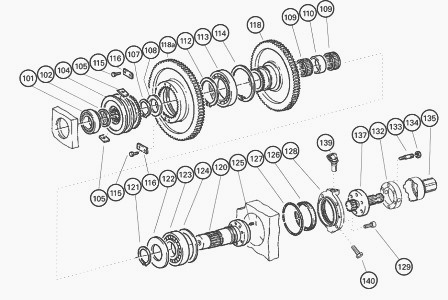
MF 7720, 7726, 7480, 7495 Rear PTO drive
101 - Taper roller bearing, 102 - Shim, 104 - Clutch body, 105 - Roller,
107 - Circlip, 108 - Washer, 109 - Needle bearing cage, 110 - Spacer,
112 - Circlip, 113 - Taper roller bearing, 114 - Circlip, 115 - Allen
screw, 116 - Stop, 118 - Pinion (1000 rpm), 118A - Pinion (540 or 750
rpm), 120 - Shaft, 121 - Circlip, 122 - Washer, 123 - Taper roller
bearing, 124 - Shim, 125 - Grub screw, 126 - Spi seal, 127 - O’ring, 128
- Bearing cover, 129 - Cylindrical screw, 132 - Spacer, 133 - Threaded
stud M10 x 50 - 10.9, 134 - Nut M10-10, 135 - PTO guard, 137 -
End-fitting, 139 - Sensor, 140 - Allen screw
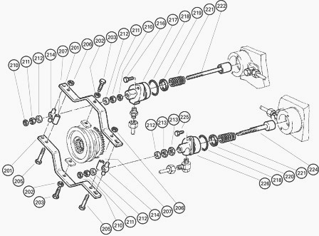
MF 7720, 7726 Rear PTO control
201 - Stirrup, 202 - Hexagonal nut, 203 - Stud, 205 - Allen screw, 206 -
Hexagonal nut, 207 - Spacer pipe, 210 - Hexagonal nut, 211 - Hexagonal
nut, 212 - Washer, 213 - Hexagonal nut, 214 - Roller, 216 - Allen screw,
217 - Rams, 218 - O’ring, 219 - Compact seal, 220 - Compact seal, 221 -
Spring, 222 - Piston, 224 - Piston, 225 - Allen screw, 226 - Rams
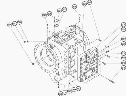
Rear Power take-off cover
301 - Rear axle housing, 303 - Seal, 304 - Cover, 305 - Allen screw, 307
- Closing plug, 308 - Sealing ring, 309 - Closing plug, 310 - Sealing
ring, 311 - Closing plug, 315 - Dowel pin, 316 - Housing cover, 317 -
Screw M18 x 90 - 10.9, 318 - Screw M18 x 110 -10.9, 319 - Threaded stud
M18 x 130 - 10.9, 322 - Sealing ring, 325 - Cylindrical screw
Disassembling Massey Ferguson 7720, 7726 Dyna VT transmission power
take-off
Fit home the bearing (113) in the pinion (118a) and lock with the
circlip (114), then fit the pinion (118) to its stop. Fit the circlip
(112) on the opposite side.
Fit home the internal ring of the bearing (123) on the shaft (120). Position the washer (122). Fit the circlip (121). Smear the 2 grub screws (25) with plastic binder and tighten them until the internal ring of the bearing (123) reaches its stop.
The washer (122) must be fitted
home. Fit the 1st needle bearing cage (109), the spacer (110) and the
2nd needle bearing cage (109) on the shaft (120). Fit the shaft (120).
Position the washer (108). Fit the circlip (107). Fit new seals (219) in
the ram (217).
Fit a new O’ring (218) in the groove of the ram (217). Smear the oil tight seals with miscible grease. Insert the piston (222) and spring (221) as indicated in the ram (217).
The oil tight seal (219) is
comprised of 2 parts: an O’ring on the outside and a piston strip guide
on the inside.
Fit new seals (220) in the ram (226). Fit a new O’ring (218) in the
groove of the ram (226). Smear the oil tight seals with miscible grease.
Insert the piston (224) and spring (221) as indicated in the ram (226).
The oil tight seal (219) is comprised of 2 parts: an O’ring on the
outside and a piston strip guide on the inside. Fit the rams (217 and
226). Smear the thread of the screws (216 and 225) with plastic binder
and tighten the
screws to the following torque: 49 Nm
Refit the hydraulic pipes which have been removed in the housing cover
(316).
If the housing is fitted with a new cover (316), screw the nozzle (29)
to its stop in the threaded bore. Fit home the external ring of the
bearing (36).
Smear 2 new rings (37) with miscible grease and install and lock them in
the grooves of the shaft (35). Fit home the internal ring of the bearing
(36).
When assembling a new shaft (35), smear the thread of the threaded stud (38) with plastic binder, and screw to its stop. Tighten the nozzle (29) to its stop. Fit the pre-assembled shaft (35) in the housing cover (316).
If required, fit compensating shims (124) and fit home the
external ring of the bearing (123). Fit the pair of ring gears and the
pinion (25).
Pre-assembling the stirrup
Smear the thread of the screws (205) with plastic binder.
Fit spacers (207) and rollers (214). Tighten nuts (206). Insert the
rollers (105) into the clutch body (104). Smear the thread of the screws
(203) with plastic binder. Fit the stirrup tight to an identical
distance, then loosen each screw (203) by 1/6 of a turn and lock them in
this position.
Screw the nuts (ref. 210, 211 and 213) onto the rods of the pistons (222, 224). Fit the washers (212) with their chamfer turned upwards. Fit the pre-assembled stirrup (201). Fit the washers (212) with their chamfer turned downwards. Unscrew the nuts (210 and 211). Smear the thread of the screws (115) with plastic binder.
Fit the stops (116) and
lock the screws (115). The following must be carried out before setting
stirrup travel:
The oblong hole in the stirrup (201) must be turned towards the ram
(226).
Screw and lock the nuts (211, 210) to their stop. Screw a locally made
eye nut M12 onto the piston rod of the ram (217).
Using a lifting tool, pull hard on the piston rod. (Coupling at 750 or 540 rpm). Check the clearance of the clutch body (104). Specified value: 0.1 to 0.2 mm clearance. If outside the specified clearance: Adjust with nuts M12 (top and bottom) until clearance of 0.1 to 0.2 mm is obtained.
Take off the lifting tool and unscrew the eye nut M12.
Push the piston rod of the ram (226) fully in using a clamp, until the
nuts (213) and at their stop. (Lifting limit, 1000 rpm position).
Check the clearance of the clutch body (104). Specified value: 0.1 to
0.2 mm clearance. If outside the specified clearance:
Adjust the nuts (213) until clearance of 0.1 to 0.2 mm is obtained.
Take off the clamp. The coupling shifts to "Neutral" position. The 750 or 540 and 1000 rpm ring gears should be able to turn freely. The upward and downward free travel of the coupling should be identical. If not, readjust the coupling. Fit the shim (102). Fit the internal ring of the bearing (101) up against the shaft (120).
Fit the pinion (25). Smear a new O’ring with miscible grease and fit it in the groove of the shaft (35). Check the brake disc (20) for wear. If necessary, fit a new brake disc (20). Fit the circlip (31). Smear a new lip seal (19) with miscible grease and fit it in the brake disc groove, with the seal lips turned towards the oil chamber.
Fit the blade (18). Smear the thread of the screw (21) with Loctite, and fit the Grower washer (22) and socket (23). Tighten the screw. Smear a new lip seal (16) with miscible grease and fit it in the inner groove of the piston, with the seal lips turned towards the oil chamber. Fit the pre-assembled piston (13). Fit the ring (14).
Fit 5 Belleville
washers (9) with the large external diameters facing each other, and the
compensating shims (8). The external diameter of the first Belleville
washer (9) should be turned towards the ring (14) of the piston (13). If
required, for example if compensating shims (8) are lost, set the
preload of the Belleville washer set (9).
Setting the preload of Belleville washer set
Remove the shim (5) from the internal disc carrier (6).
Smear the thread of the screw (4) with plastic binder and tighten. Fit
home the pre-assembled ring carrier (6).
Measure and note the distance between the disc carrier (6) and the end
of the shaft (35). Example: 23.2 mm.
Fit the compression tool and compress the set of Belleville washers (9).
Fit the locking half-rings (30).
If the locking half-rings (30) are chamfered on just one side, the chamfered side must face the disc carrier (6). Remove the compression tool.
Measure and note the distance between the disc carrier (6) and the end of the shaft (35). Example: 25.8 mm. If the washer set gives compensating clearance of approximately 2.5 mm when completely compressed, the preload is correct. If not, correct it with compensating shims.
________________________________________________________________________________
________________________________________________________________________________________
 SPECS
SPECS LOADERS
 MAINTENANCE
 PROBLEMS
________________________________________________________________________________________
 MF 1523
 MF 1531
 MF 135
 MF 1547
 MF 1635
________________________________________________________________________________________
________________________________________________________________________________________
 231
231 231S
231S 235
235 240
240 241
241________________________________________________________________________________________
 255
255 265
265 274
274 285
285 375
375________________________________________________________________________________________
________________________________________________________________________________________
 916X Loader
 921X Loader
 926X Loader
 931X Loader
 936X Loader
________________________________________________________________________________________
 941X Loader
 946X Loader
 951X Loader
 956X Loader
 988 Loader
________________________________________________________________________________________
 1655
1655 GS1705
 1742
1742 2635
2635 4608
4608________________________________________________________________________________________
 1080
1080 1100
1100 2615
2615 3050
3050 3060
3060________________________________________________________________________________________
 4708
4708 5455
5455 5450
5450 5610
5610 5613
5613________________________________________________________________________________________
 DL95 Loader
 DL100 Loader
 DL120 Loader
 DL125 Loader
 DL130 Loader
________________________________________________________________________________________
 DL135 Loader
 DL250 Loader
 DL260 Loader
 L90 Loader
 L100 Loader
________________________________________________________________________________________
 6499
6499 7480
7480 7618
7618 7726
7726 1533
1533________________________________________________________________________________________
 2604H
2604H 2607H
2607H 4455
4455 4610M
4610M 4710
4710________________________________________________________________________________________
 L105E Loader
 L210 Loader
 1014 Loader
 1016 Loader
 1462 Loader
________________________________________________________________________________________
 1525 Loader
 1530 Loader
 232 Loader
 838 Loader
 848 Loader
________________________________________________________________________________________
 5712SL
 6713
6713 6715S
6715S 7475
7475 7615
7615________________________________________________________________________________________
 7716
7716 7724
7724 8240
8240 8650
8650 8732
8732________________________________________________________________________________________
 246 Loader
 1036 Loader
 1038 Loader
 1080 Loader
 856 Loader