
________________________________________________________________________________
Massey Ferguson 8150, 8210, 8220 gearbox – Layshaft
The layshaft and its pinions form the upper transmission line of the Massey Ferguson 8150, 8210, 8220 heavy gearbox with mechanical reverse shuttle or Power shuttle.
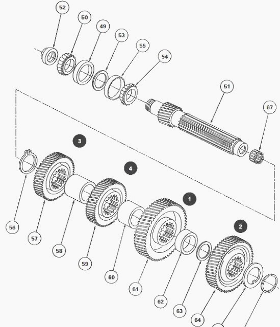
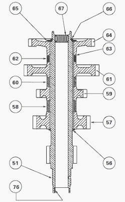
Shaft (51) bears, in this order, the driving pinions of 2nd gear (64), 1st gear (61), 4th gear (59) and 3rd gear (57). These pinions are splined to the shaft and separated by spacers (62) (60) and (58).
Axial clearance of the gear train is provided by one or more shims (63). The rear teeth of the layshaft (51) continuously engage the Tortoise pinion mounted on the output shaft.
The front of the shaft is supported by a roller bearing fitted to the
rear of the input unit. Its rear extremity is
supported by two taper roller bearings (49) (50) and (54) (55).
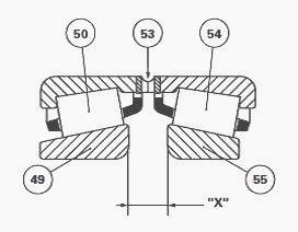
The adjustment of these bearings is of the "Semi Set Right" type. It is carried out by placing a shim (53) between the bearing cones (50) (54) in order to obtain a clearance of a predetermined value between the cups (49) (55).
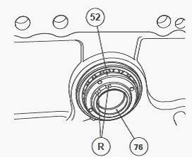
The friction ring (76) forms an oil tight link of the upper shaft line between the MF 8210, 8220 gearbox and the intermediate housing. It is adjusted and sealed with
Loctite 648 or its equivalent in the rear bore of the shaft. Shim (53)
has several radial ports permitting lubrication of bearings (49) (50)
and (54) (55).
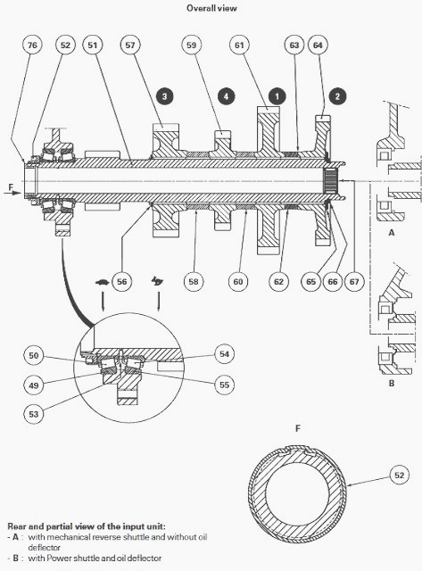
(49) Bearing cup (50) Bearing cone (51) Layshaft (52) Nut (53) Shim (54)
Bearing cone (55) Bearing cup (56) Circlip (57) 3rd gear driven pinion
(58) Spacer (59) 4th gear driven pinion (60) Spacer (61) 1st gear driven
pinion (62) Spacer (63) Shim(s) (64) 2nd gear driven pinion (65) Washer
(66) Snap ring (67) Needle bearing (76) Friction ring with shoulder
To take out the layshaft it is necessary to remove the gearbox.
Uncouple the Massey Ferguson 8150, 8220 tractor between the gearbox and
the intermediate housing.
Separate the gearbox from the engine. Take off the selector cover.
Place the gearbox on a suitable fixture. Remove the input unit.
Disassemble the selector rails and the forks.
Where necessary, immobilise the gear train in the gearbox. Unlock and
slightly loosen nut (52) with the aid of an appropriate chisel in order
to overcome the resistance of the Loctite.
Of course, this nut is replaced during reassembly. This operation
facilitates the removal of the nut with the service tool once the output
shaft and mainshaft have been disassembled. Remove the output shaft.
Remove the mainshaft.
Removing and disassembling the layshaft
Finish unscrewing the nut (52) using service tool and remove bearing
cone (50).
Keep the bearing cups and cones together if they are to be re-used.
Take out the shaft (51) and pinion assembly.
Remove the shim (53) and take off the cone (54).
Where necessary, drive off the cups (49) (55) and mark their locations.On shaft (51) remove the snap ring (66) and washer (65) and mark the locations.
Take off the 2nd gear pinion (64), shim(s) (63), spacer (62),
1st gear pinion (61),
spacer (60), 4th gear pinion (59), spacer (58), 3rd gear pinion (57) and
circlip (56).
If necessary, drive off needle bearing (67).
Reassembling and install the Layshaft
Clean and inspect the components. Replace the defective parts.
On the shaft, check that the lubricating ports leading to the bearing
cones (50) (54) are not blocked. Check for the presence of friction ring
(76).
If disassembled, insert the needle bearing (67) to thrust against the
shoulder of shaft (51) with the aid of a suitable fixture.
Check that the needle bearings turn freely in the cage after insertion.
Install a new circlip (56). Replace the 3rd gear pinion (57), spacer (53), 4th gear pinion (59), spacer (60), 1st gear pinion (61) and spacer (62). Replace 2nd gear pinion (64) without the shims (63).
Carry out the shimming of the
pinions. Shim the pinions. If necessary, shim the bearings (54) (55) and (49) (50).
Lubricate the cones (50) (54) and the bearing cups (49) (55).
If disassembled, insert the cups to thrust against the shoulder of the
housing, with large cup (49) fitted into the rear bore of the Massey
Ferguson 8150, 8210, 8220
gearbox.
Slide cone (54) onto shaft with shim (53) the thickness of which has
been determined at operation 46.
Place the assembled shaft in the housing. Install cone (50).
Pre-tighten
nut (52) in contact with the cone (50).
This nut will be definitively tightened to torque once the input unit
has been refitted, in order to obtain the correct alignment of the
layshaft in the two bearings.
Reassemble the layshaft. Reassemble the output shaft. Install the input unit. Tighten nut (52) to a torque of 50 Nm. Rotate the layshaft several times to progressively seat the bearings.
Carry out final tightening of the
nut to a torque of 100 -
150 Nm, the threads having previously been lightly smeared with Loctite
270 or equivalent.
Lock the nut by bending the collar without breaking it into grooves "R" on the shaft with the aid of an appropriate pin punch. Reassemble and adjust the gear selector device.
Install the selector cover.
Check that the gears change correctly and that the Hare / Tortoise
position functions.Couple the gearbox to the engine.
Couple the MF 8220, 8150 tractor between the gearbox and the
intermediate housing.
Check the oil tightness of seals and hydraulic unions.
Road test the clutch controls, the A, B, C, D ratios of the Dynashift
mechanical reverse shuttle or power shuttle, the gears and the Hare /
Tortoise range.
Shimming the pinions
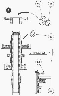
The pinions must be stacked with the shims (63) temporarily removed.
Using a set of feeler gauges, measure the distance between the 2nd gear
pinion (64) and spacer (62).
In relation to the measurement, determine the required thickness of the
shim(s) (63) in order to obtain a clearance of: J1 = 0.02 to 0.31 mm.
If possible, preferably shim towards the nominal tolerance.
Remove snap ring (66) and washer (65). Remove the 2nd gear pinion.
Slide the previously selected definitive shims on to the shaft.
Refit
the pinion and washer (65), turning the chamfer to the exterior. Install
a new snap ring (66) and
check that it is correctly positioned.
Install the assembled shaft with its pinions into the MF 8150, 8210,
8220 gearbox housing. Carry out the remaining operations.
Shimming the bearings
- The principle consists in defining the thickness of the shim (53) to
be fitted between the bearing cones (50) (54) under load (500 N) and in
order to obtain an "X"
measurement of 8.60 to 8.68 mm between cups (49) (55) mounted loose.
- Bearings will be shimmed before refitting the layshaft. If the removed
bearings which, extract cups (49) (55) from the gearbox housing when
pairing them with their
respective cones.
Install bearing cones (50) (54) and cups (49) (55) without shim (53) on
service tool. Tighten the tool in a vertical position in a vice.
Compress the spring until the shoulder of the special bolt is in contact
with the top of the tool.
The spring characteristics and the length of the bolt shoulder provide
the correct load to apply to the
bearings.
Turn cylinder "C" several times, in order to correctly seat the cones in
the cups.
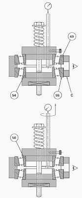
Measure the distance between the bearing cones (50) (54). Position the
pressure plate of the tool on the face of the cone (54). Place the index
of the dial gauge on
the extremity of the pressure plate.
On the dial gauge:
- set the long hand to zero
- note the position of the short hand
Turn the pressure plate half a turn while maintaining it on the face of
the cone (50). Immobilise the rod by moderately manually tightening the
stop bolt.
In relation to the measurement noted on the dial gauge, select the corresponding shim (53) to be definitively fitted between the bearing cones (50) (54). Carry out the remaining operations.
________________________________________________________________________________
________________________________________________________________________________________
 SPECS
SPECS LOADERS
 MAINTENANCE
 PROBLEMS
________________________________________________________________________________________
 MF 1523
 MF 1531
 MF 135
 MF 1547
 MF 1635
________________________________________________________________________________________
________________________________________________________________________________________
 231
231 231S
231S 235
235 240
240 241
241________________________________________________________________________________________
 255
255 265
265 274
274 285
285 375
375________________________________________________________________________________________
________________________________________________________________________________________
 916X Loader
 921X Loader
 926X Loader
 931X Loader
 936X Loader
________________________________________________________________________________________
 941X Loader
 946X Loader
 951X Loader
 956X Loader
 988 Loader
________________________________________________________________________________________
 1655
1655 GS1705
 1742
1742 2635
2635 4608
4608________________________________________________________________________________________
 1080
1080 1100
1100 2615
2615 3050
3050 3060
3060________________________________________________________________________________________
 4708
4708 5455
5455 5450
5450 5610
5610 5613
5613________________________________________________________________________________________
 DL95 Loader
 DL100 Loader
 DL120 Loader
 DL125 Loader
 DL130 Loader
________________________________________________________________________________________
 DL135 Loader
 DL250 Loader
 DL260 Loader
 L90 Loader
 L100 Loader
________________________________________________________________________________________
 6499
6499 7480
7480 7618
7618 7726
7726 1533
1533________________________________________________________________________________________
 2604H
2604H 2607H
2607H 4455
4455 4610M
4610M 4710
4710________________________________________________________________________________________
 L105E Loader
 L210 Loader
 1014 Loader
 1016 Loader
 1462 Loader
________________________________________________________________________________________
 1525 Loader
 1530 Loader
 232 Loader
 838 Loader
 848 Loader
________________________________________________________________________________________
 5712SL
 6713
6713 6715S
6715S 7475
7475 7615
7615________________________________________________________________________________________
 7716
7716 7724
7724 8240
8240 8650
8650 8732
8732________________________________________________________________________________________
 246 Loader
 1036 Loader
 1038 Loader
 1080 Loader
 856 Loader