________________________________________________________________________________
Massey Ferguson 8120, 8210, 8220 gearbox select cover - Gear linkage and reverse shuttle control cables
Massey Ferguson 8120, 8210 tractors with cab
Gear linkage (cab side)
On the end of control linkage representing an angle of 166°, direct ball
joint. Tighten nut.
Screw ball joint into abutment on cable. Tighten nut.Install bracket on a work bench.
Install and torque-tighten the following parts onto the bracket:
- the gear lever
- the previously prepared control linkage and cable
Install and fix the bracket on the right wheel housing in the cab.
During the operation, ensure the rod and cable are inserted through the
openings in the bulkheads.
Position the rub rings.
Gear linkage (selector cover side)
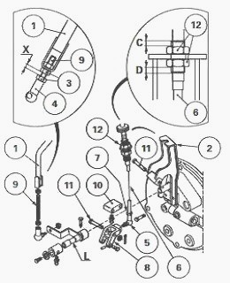
Gear linkage
Fit nuts (3) and ball joint (4) on threaded rod (9) then screw latter
onto link rod (1). Screw ball joint (5) fully onto cable (6). Tighten
nut (7).
Screw and lock the other end of ball joint (5) onto cam (8).
Install bracket (2) and lever "L", then position cam (8) and bellcrank
(10). Fit pins (11) and lock using new splitpins.
Install ball joint (4) on lever "L". Fit the washer and tighten the
locknut.
Adjusting link rod (1) - Turn threaded rod (9) and ball joint (4) so as
to obtain a dimension "X" of 11 ± 1 mm between nuts (3) once latter are
tightened.
Adjusting cable (6) - Adjust the cable stop so as to balance dimensions
"C"and "D". Tighten nuts (12) without changing the setting.
Check for proper engagement of each gear ratio; also check the position
of the gear lever in the opening in the control panel.
This check is to be performed by temporarily moving the boot on the gear
lever.
Engage each gear ratio and select the Hare / Tortoise range. During this
operation, check that the lever does not come within 5 mm of the edge of
the control panel.
If no interference between the lever and the control panel is observed,
the setting is correct. Put back the boot.
If the position of the lever is incorrect, return to the adjustment on
the selector cover side:
- if interference in 1st or 3rd gears, reduce dimension "X".
- if interference in 2nd or 4th gears, increase dimension "X".
- by playing on dimensions "C" and "D", the gear lever can be moved
around in the control-panel opening.
MF 8210, 8220 gearbox reverse shuttle control cables
cab side
Screw clevises level with the end of the threaded part of the cables.
Install the clevises on oscillating lever and position the clips.
Tighten the nuts.
Slide the cable stops into the notches provided on housing. Position and
tighten cover.
Assemble bracket to housing.
Fix housing assy and bracket onto the frame of instrument panel. Ensure
that the cables are fed through the openings in the cab floor. Position
the feed-through
ducts.
Install the floor covering.
Install the surround of the instrument panel and associated items.
Position the reverse/forward lever. Coat screws with Loctite 241 and
install. Fit the boot.
Slide the cables through the clamp located above the MF 8120, 8210 4 WD
transmission-shaft bearing and under the plate connecting the engine to
the gearbox.
Selector cover side
Screw clevises (1) level with the end of the threaded part of cables
(2).
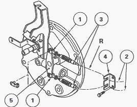
Slide the cable stops (3) (Fig.74) in the notches provided on bracket
(4).
The cable marked with coloured adhesive tape (represented on figure by
the letter "R" must be installed in the upper slot on bracket (4).
Should the mark be
missing, position the cables in the notches such that the position of
the reverse/forward lever in the cab represents the logical driving
position, that is: forward drive -
lever up/reverse drive - lever down.
With the engine stopped, set link (5) to the neutral position then fit
the clevises. Position the clips. Tighten the nuts.
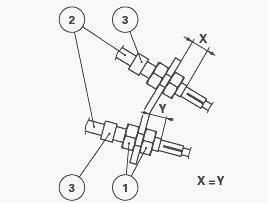
Adjusting cables
Progressively and alternately adjust the tension of the cables using
cable stops (3) so that dimensions "X" and "Y" are identical (Fig.75).
Tighten nuts (1). After
adjustment, the unbent section of reverse/ forward lever must be almost
horizontal.
Consecutively engage forward drive and reverse drive.
Next check that linkage (5) (Fig.74) locks correctly without excessive
tension in the cables.
Version for Massey Ferguson 8220, 8120 tractors with platforms
Two levers installed on the right floor of the footstep are respectively
connected directly with related parts on the cover (Fig.76). They
control operation of the
reverse shuttle, selection of the four basic speeds of the gearbox, and
the Hare/Tortoise range.
The operating principle (mechanical or hydraulic) remains identical to
the system employed on the cab version. In addition, removal, refitting
and disassembly of the
cover are also similar operations.
It is worth noting that the position
and contour of the levers is generally different, and that the system is
simpler and more direct
than on the cab version.
Reverse / Forward lever
- On MF 8220 tractors with a platform, the reverse shuttle is engaged
when lever (1) (Fig.76) is moved either forward (for forward drive) or
backwards (for reverse
drive).
- Moving lever (1) causes rotation of the pin hardmounted to finger (8),
the follower moves selector "S" (Fig.76).
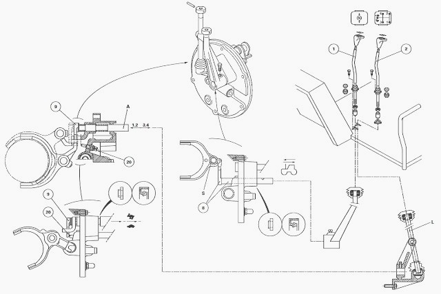
Gear lever
Selecting 1st / 2nd gear
- Gear lever (2) pushes lever "L"and engages finger (9) in the 1st / 2nd
gear fork.
- First gear is obtained by moving lever "L" forward and second gear by
moving it rearward.
Selecting 3rd / 4th gear
- In this configuration, gear lever (2) is in the intermediate position.
Finger (9) integral with shaft "A" is engaged in the 3rd / 4th gear
fork.
- The third ratio is obtained by moving lever "L" forward, and the
fourth ratio by moving it backward.
- Visually identify the location and position of gear lever and
reversing lever. Remove pin and setscrew.
Torque values - Screw (4): 30 - 35 Nm (Loctite 241 or equivalent).
Adjusting the covers on the gear and reversing levers
Adjusting consists in positioning the covers without their interfering
with levers, whilst ensuring maximum protection of the ball joints,
irrespective of which gear is
engaged.
Interference between the cover and the lever may cause
vibration in the stacked parts, and possibly jumping out of gear.
Before adjusting, partially coat the inside of the covers with
anti-seize grease or equivalent.
Set the reverse/forward lever and the gear lever to the neutral
position.
Loosen nuts.
After adjustment, check the condition of the ball joint in the cover,
for all positions of the lever.
Tightening torque - Nuts (1): 44 - 55 Nm.
Adjusting the Hare/Tortoise range
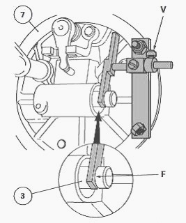
On cover
Install piston (3) fully against the bottom of the chamber (Hare
position).
Position the arm of service tool in the piston groove, and place into
contact with face "F" as shown.
Maintain piston (3) in abutment before tightening knurled screws "V" on
the tool cursor.
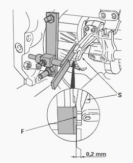
On the gearbox
Install the tool onto the gearbox housing.
Fit the synchromesh ring against third gear "P" (Hare position). The
shoes of the fork must be bearing on the synchromesh ring, on the 3rd
gear side.
Coat the screws of selector "S" with Loctite 221 or equivalent and
adjust so that face "F" is in from the arm of the tool by 0.2 mm
minimum.
Provisionally refit the cover. Use a compressed- air source at 3 bar minimum to blow piston (3) into the Tortoise position.
Locate the opening under the gearbox and check the play of the Hare
/Tortoise fork in the synchromesh ring. Maximum clearance = 1 mm.
After checking the play, remove the cover and definitively tighten the selector screws to 35 Nm without changing the setting. Definitively reinstall the cover.
________________________________________________________________________________
________________________________________________________________________________________
________________________________________________________________________________________
________________________________________________________________________________________
________________________________________________________________________________________
________________________________________________________________________________________
________________________________________________________________________________________
________________________________________________________________________________________
________________________________________________________________________________________
________________________________________________________________________________________
________________________________________________________________________________________
________________________________________________________________________________________
________________________________________________________________________________________
________________________________________________________________________________________
________________________________________________________________________________________
________________________________________________________________________________________
________________________________________________________________________________________
________________________________________________________________________________________
________________________________________________________________________________________
________________________________________________________________________________________
________________________________________________________________________________________

 SPECS
SPECS LOADERS
 MAINTENANCE
 PROBLEMS
 MF 1523
 MF 1531
 MF 135
 MF 1547
 MF 1635
 231
231 231S
231S 235
235 240
240 241
241 255
255 265
265 274
274 285
285 375
375 916X Loader
 921X Loader
 926X Loader
 931X Loader
 936X Loader
 941X Loader
 946X Loader
 951X Loader
 956X Loader
 988 Loader
 1655
1655 GS1705
 1742
1742 2635
2635 4608
4608 1080
1080 1100
1100 2615
2615 3050
3050 3060
3060 4708
4708 5455
5455 5450
5450 5610
5610 5613
5613 DL95 Loader
 DL100 Loader
 DL120 Loader
 DL125 Loader
 DL130 Loader
 DL135 Loader
 DL250 Loader
 DL260 Loader
 L90 Loader
 L100 Loader
 6499
6499 7480
7480 7618
7618 7726
7726 1533
1533 2604H
2604H 2607H
2607H 4455
4455 4610M
4610M 4710
4710 L105E Loader
 L210 Loader
 1014 Loader
 1016 Loader
 1462 Loader
 1525 Loader
 1530 Loader
 232 Loader
 838 Loader
 848 Loader
 5712SL
 6713
6713 6715S
6715S 7475
7475 7615
7615 7716
7716 7724
7724 8240
8240 8650
8650 8732
8732 246 Loader
 1036 Loader
 1038 Loader
 1080 Loader
 856 Loader