
________________________________________________________________________________
Massey Ferguson 8150, 8160 gearbox - Selector cover
Massey Ferguson 8150, 8160 tractors with a mechanical reverse shuttle
are equipped with either a cab or a platform and a selector cover of
similar construction. For the version with the footstep.
The selector cover, installed on the
right-hand side of the housing on the Heavy gearbox, has two separate
levers providing two different functions:
- front lever - for controlling the reverse shuttle,
- rear lever - for selecting the four basic speeds and the two Hare /
Tortoise ratios (Hi - Lo).
Tractors with cab
- Control lever (1) mounted on the left-hand part of the instrument
panel fascia actuates the reverse shuttle via a control cable.
- Control lever (2) located above and to the right of the console
selects the four basic speeds and also acts on the Hare/Tortoise
function, via a rod and cable.
When the MF 8150, 8160 tractor is stopped, cell “C” mounted on a bracket
on the selector cover informs the user that a gear has remained engaged,
and that the
handbrake is on. The warning is issued by a buzzer located under the
instrument panel surround.

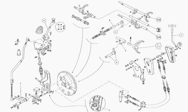
(1) Return ports (2) Grounding lug (3) Screw (4) Temperature probe with
seal. (5) Seal (6) Shouldered ring (7) Selector cover (8) Finger-pin
assembly (reverse
shuttle) (9) Finger-pin assembly (speeds) (10) Grid (11) Screw (12)
Spring (13) Spring cup (14) Spring cup (15) Spring (16) Spring cup (17)
Seal
(18) Shouldered ring (19) Seal(s) (20) Hare / Tortoise switch

Reverse / Forward lever
On Massey Ferguson 8150, 8160 tractors with cabs, lever (1) has the
following positions:
- upwards (forward drive)
- downwards (reverse drive)
Moving lever (1) results in rotation of the pin which is hard-mounted to
finger (8); the follower moves selector “S”.
Gear lever
Selecting 1st / 2nd gear
- Gear lever (2) pushes lever “L” (Fig.70) and engages finger (9) in the
1st / 2nd gear selector fork (Fig.69).
- The first ratio is obtained by moving lever “L” upwards, and the
second ratio by moving it downwards.
Selecting 3rd / 4th gear
- In this configuration, gear lever (2) (Fig.70) is in the intermediate
position; finger (9) integral with shaft “A” is engaged in the 3rd / 4th
gear selector fork (Fig.68).
- The third ratio is obtained by moving lever “L” upwards, and the
fourth ratio by moving it downwards.
Safety interlock - A locking system located on the rear face of the
gearbox, on the end of the selector rails, prohibits accidental gear
shifting.
Hare / Tortoise function

Identification of components
(1) Solenoid valve (2) O’ring (3) Piston (4) Bearing (5) O’rings (6)
Circlip (7) Selector cover
Selecting the Hare / Tortoise range is done with the gear lever in the
neutral position, by pulling lever "L" towards the outside of cover
(Fig. 70). Finger (9) presses
the end of switch (20) (Fig. 68) which informs the electronic system
that the Hare / Tortoise solenoid valve can be switched.
Hare position
Solenoid valve (1) (Fig.71) mounted on selector cover (7) is closed,
which causes a pressure drop in chamber "B".
The constant pressure (17 bar) in chamber "A" is applied to the annular face of piston (3), which moves forward and entrains fork "F1" towards the Hare position under the action of selector "S".
The oil contained in chamber "B"
returns to the sump via the solenoid valve.
Tortoise position
Moving switch (20) (Fig. 68) again causes opening of solenoid valve (1)
(Fig.71). Oil pressurised at 17 bar arrives in chamber "B".
Since the
pressure acting on the
large diameter of the piston is greater than that acting on the annular
face, it forces the piston to retract, driving selector "S" and fork
"F1" towards the Tortoise
position. The oil contained in chamber "A" returns to the 17 bar
circuit.
Removing and refitting the cover
Immobilise the MF 8150, 8160 tractor. Chock the left rear wheel. Set the
handbrake.
Place chocks between the frame and the front axle.
Remove the right rear wheel or set to wide tread. Install an axle stand
if necessary.
Pivot the footstep assembly and battery chest or remove any neighbouring
parts likely to impede removal of the selector cover (depending on
version).
Drain the gearbox.
Disconnect the electrical harnesses on the cover.
Unscrew the tube and hose unions.
Tractors with cabs
Gear control. Disconnect the harness from cell "C" (Fig.70). Remove ball
joint (4). Remove screw (3).
Remove pins (11). Disconnect ball joint (5).
Note the adjustment of cable (6).
Slightly loosen upper nut (12) and
separate the cable from bracket (2). Reverse shuttle control.
Remove clips (1). Note the adjustment of cables (2). Loosen nuts (3).
Separate the cables from bracket (4).
On MF 8160, 8150 tractors fitted with a creeper unit, disconnect control
cable (1).
Remove screws (3), taking care to identify the position of grounding lug
(2).
If installed, remove bracket (2) supporting the creeper control cable.
Release and remove the selector cover.
Clean the mating faces on the gearbox and cover.
Install the following parts:
On the cover: the Hare / Tortoise piston in the "Hare" position
On the gearbox: the Hare / Tortoise fork in the "Hare" position, the 1st
/ 2nd gear and 3rd / 4th-gear selector forks and the reverse shuttle
fork in the neutral position.
Coat the mating face of the gearbox housing with sealing compound
(Masterjoint 510 Loctite or equivalent).
Turn the gear and reversing control linkage on the cover to engage them
in their respective selectors during positioning of the cover on the
gearbox.
Install the bracket for the creeper control cable (if installed).
Position lug (2). Install screw (3) and torque to 34 - 51 Nm.
Depending on the option, reconnect and adjust the creeper gear control.
Reassemble the gear control.
Reassemble the reverse shuttle control.
Use a grease gun to grease the joints of the gear control on the
selector cover.
Install any items previously removed around the cover.
Replace the wheel and torque the screws or nuts depending on the
version.
Service the oil in the sumps and check the level in the sight glass
located on the left-hand of the centre housing.
Remove the chocks between the frame and front axle. Release the handbrake. With the engine running, check passage of all gears and the reverse shuttle. Also check the Hare/Tortoise position.
If necessary, and with
the engine stopped,
adjust the controls.
Check that the buzzer of the safety cell vibrates correctly (contact
set, handbrake on and gear engaged).
Carry out a road test.
Replacing the Hare/Tortoise piston seals
Remove the cover.
Remove circlip (6). Extract piston (3) with bearing (4) and scrap
O’rings (2) and (5).
Clean and check the parts; replace any that are faulty.
Without installing the O’rings on the piston, check that the latter
slides freely in the bore in the cover.
After inspection, lubricate and fit new O’rings.
Install the selector cover. Replacing piston (3), bearing (4) or circlip
(6) implies checking or repeating the setting of selector "S" on the
Hare/Tortoise range.
Disassembling and reassembling the selector mechanisms
Remove the cover and tighten in a soft-jaw vice.
Tractors Massey Ferguson 8160, 8150 with cabs
Remove screws (1) and (4). Remove selector (3), link rod (5) and bracket
(2).
Remove the pin integral with finger (8).
Remove screw (11). Remove the gear control assembly.
Remove cup washers (14) and (16) and spring (15).
Separate the assembly comprising pin and finger (9) from grid (10).
Remove spring cup (13) and spring (12).
If necessary, unscrew and remove Hare/Tortoise switch (20), the threaded
fittings on return ports (1), and temperature probe (4). Recover seal(s)
(19) from the
Hare / Tortoise switch.
Extract seals (5) and (17).
If considered necessary to replace guide rings (6) and (18), lightly
coat the edges of the replacement rings with Loctite 638 or equivalent
and fit them tight so that
they come into contact with the shoulders on the cover.
If removed, reinstall Hare / Tortoise switch (20) with the same number
of seals as removed. Apply a light coat of Loctite 542 to the threads of
the return port and the
temperature probe unions, then refit the unions.
Lightly coat the outside diameter of seals (5) (17) with Loctite 542,
then fit the seals tight onto cover using a suitable fixture.
From the inside of the cover, refit the pin-finger assembly (8) without
damaging the lip of seal (5).
Install reversing linkage (5). Coat the threads of screw (4) with Loctite 241 or equivalent and install the screw. Torque to 30 - 35 Nm. Reassemble spring (12) and spring cup (13) on shaft (9).
Assemble the
shaft with grid (10). Reassemble cup washers (14) (16), with spring (15)
in between.
Install the pin-finger assembly (9) without damaging the lip of seal
(17). Coat threads of screw (11) with Loctite 270 or equivalent. Install
the screw and torque to 25 -
35 Nm.
Positioning bracket
Install bracket (2), observing a clearance of 29 mm between the bracket
and the 22-mm diameter of shaft “A” (Fig. 72). Lightly coat screw (1)
with Loctite 270 or
equivalent, fit the screw and torque to 25 - 35 Nm.

Positioning bracket
This clearance MUST be observed to ensure correct operation of the cell.
Reassemble linkage (3). Coat threads of screw (4) with Loctite 241 or
equivalent, fit the screw and torque to 30 -35 Nm.
Check that the selector mechanisms move freely. Remove the cover from the vice and refit to the Gearbox.
________________________________________________________________________________
________________________________________________________________________________________
 SPECS
SPECS LOADERS
 MAINTENANCE
 PROBLEMS
________________________________________________________________________________________
 MF 1523
 MF 1531
 MF 135
 MF 1547
 MF 1635
________________________________________________________________________________________
________________________________________________________________________________________
 231
231 231S
231S 235
235 240
240 241
241________________________________________________________________________________________
 255
255 265
265 274
274 285
285 375
375________________________________________________________________________________________
________________________________________________________________________________________
 916X Loader
 921X Loader
 926X Loader
 931X Loader
 936X Loader
________________________________________________________________________________________
 941X Loader
 946X Loader
 951X Loader
 956X Loader
 988 Loader
________________________________________________________________________________________
 1655
1655 GS1705
 1742
1742 2635
2635 4608
4608________________________________________________________________________________________
 1080
1080 1100
1100 2615
2615 3050
3050 3060
3060________________________________________________________________________________________
 4708
4708 5455
5455 5450
5450 5610
5610 5613
5613________________________________________________________________________________________
 DL95 Loader
 DL100 Loader
 DL120 Loader
 DL125 Loader
 DL130 Loader
________________________________________________________________________________________
 DL135 Loader
 DL250 Loader
 DL260 Loader
 L90 Loader
 L100 Loader
________________________________________________________________________________________
 6499
6499 7480
7480 7618
7618 7726
7726 1533
1533________________________________________________________________________________________
 2604H
2604H 2607H
2607H 4455
4455 4610M
4610M 4710
4710________________________________________________________________________________________
 L105E Loader
 L210 Loader
 1014 Loader
 1016 Loader
 1462 Loader
________________________________________________________________________________________
 1525 Loader
 1530 Loader
 232 Loader
 838 Loader
 848 Loader
________________________________________________________________________________________
 5712SL
 6713
6713 6715S
6715S 7475
7475 7615
7615________________________________________________________________________________________
 7716
7716 7724
7724 8240
8240 8650
8650 8732
8732________________________________________________________________________________________
 246 Loader
 1036 Loader
 1038 Loader
 1080 Loader
 856 Loader