
________________________________________________________________________________
Massey Ferguson 8260, 8270 heavy duty gearbox - Creeper unit
Massey Ferguson 8260, 8270 tractor fitted with heavy duty gearbox may also be fitted, depending on the options, with a creeper gear reducer unit.
This reducer unit (24) consists of a simple epicyclical gear train comprising a planetary carrier and a crown and placed at the rear of the heavy duty gearbox.
The link fitted to the front right-hand side of the intermediate housing
operates the control fork of the reducer via a cable linked to a lever
located in the tractor cab.

The coupler can only be activated when the MF 8260, 8270 tractor is
halted pinion (9). Moving the control lever towards the "Snail" position
moves the coupler to the rear and connects it to the planetary carrier
(20) via the intermediary of the coupler ring (22).

The rotational speed of the drive pinion is one quarter of that of the
output shaft of the gearbox. In normal gears, when the coupler is moved
forward the output shaft of the gearbox is linked to the drive pinion,
thus ensuring direct transmission.
Lubrication - The lubricating of the epicyclical reducer is carried out
by splashing caused by its moving components.

(1) Nut (2) Ring (9) Drive pinion (11) Snap ring (12) Friction washers
(13) Pins (14) Friction plates (15) Planetary gears (16) Crown ring (17)
Spacers (18) Needle bearings (19) Intermediate housing (20) Planetary
carrier (21) Snap ring (22) Coupler ring (23) Bolt (24) Planetary
carrier assembly (reducer) (26) Nut (27) Fork (28) Selector rail (29)
Link (35) Locking stud (36) Spring (37) Plug (38) Pin (39) Index (40)
O’ring (41) pin (42) Link (43) Bolt (44) Housing (45) Shim(s) (46)
Splined bearing (47) Output shaft (48) Bolt

Removing and remounting the Unit
Uncouple the Massey Ferguson 8270, 8260 tractor between the gearbox and
the intermediate housing.
Removing the unit
Take off ring (2) and bolt (23) fitted respectively to the output shaft
(47) and the housing (44).
Remove the components making up the reducer assembly (24) on the
gearbox.
On heavy duty gearboxes fitted with a creeper gearbox, bearing (46) is
different from that fitted to the standard version.
Machined splines on its edge connect it to the crown ring (16).
Refitting
Carry out a visual inspection of all components.
Lightly smear the faces of the reducer with miscible grease and fit the
friction washers (12) with their tabs located in the appropriate
grooves.
Replace the reducer assembly on the output shaft
- a machined area on the external diameter of the crown ring ensures
that the rear cup of the layshaft of the gearbox stands clear.
- the cutaway part of the housing (44) faces downwards.
Check the correct positioning of the components and tighten bolts (23)
smeared with Loctite 241 to a torque of 10 - 14 Nm. Manually check for
the rotation of the
gearbox output shaft.
Couple the MF 8270, 8260 tractor between the gearbox and the
intermediate housing.
Disassembling, reassembling and adjusting the selector

Uncouple the MF 8260, 8270 tractor between the gearbox and the
intermediate housing.
Disconnect the control cable fitted to the link (42).
Disassembly
To take off the coupler (29), it is necessary to remove drive pinion (1)
from the hydraulic pumps. Remove plug (37), recover spring (36) and
locking pin (35).
Remove the selector rail assembly (28) and nut (26). If necessary, break
the seal, unscrew and take off nut (26). Remove rear ring (2), take off
the lug washer (3)
and spring (12). Immobilize the pinion and remove bolts (4).
Extract pinion (1) from bearing (11) and simultaneously take out the
assembly (pinion, fork and coupler) through the front of the housing.
Remove the control link (42) located on the right hand side of the
intermediate housing. Drive out pin (38) and remove index (39). Recover
the shim(s) (45) and
remove pin (41) complete with o’ring (40).
Refitting
Lubricate a new o’ring (40) and place it on pin (41).
Place the pin in the chamfered port located on the exterior of the
intermediate housing (19).
To limit the axial clearance, it is recommended to shim to a tolerance
of 0.1 to 0.6 mm.
Shimming
On the axle, place the approximate thickness of shims (45). Fit index
(39) and partially place the pin (38). Refit the link (42) and bolt
(43).
Manually evaluate the clearance.
The adjustment principle consists of obtaining the minimum clearance
between the various components.
Action
If the clearance is outside the maximum allowed tolerance, determine a
new thickness of shims required. After shimming, check for correct
orientation of the index
and the link.
Definitively insert pin (38), fit and tighten Allen screw (43). Rearrange the assembly (pinion, coupler, and fork) in the intermediate housing. Immobilize the pinion again.
Fit and tighten the bolts (4) lightly smeared with Loctite 241 to a torque of 72 - 96 Nm. On bearing (11), replace in their correct positions the spring, lug washer and ring. Refit the selector rail and nut assembly.
Adjust the fork.
Couple the tractor between the gearbox and the intermediate housing.
Reconnect the control cable and where necessary carry out its
adjustment.

Adjustment
- Fit locking stud (35), spring (36) and plug (37). Partially tighten
the plug.
- Place coupler (29) in the F1 “creeper gear” position, the rear face
thrusting against the M60 nut (1).
- In F2, maintain the fork thrust against the coupler.
- In F3, turn the selector rail (28) in nut (26) so as to place in
contact the oblique side of groove G2 with locking pin (35) while
simultaneously holding nut (26) against
spotface B of the intermediate housing (19).
- Using a depth gauge, measure distance X1 between the front face of the
selector rail and face A of the housing.
- In F2, maintain the fork thrust against the coupler.
- In F4, turn the selector rail in the nut so as to place the other
oblique face of groove G2 in contact with the locking stud while
maintaining nut (26) as previously.
- Measure distance X2 in the same way as X1.
- Determine the X adjustment position using the following formula: X =
(X1 + X2) 2
- Provisionally position the selector rail (28) at dimension X.
- Place the coupler (29) in the "direct drive" position; manually check
the locking of the control and the clearance between the fork and the
coupler. Take care also
that the coupler is not in contact with the hydraulic pumps drive
pinion.
- If this check is satisfactory, take out plug (37), the spring and the
locking pin.
- Degrease the threads of the selector rail and those in nut (26).
- Lightly smear the nut threads with Loctite, tighten the nut and
definitively position the selector rail, in accordance with the
previously calculated dimension X.
- Lock the nut by bending its collar into the machined slot on the
selector rail.
- Replace the locking assembly. Tighten plug (37) to 50 - 70 Nm.
Disassembling and reassembling the epicyclical reducer

Disassembly
Remove the unit. Take off the circlip (11). Remove the friction washers
(12).
Drive out the pins (13) Remove the planetary gears (15) from the
planetary carrier (20) taking care not to lose the needles (18), the
spacers (17) and friction plates
(14).
The coupler ring (22) is inserted into the planetary carrier using a
press. The snap ring (21) ensures additional locking of the various
components.
Reassembly
Inspect and clean all components. Replace any defective parts.
Fit each planetary gear with two rows of needles smeared with miscible
grease and separated by a spacer.
Replace the planetary gears and position the friction plates (14). Refit pins (13), correctly orienting them to correspond with snap ring (11).
Place the snap ring. Manually check the axial clearance and rotation of each planetary gear.
Lightly smear the faces of the reducer with miscible
grease and fit the friction washers (12), with their lugs lodged in the
appropriate grooves. Refit
the unit.
Control adjustment

On lever "A"
Place control lever “A” in the “Snail” position. Screw clevis (1) flush
with the threaded part of the cable (6). Mount clevis (1) on lever "A"
with clip (7). Tighten nut (2).
Tighten nut (3) on the knurled sheath end (5). Fit the knurled sheath
end and Grower washer onto the support piece. Tighten nut (4) while
checking that the cable is
not pinched.
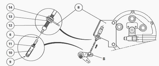
On link "B"
Place link "B" in the "creeper gearbox" position (coupler (29) engaging
the splines of the planetary gear carrier (20) (Fig. 2) and with the
fork locked).
Screw clevis (9) flush with the threaded adjuster of the cable (6). Fit the clevis (9) on to link "B" using clip (10). Tighten nut (11).
Adjust the stop (12) using nut (13) on support (8) while checking that link "B" is still correctly locked.
Tighten nut (14) and check that the cable is not pinched. Check the operation and locking of the control in the "direct drive" position.
________________________________________________________________________________
________________________________________________________________________________________
 SPECS
SPECS LOADERS
 MAINTENANCE
 PROBLEMS
________________________________________________________________________________________
 MF 1523
 MF 1531
 MF 135
 MF 1547
 MF 1635
________________________________________________________________________________________
________________________________________________________________________________________
 231
231 231S
231S 235
235 240
240 241
241________________________________________________________________________________________
 255
255 265
265 274
274 285
285 375
375________________________________________________________________________________________
________________________________________________________________________________________
 916X Loader
 921X Loader
 926X Loader
 931X Loader
 936X Loader
________________________________________________________________________________________
 941X Loader
 946X Loader
 951X Loader
 956X Loader
 988 Loader
________________________________________________________________________________________
 1655
1655 GS1705
 1742
1742 2635
2635 4608
4608________________________________________________________________________________________
 1080
1080 1100
1100 2615
2615 3050
3050 3060
3060________________________________________________________________________________________
 4708
4708 5455
5455 5450
5450 5610
5610 5613
5613________________________________________________________________________________________
 DL95 Loader
 DL100 Loader
 DL120 Loader
 DL125 Loader
 DL130 Loader
________________________________________________________________________________________
 DL135 Loader
 DL250 Loader
 DL260 Loader
 L90 Loader
 L100 Loader
________________________________________________________________________________________
 6499
6499 7480
7480 7618
7618 7726
7726 1533
1533________________________________________________________________________________________
 2604H
2604H 2607H
2607H 4455
4455 4610M
4610M 4710
4710________________________________________________________________________________________
 L105E Loader
 L210 Loader
 1014 Loader
 1016 Loader
 1462 Loader
________________________________________________________________________________________
 1525 Loader
 1530 Loader
 232 Loader
 838 Loader
 848 Loader
________________________________________________________________________________________
 5712SL
 6713
6713 6715S
6715S 7475
7475 7615
7615________________________________________________________________________________________
 7716
7716 7724
7724 8240
8240 8650
8650 8732
8732________________________________________________________________________________________
 246 Loader
 1036 Loader
 1038 Loader
 1080 Loader
 856 Loader